My Nixie Clock Project
by Peter H. Wendt
Rel. 0.9.5_en, Last Update: Wednesday, 2009-11-18
Most common question: "Your what Clock Project ?"
Before Light-Emitting Diodes (LEDs) and Liquid Crystal Displays (LCDs) the electronic industry
used cold-cathode tubes for displaying numbers, symbols and even characters. Even though they
are called "tubes" they differ from "radio tubes" by having no heater wire to heat the cathode - and
therefore run much colder. They do have a glass envelope but unlike to (most) tubes they are not
empty: they are filled with a gas compound, mainly neon gas. If you apply a voltage between the
anode (+ pole) and one of the cathodes (- poles) the character-shaped cathode is covered with a
pink to orange discharge glow.
"NIXIE" was a trademark from Burroughs Corp. for their numeric display tubes. It is rumoured
that they invented this kind of tube - or at least they got patents for it. There were many different
types of these tubes: viewed from the side, viewed from the top, small ones, big ones, giant sized,
types where a neon glows through a character-shaped mask and arrays of multiple nixies with
multiplexed wires. Even early "multi-segment" types were available, capable to display letters like
the later LED 7-segment arrays.
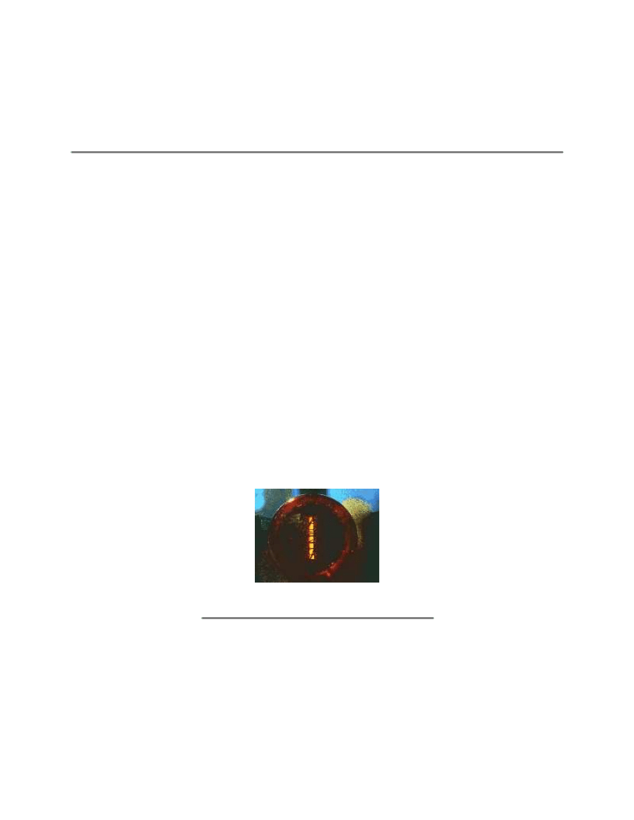
The animation below shows the button-like, top-viewed ZM1020.
It is a Nixie with 15 mm (0.6") character height.
You got the idea, right ?
Now for some technical theory.
Basically these Nixie tubes are very simple devices. The following schematic will explain, how
they work.
My Nixie Clock Project
http://www.mcamafia.de/nixie/ncp_en/ncp.htm
1 von 17
28.01.2013 12:49
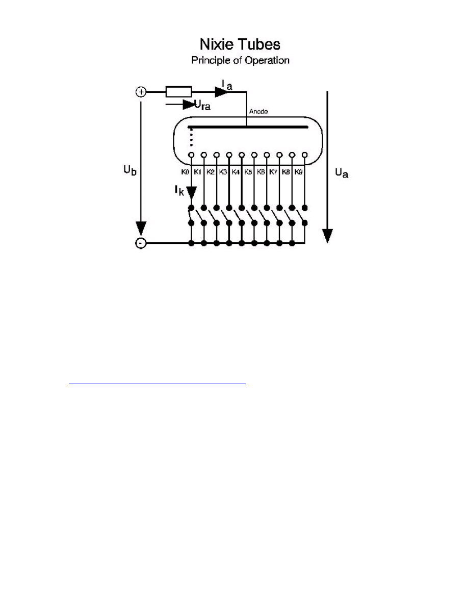
If you apply a voltage U
b
the voltage drops across the current-limiting resistor when one of the
cathodes K0 - K9 is tied to GND. The corresponding number-shaped cathode is then covered with
a pink to orange glow. The values for the minimum U
b
, the anode voltage U
a
and the cathode
current I
k
needs to be taken from the nixie tube datasheet, but you can estimate 140 VDC for U
a
and 2 mA for I
k
as good starting values for most nixies.
If your U
b
is about 220 VDC a 47K resistor / 0.5 Watts will do for some testings.
The
datasheet for the very common ZM1080 / 1082
says that U
b
should be at least 170 VDC and
the I
k
should settle at around 2 mA. U
a
will then establish at about 140 VDC "maintaining"
voltage (noted as V
m
in the datasheet). The difference between U
b
and U
a
is the U
ra
that drops
across the limiting resistor.
For a simplification we assume that the anode current I
a
is equal to the cathode current I
k
- you
will have to tie only one cathode pin to GND at one time anyway. Nixies that use a "primer
current" for faster ignition response have uneven anode and cathode currents. But we may leave
that aside here.
Advantage: If you rig a multimeter in Milli-Amperes range into the (common) anode line during
the testing you can track the current through the Nixie tube while connecting the cathode pins or
leads to GND - without needing to meddle around with the meter wires. The unused cathode pins
are left open (the term "floating" is used often). You will be able to measure voltages up to U
a
on
the pins not connected.
Further advantage: if you have several Nixies in a circuit, these have all one common U
b
wire. If
you install a mA-Meter in that line you get the total current drawn for all nixies. And can assume
that the individual current is total current divided by the number of tubes you are using. This is not
My Nixie Clock Project
http://www.mcamafia.de/nixie/ncp_en/ncp.htm
2 von 17
28.01.2013 12:49
absolutely true - but we won't win the Noble Prize with a very precise research on that anyway.
Some quick maths to calculate the values for the limiting resistor
U
ra
= U
b
- U
a
-> 220 V - 140 V =
80 VDC
R
a
= U
ra
/ I
a
-> 80 VDC / 0.002 A =
40.000 Ohms
P
ra
= U
ra
* I
a
-> 80 VDC * 0.002 A =
0.16 Watts
Since there is no 40 KOhms resistor in the range of ordinary E24 5% standard resistors it will
surely do if you pick a 43 KOhms type 0.25 Watts here, not to exceed the 2 mA cathode current.
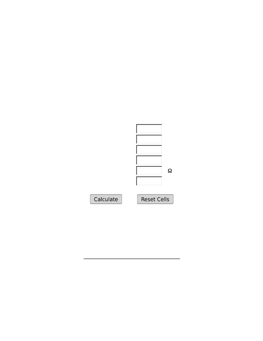
Calculation
for the Nixie Anode-Resistor
Supply Voltage U
b
220
V
Anode Voltage U
a
140
V
Cathode Current I
k
2.0
mA
U
ra
:
V
R
a
:
K
P
ra
:
Watt
If you just press [Calculate] the values for the given U
b
, estimated U
a
and the given cathode
current I
k
are used and the output is the current across the anode resistor U
ra
, the resistor value in
Kilo-Ohm and the thermal loss P
ra
of the resistor in Watt.
For your own calculation just overwrite the values in the upper 3 lines with what you need and
then click on [Calculate] again.
220 VDC is quite a bit. How to get them safely ?
Well ... the professional approach is to have either a special transformer for the required voltages
or at least an isolated 1:1 ratio separation transformer. If you live in the "low voltage" areas of the
world where 110 VAC is the usual AC mains voltage you may survive a shock from the life wire.
If you life in the "high voltage" areas like here in Germany the 230 VAC line voltage will surely
kill you if you accidentially happen to be good grounded. A 1:1 transformer isolates the input
voltage from the output voltage so you are not directly connected to AC mains. The 230 VAC that
My Nixie Clock Project
http://www.mcamafia.de/nixie/ncp_en/ncp.htm
3 von 17
28.01.2013 12:49
goes in comes out as 230 VAC - but you have no connection to Earth (GND) when touching any
wire. You are -nontheless- toasted if you touch both wires at one time.
The professionals phrase is "galvanically separated" - it is good to know that.
Separation transformers are usually big, heavy and expensive. Not as expensive as your life of
course, but enough to blow a budget. In our case however we don't need Kilowatt capabilities. A
few Watts will do - so we can build our own separation transformer by simply using two small
transformers "Back to Back".
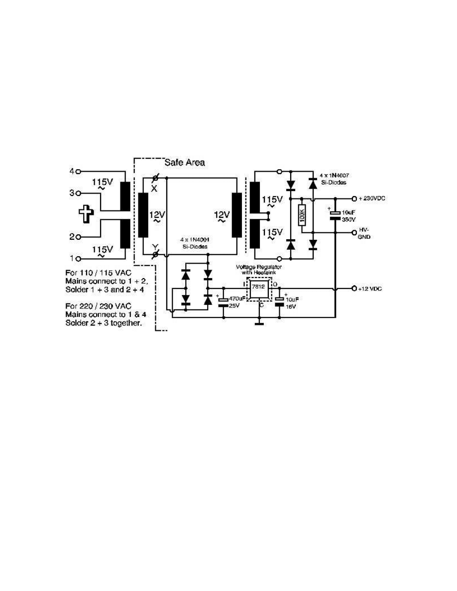
The graphic below will show this simple solution.
The transformers can be simple, relatively cheap print-type transformers with greater 4 Watts
output power. The ones I used on my prototype clock are rated 4 VA (Volt-Amperes) with a single
230 V primary input and a single 12 V / 300 mA output. If you cannot get those - take two with
e.g. 15 VAC or two with 8 V AC. The "intermediate voltage" between the two is of lesser
importance, it is used for the logic board only. But at least the "one on the right side" must have a
230 V coil.
If you have two different transformers: the bigger (stronger) one must be the one connected to
AC-mains. You cannot run a 10 Watt transformer from a 5 Watt type back to back for example.
The 10 Watt has a lower resistance for the secondary coil - and the 5 Watt secondary coil is then
overloaded. At least when you add load to it. It may work for some time however, but not reliably.
The 4 diodes 1N4001 for the low voltage circuit can be replaced by a block rectifier like the
B40-C1000 for instance; the 4 diodes 1N4007 for the high voltage part can be substituted by e.g. a
B1000-C125 rectifier bridge. This rectifier(s) must be capable to run continously with 350 V at
least, so the minimum were a 1N4004 (rated 400V).
Other than that there are no secrets in that circuit. The 100 KOhms parallel to the 10 µF/ 350 V
capacitor in the HV part helps - for safety - discharging the capacitor when no load is placed
My Nixie Clock Project
http://www.mcamafia.de/nixie/ncp_en/ncp.htm
4 von 17
28.01.2013 12:49
across the output. That's all. For your own pleasure you may add a 1 KOhms resistor at the +12V
output and a red LED ... to remind you to the fact that the power supply is switched on.
With my two 4-Watt Transformers I get 15 V AC in idle between the
transformers, 210 V AC idle voltage at the HV end. Also in idle the
DC-voltages across the rectifiers are 18.5 V resp. 290 V DC. The high
voltage however drops down to about 200 VDC when loaded with 4 x
ZM1080 or 4 x ZM1020 Nixies and a total of 4.8 mA current drawn.
A power supply built like that will suffice to play around with various
types of Nixie tubes and get some insights on how they work.
Important: Security - and some useful hints
If you use a power supply like that above you will need a medium-blow 0.315 Amps fuse in one of
the AC main wires for protection when -in the worst case- the transformer goes south. You should
also install the whole power supply unit in a plastic case so that it is factically impossible to touch
any AC-line wire. That unit shown above is a prototype not intended to be really used that way.
If you can get one of these "wall wart" transformers that have about 500 mA at 12V AC you are
fine off. In this case you only need one transformer in the clock itself and a power socket where
the AC-Adapter plugs to. For the above schematic the left-hand transformer is your external wall
adapter and the AC-input socket connects to the points marked with "X" and "Y" then.
Some DC-Adapters can be reworked: if you can open the case of it without destroying it - just
unsolder the diodes and the filter capacitor that can be found in most of them and connect the
output wires directly to the secondary side of the transformer. Then you only need the part of the
power supply further above that is right from the left (input) transformer. The 12 V AC (or 8 or 9
or whatever) comes from the wall-wart and your second transformer must be choosen accordingly.
And -if you go lower- the 7812 must be replaced by e.g. a 7508 (8 V output) or 7805 (5 V output).
The circuit itself doesn't care much when running with anything between +5 and +15 V DC.
If you opt for that solution you can make your clock case from "more dangerous material", like
steel, copper, sheetmetal, carbon-fibre or anything else conductive. You don't have the AC line fed
into the unit and the worst thing that can happen is, that you shorten your electronics elsewhere
and it simply doesn't work -or- damages the transformer(s).
Okay - but why building a clock from these Nixies ?
Good question. Today you can pick a lot cheapo LCD clocks from supermarkets for a few bucks.
But - how do they look ? Simply boring.
Go back to the Nixie animation further above. Look at it for a while and I'm sure you can spot the
difference.
I built digital counters and clocks with LED 7-segment displays and 74xx TTL-chips already in
the 70's. The commercial clocks used ready-made circuits, offered alarm and such, but they looked
cheesy cheap - didn't match my taste - and those who did were horribly expensive. So I made my
own desktop clock.
Same reason for the Nixie Clock: a custom-made case, antique looking glass tubes somewhere in
My Nixie Clock Project
http://www.mcamafia.de/nixie/ncp_en/ncp.htm
5 von 17
28.01.2013 12:49
it or placed on top - a wide variety of possibly creative, unusual designs. You can make it from all
material you'd always wanted to build a clock from. Wood, steel, acrylic plastic. Transparent,
translucent or granite-solid.
However: the Nixie Clock described here is Just A Clock. Not a stop watch, timer, alarm clock or
anything like that. You may add some "Bells and Whistles", but due to the nature of the circuitry it
might be a bit complicated. More on that later.
Getting started with it: the proper timing
Heart of any clock is a source for a timing signal. Cheap AC-powered alarm clocks use the 50 or
60 Hz AC line to generate a more or less accurate clock-signal from it. Usually that would do -
given that the accuracy over the whole year on the AC-line is within a 1 % range. Nontheless I'd
decided not to use that. First reason was to be independent from the AC frequency. Secondly a
crystal oscillator offers even better accuracy than line-AC and third I had a circuit at hand anyway
I used for a couple of applications in the past. Main advantage: it operates with a generic 32.768
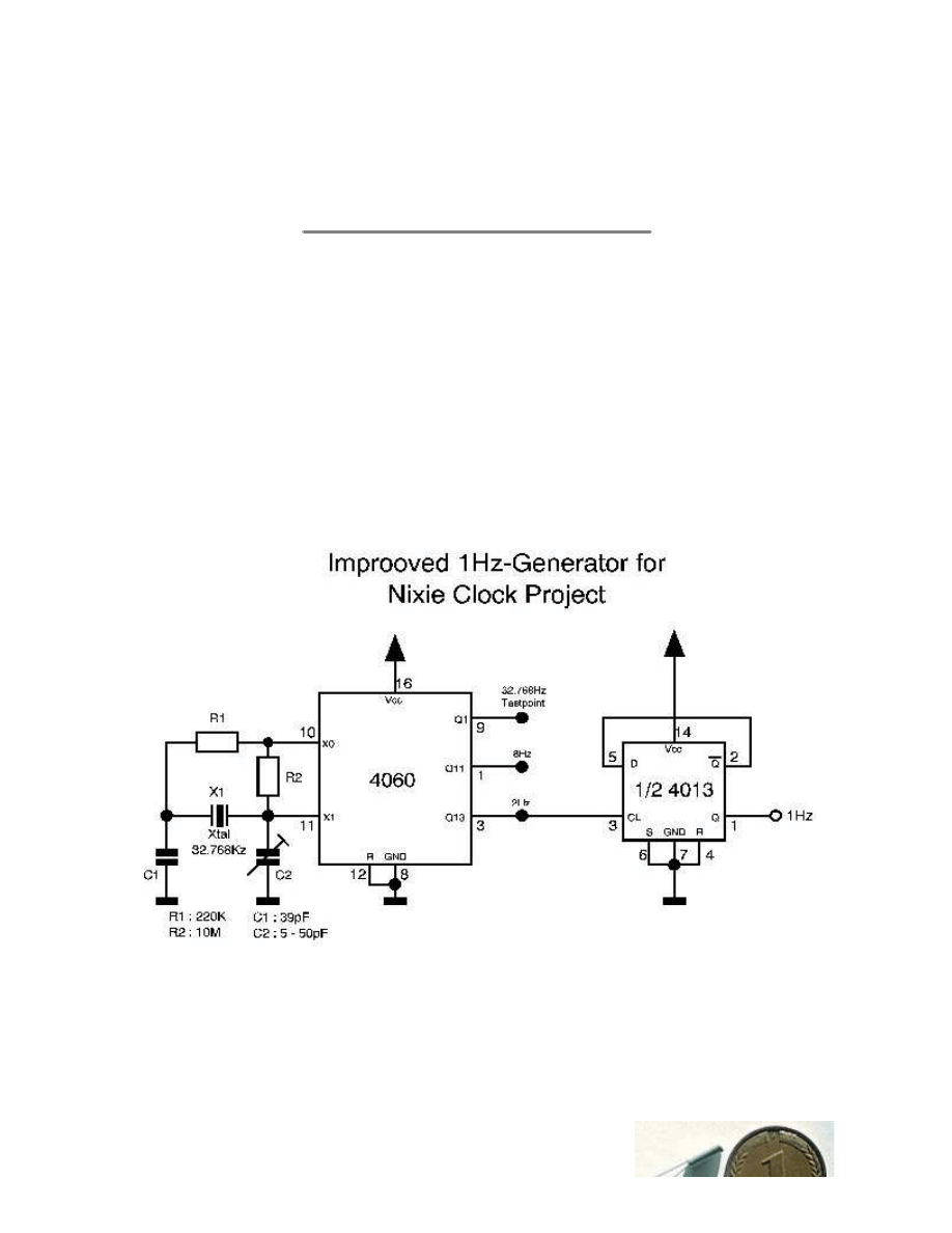
KHz mini crystal widely available - and comes out with a 1 Hz timing pulse. The schematic below
shows the circuit.
There are two resistors: R1 acting as current-limiting resistor and R2 bias resistor. This latter one
is a) dependent to the circuit voltage applied to the 4060 divider chip and b) dependent to the
current flow through the crystal and its capacity. I made good results with either omitting this one
or using a 10 Mega-Ohms to start with. Your individual mileage may vary.
The crystal I used is a miniature clock crystal X1 in a round case
with 19 pF internal capacity. The "tie-up" capacitor C1 is a low-loss
My Nixie Clock Project
http://www.mcamafia.de/nixie/ncp_en/ncp.htm
6 von 17
28.01.2013 12:49

ceramic type, the trimmer capacitor C2 is a standard plastic type.
With a frequency counter connected to the 4060's pin 9 you can
measure the buffered crystal frequency and adjust it to read exactly
32.768 Hz.
The 4013 RS Flipflop is used to divide the 2 Hz from the 4060 down to the 1 Hz base clock. The
second half of the 4013 might be used to divide the 8 Hz signal at pin 1 down to 4 Hz for a "fast
forward" set mode - not shown here however. If you are not using the second half of the 4013: tie
the pins 8, 10 and 11 to GND and connect 9 and 12. Pin 13 stays open. If you decide to use the
4013 pin 11 is your input, 13 the output.
It is highly recommended to keep the wires of the components (caps and resistors) short trimmed
and the leads between the components as short as possible. If the oscillator fails to start up or dies
after several seconds: make the bias resistor larger. It may go up to 10 MOhm with these miniature
crystals - or even left away. The bigger HC-style crystals with higher internal capacity may require
100 KOhm - 1 MOhm bias resistors. If you don't want a trimmer capacitor you may use a ceramic
capacitor of the same value as C1 as well. Doesn't hurt the overall accuracy that much.
In the meantime - after I edited this page for the last time - I had built numerous oscillators with
the 4060 and got a lot responses from other folks. Alternative concepts for the trimmer position,
values of R1 and R2 and the C1 and C2 have been discussed.
Usually you have a datasheet for the mini xtal X1 to start with. This datasheet shows the internal
capacity - which *use to be* about 16 - 19pF.
The value for the tie-up cap C1 should be 2x the xtal capacity. 39pF fits quite nicely here.
The value for C1 should be [xtal capacity < C2 < 3x xtal capacity], where 5 - 50pF covers the
entire range.
Determining the values for R1 and R2 is more tricky.
While R2 could be ommitted in the best case for very dense packing of components R1 is essential
for the clean function here. If it is too high the xtal fails to start - if it is too low the xtal enters
"overtone mode" and the oscillator output frequency is either totally erratic or way higher than
supposed.
For R1 220KOhm has prooved to be a good value, R2 should be 10M. If you have xtals larger than
these micro-types your R1 needs to be reduced - down to 2K2 for a HC32 xtal and R2 might be
reduced to 4M7 for stable operation.
The 4060 allowes to run at up to 4MHz @ 15V supply. If you have too much room and wouldn't
care about two more 4017 dividers: pick a 3.2768 MHz xtal, leave R1 away or reduce it to 2K2,
R2 to 10M, C1 to 22pF and install a 2 - 22pF trimmer. You get 200Hz at the Q13 - divided by 2 in
the 4013 for 100Hz. Add two more 4017s and you are again at 1Hz with -probably- higher
stability due to the higher reference frequency. However: you should not test the 4060 frequency at
pin 9. The probe capacity will alter the result. You should test at O4 (pin 7) and your counter
should read 204.800 Hz. The trimmer allows a change of about +/- 25 Hz. If you don't have one
adjust C2 to the center, where about the half of the static "leafes" are visible. That will do to for
most cases.
Step by Step: the dividers (Seconds, Minutes and Hours)
My Nixie Clock Project
http://www.mcamafia.de/nixie/ncp_en/ncp.htm
7 von 17
28.01.2013 12:49
At that point we've got to hold for a moment and think about a basic design question:
"Do we want a seconds display or only minutes and hours ?"
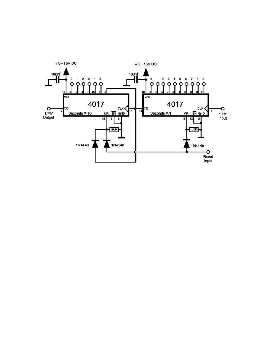
In either case we need two 60-stage dividers. Building a clock without a seconds display saves
room and driver transistors. Let's have a look at this part of the circuit.
The CMOS chip 4017 is a "5-stage Josephson decade counter" with built-in code converter. Each
low-to-high transitition (= "positive edge") on the clock input 14 advances the counter one
position up from Q0 to Q9, which go to high level then. A logical "1" signal on the reset input 15
sets it back to Q0.
To count the seconds properly we have to pull the first counter reset to GND with a 100K resistor,
which causes the counter to count from 0 to 9 with every clock signal. At 9 it jumps back to 0 with
the next clock pulse and the "Carry Out" signal at pin 12 changes from "0" to "1", which counts
the second counter one position up. The second counter has the Q6 output wired to the reset pin.
After the 59th clock pulse it jumps back to "00". Any of the "Carry Out" signals changes back
from "1" to "0" after receiving the positive edge of the 6th clock pulse.
The capacitors on each pin 16 are local buffer caps only. They are there to reduce the effect of
local voltage sags. This is mainly an issue when the circuit is built on experimental board or with
no board at all. Given you have a stable, clean supply voltage it will surely suffice to leave them
away or add one or two of them on the chips farthest away from the point where the supply
voltage is fed into the circuit.
The "100nF" rating seems to be a tad uncommon to some people. It has been brought to my
attention that it may lead to some confusion and I had been asked if I meant "microfarad" instead
(but didn't have the proper sign). No - it is Nanofarad. Or - alternatively - I could use "0.1 µF" here
to clarify what I meant.
The Seconds Divider is followed by the Minutes divider. Looks in most of it like the Seconds
My Nixie Clock Project
http://www.mcamafia.de/nixie/ncp_en/ncp.htm
8 von 17
28.01.2013 12:49
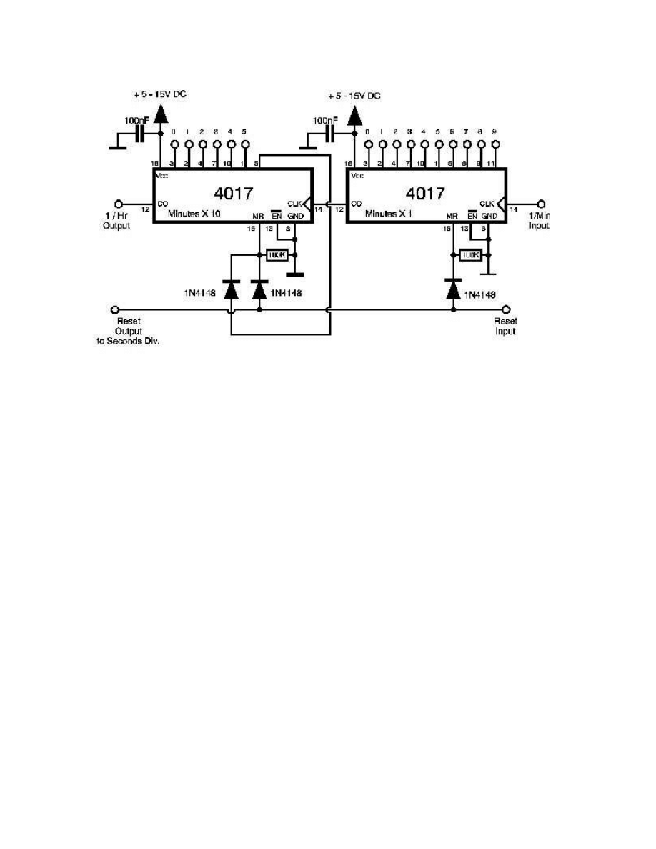
Divider - but the In and Out is named different. Functionally they are alike.
Now comes a tricky part. In Europe (where I live) we have a 24-hours display. We're not
"AM/PM" guys over here. 24 is a bit hard to decode, since it is neither a roll-over nor is it just a
single digit rollover. So note the reset-logic here. It is a wired-AND with 2 NPN-transistors that
pull the Master Reset up when a "4" appears in the LSB while there is a "2" on the MSB hours
display. Neat, eh ?
My Nixie Clock Project
http://www.mcamafia.de/nixie/ncp_en/ncp.htm
9 von 17
28.01.2013 12:49
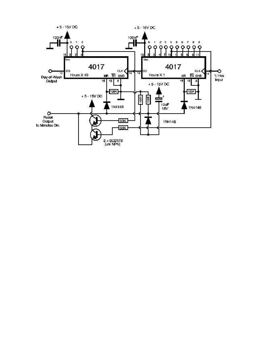
Also note the 10 µF capacitor, the 1N4148 diode and the 100K resistor. These three form the
"Power-On Reset" circuit that pulls the Master Reset line up for some time after a power on
occured to bring the counters to all-Zero displays. It might be unneccessary - but you never know
with these CMOS counters.
The carry-out signal from the last counter might be used to create a "Day of Week" display with
another 4017 and e.g. a backlighted frontpanel. Be creative.
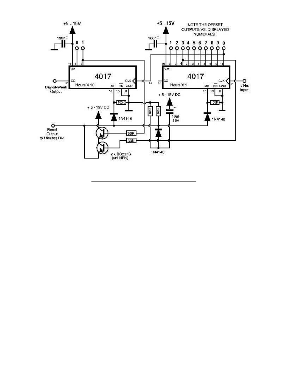
If you decide to have "US-style" AM-PM display you will have to slightly modify the hours
divider.
The counting on the hours display does not start at 00:00 but at 01:00. All numerals need an offset.
The Q0 output sets the "1", the Q1 output the "2" and so forth. Due to that you have to move the
input of the 10-hours from the "Carry Out" (pin 12) to the pin 11, which advances the 10-hours
with every transition from "9" to "0".
While the counting resets at one minute after "12:59" at "13" in the hours display (and not at "24"
after "23:59") you need to alter signal for the Wired-AND to the reset the hours stage to pin 2 on
the 10-hours and pin 4 on the 1-hours.
My Nixie Clock Project
http://www.mcamafia.de/nixie/ncp_en/ncp.htm
10 von 17
28.01.2013 12:49
More power: Driving the Nixies
Problem with the Nixies is the relatively high voltage they operate with. Each cathode pin that is
not grounded is pulled up due to the electron migration inside the gas-filled tube to near the anode
voltage U
a
. This may be 140 VDC - or above on some types. A circuit that pulls down a cathode
from this "idle voltage" to GND must be capable to handle it. If you use a NPN transistor the
Emitter (E) is tied to GND and the Collector (C) is connected with one of the cathode pins. The
Base (B) is connected to the counter outputs via an appropriate current-limiting resistor. The
"Collector / Base Voltage with open Base" U
cb0
specs for the transistor must be higher than the
idle voltage on the cathodes. That's the voltage a transistor can handle when being not conductive
(= not switched on). This disqualifies most common transistors, since their U
cb0
is only 15 - 60
Volts.
But - there are matching transistors available. Namely those designed for TV-purposes (video
stage, color final stage, deflection circuits) or various HF and switching transistors can be used. If
you have access to a listing of transistors with their base data you will easily find some matching
types. Most common and low-cost transistor is the MPS-A42, which is a NPN transistor with U
cb0
= 300 V, I
c
= 0.5 Amp and P
tot
= 0.625 Watts designed for TV video stages. In Germany we pay
0.08 Euro (about 7 cents) for one - comes cheaper if you buy 100 for example.
Also useable are BF118, BF179C, BF259, BF338, BSS48, BUW37 (all with a metal-can case) or
BF413, BF420A, BF422A, BF483 (plastic case), AT1, AT2, DC or NMPSA-42 (SMD types) to
name a few.
My Nixie Clock Project
http://www.mcamafia.de/nixie/ncp_en/ncp.htm
11 von 17
28.01.2013 12:49
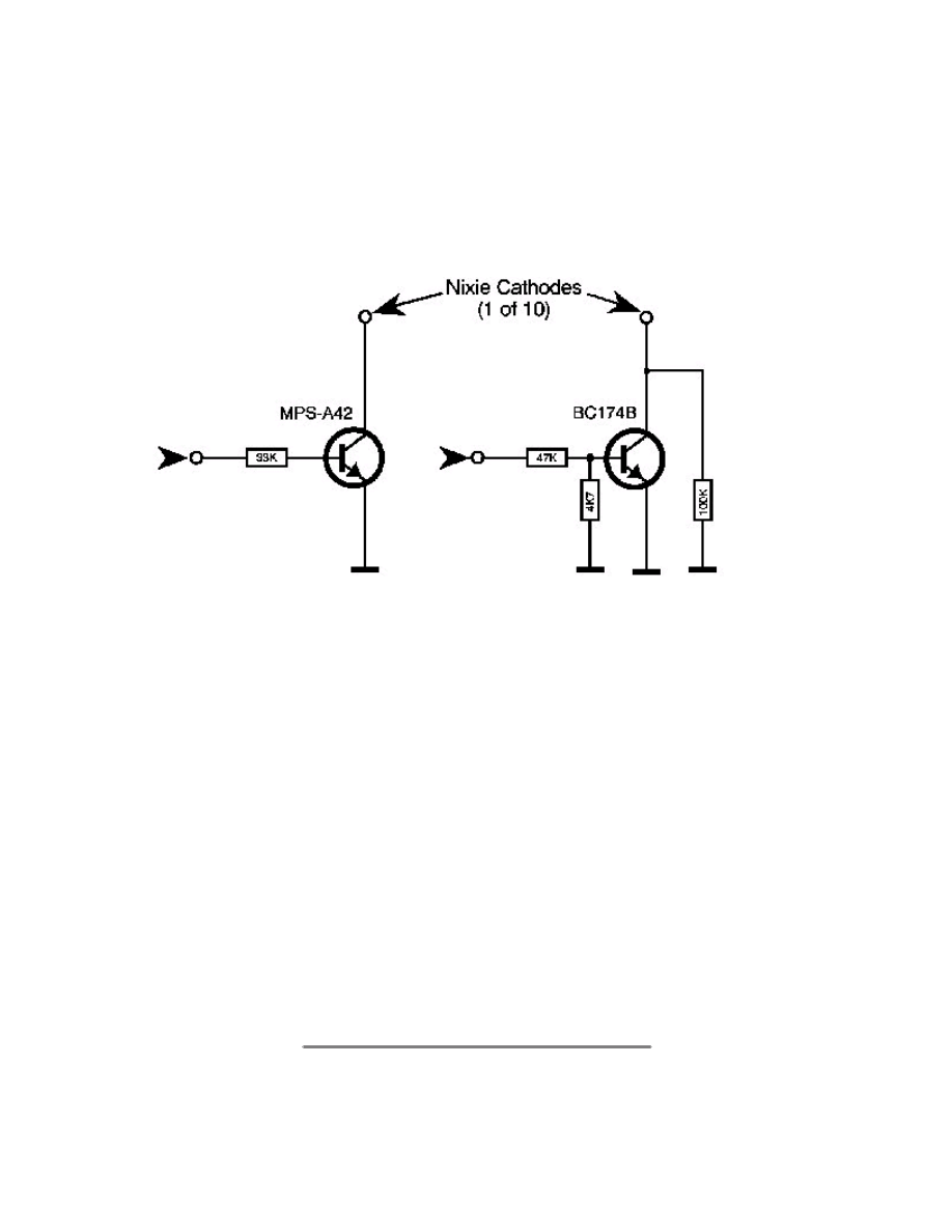
Alternatively you could tie down all cathodes to GND with a resistor of 100 KOhms to reduce the
idle voltage - without starting the cathodes to glow already. In this case a more versatile transistor
with a U
cb0
of least 65V like the BC174B or BC546 or BC846 should do. However - you need 3
times more resistors.
The schematic below explains the different driver circuits.
The left circuit is the pure simplicity: only one 33 K resistor between the counter output and the
base of the transistor. While in the circuit on the right you have an additional voltage divider with
a 47 K / 4.7 K resistor between the counter output and the base plus an additional 100 K "pull
down" resistor that reduces the voltage between the turned-off cathode and GND.
To tell the truth: I didn't bother much with the circuit on the right side. In fact I got the idea from
an old TV program display circuit that uses Nixie tubes. But the MPS-A42 transistors are fairly
cheap and there's no need to switch to some low(er) voltage types, which aren't much cheaper - if
at all. But maybe you happen to have several hundreds of them around ... feel free to use them.
The circuit itself is simple: the positive signal from the counter output passes the current-limiting
33 K resistor and turns on the Collector-Emitter path, which then grounds the cathode pin of the
nixie. This turns on the neon glow for that cathode.
Under Control: Switches for setting the clock
Since this clock is only a counter it does not get the time "by automatic". However: since it has
My Nixie Clock Project
http://www.mcamafia.de/nixie/ncp_en/ncp.htm
12 von 17
28.01.2013 12:49
"Auto-Zero" function you could try plug it in at midnight exactly ...
So we need switches. I like clocks where minutes and hours can be set independently. And which
has not to cycle through the entire 24-hours-counting in fast forward and then set the "finetuning"
with a slow mode switch. I prefer setting the minutes, then the hours. Once I goof on that I don't
need to re-run once again. And again. Maybe.
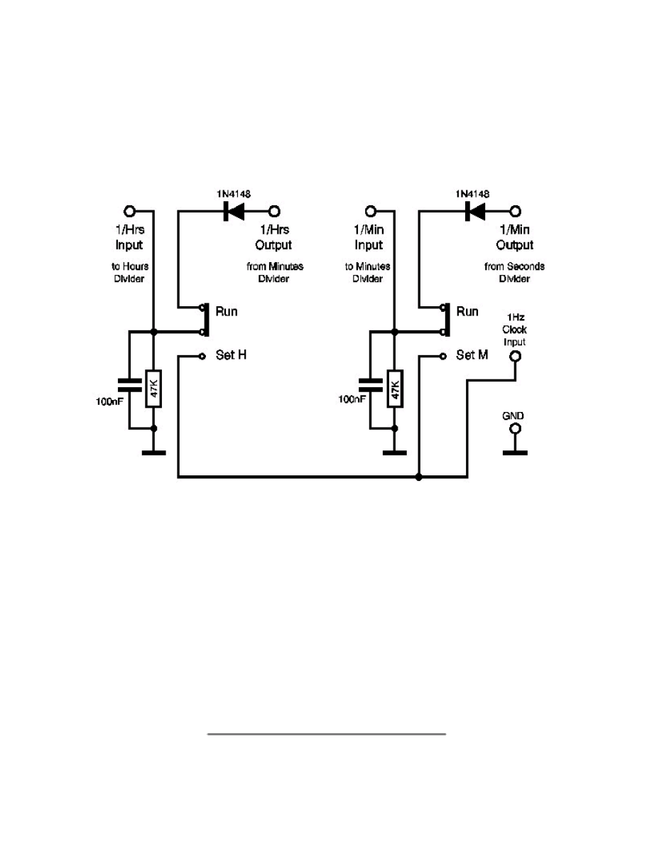
The solution is pretty simple. Two toggle switches, one between the seconds and minutes divider
and one between the minutes and hours divider will do the trick. Look here:
The common contact on either switch is connected to the input of the counter to set (minutes or
hours). The resistor / capacitor combination debounces the switch a bit to avoid "scrolling" when
switching back from set to run mode.
The upper (NC - now closed) contact is connected with the output of the previous counter. The
Diode is for decoupling. It is not always neccessary, but might help avoiding problems, when the
switch has "take-over" contacts that close both contacts momentarily while toggling.
The lower (NO - Now open) contact is connected with the 1 Hz base clock from the
1Hz-Generator. If the clock is too slow for your feel (especially on the minutes count-up) feel free
to use the 2 Hz from the Pin 3 (Q13) of the 4060 directly or even use the 4 Hz signal that can be
generated from pin 1 (Q11) of the 4060 and the second half of the 4013 Flip-Flop. Or use pin 2
(Q12) on the 4060, which offers 4 Hz already.
Ticking the seconds: A blinking colon
My Nixie Clock Project
http://www.mcamafia.de/nixie/ncp_en/ncp.htm
13 von 17
28.01.2013 12:49
Those who opted to build a 4-digit clock with Hours and Minutes only (and save 16 transistors and
16 resistors at least) may wish to have something that indicates the seconds pacing on. Analogous
to the odd blinking ":" on other digital watches.
Easy done. If your Nixie has a decimal point you could use one of those. Nixies that have a
decimal point to the right of the number should use the one in the 1 / Hours digit (LSB), with a
left-side decimal point you use the one in the 10 / Minutes digit (MSB). No special treatment
required. The anode current on the Nixie goes up a bit - but that shouldn't harm anything.
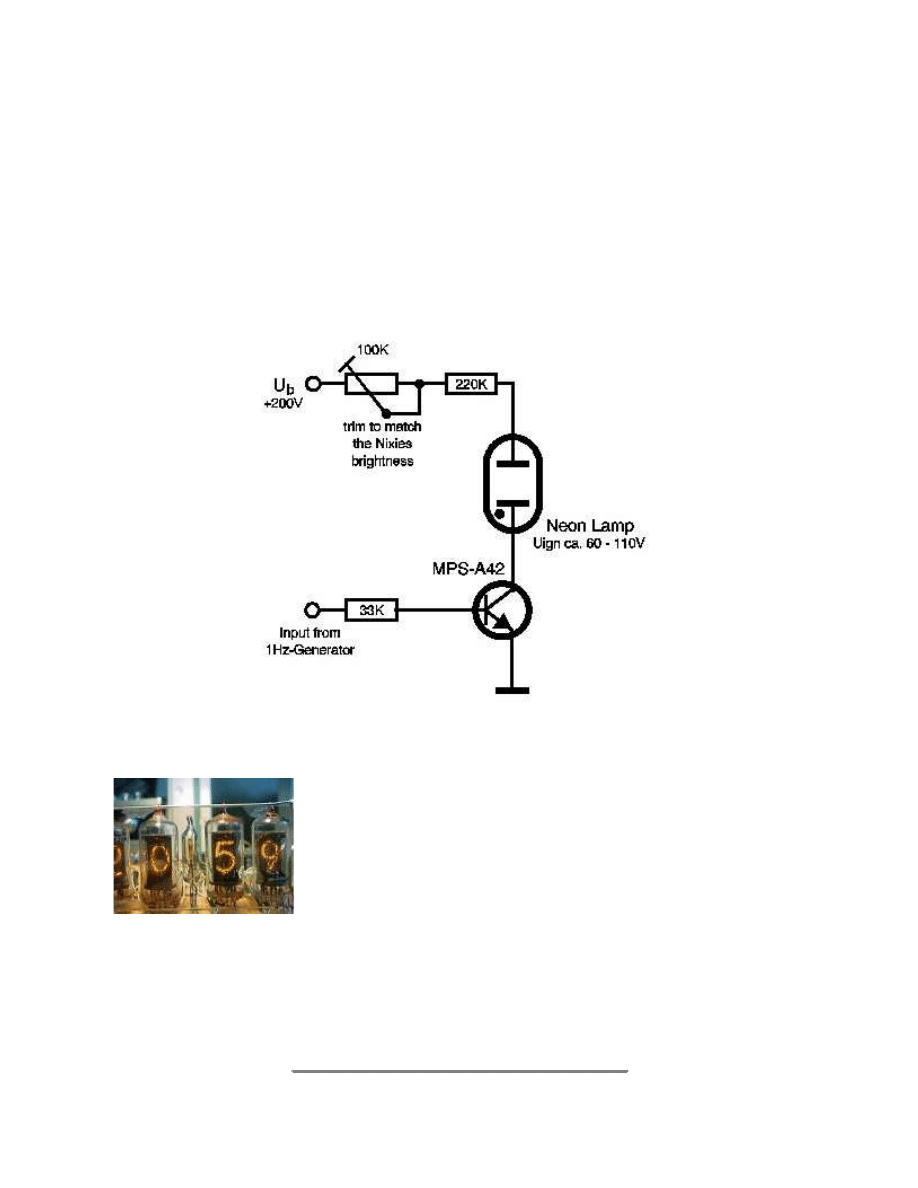
Those who use Nixies without decimal points or aren't attracted much by the look may use a single
neon-lamp in the middle between the hours and minutes display. See the schematic below.
This is how the single, middle flashing neon lamp looks on my second
prototype: it is a relatively long and slim lamp I recovered from some
electronic crap in the early 70s ... almost 3 decades later it came handy
to act as a blinking colon in a home-made Nixie Clock. Life is funny.
You could also use a LED - or some "Magic Eye" tube that alters
height / angle during the seconds ticking. But "real tubes" require a
heater supply which is several 100 mA normally - while the entire circuit with the 8 CMOS chips,
the driver transistors and such takes less than 10 mA. The Nixies take another 5 mA from the 220
V supply - and that's all. If you stuff in a "radio tube" you will have to extend both: your low-volt
and high-volt supply as well. So far you come away with about 6 Watts electric energy - given that
the two transformers have an efficiency of about 80 %.
Bells and Whistles: Adding extra-functions
My Nixie Clock Project
http://www.mcamafia.de/nixie/ncp_en/ncp.htm
14 von 17
28.01.2013 12:49
(Not yet fully approved)
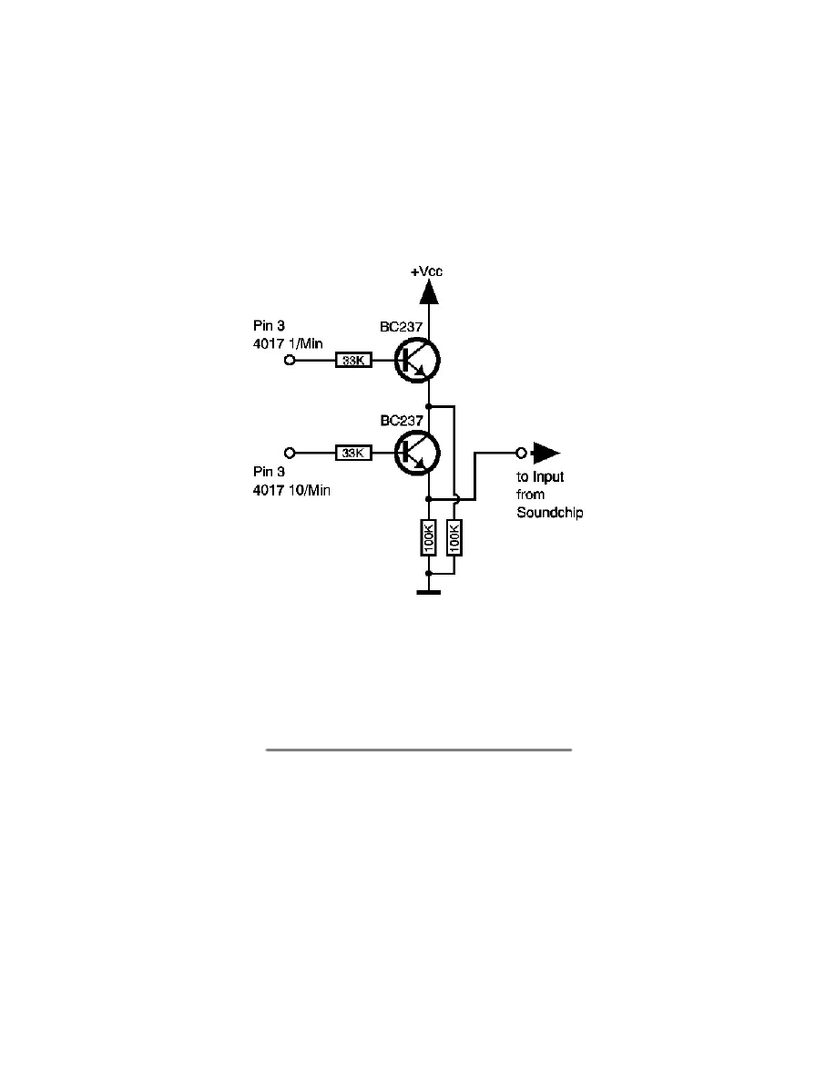
An easy method to add an extra function is using an integrated sound circuit. Usually these chips
are positive-edge triggered. Means: you pull the input high and the sound plays. Given you got a
chip with a "Big Ben" bell tone you simply add an AND-gate output (or two transistors as for the
"Hours" reset circuit) to the sound-chip "activate" input. The AND-gate input is connected with
the "0" outputs (pin 3) on the minutes divider 4017s.
Result: any full hour when the display jumps to "00" in the minutes the sound is triggered.
Hint: include a switch to shut off the sound. Sometimes these "good" ideas turn out to be
somewhat ennerving on the long run. (Big Grin !).
Finally: some pictures from my prototypes
So far I made three different prototypes. After some testings and trials the circuit has stabilized to
the components shown above. There is however a lot room for improovements or changes,
add-ons and whatnot. Especially the switches for setting the time are subject to permanent change.
A printed circuitboard is also (yet) missing, but I'm working on it.
Here are some pictures of the two working clocks.
My Nixie Clock Project
http://www.mcamafia.de/nixie/ncp_en/ncp.htm
15 von 17
28.01.2013 12:49
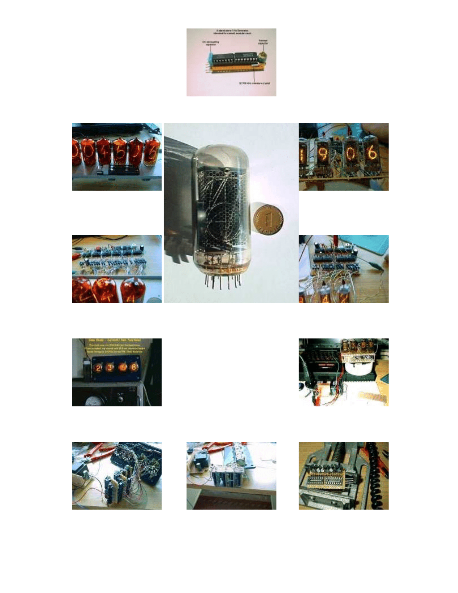
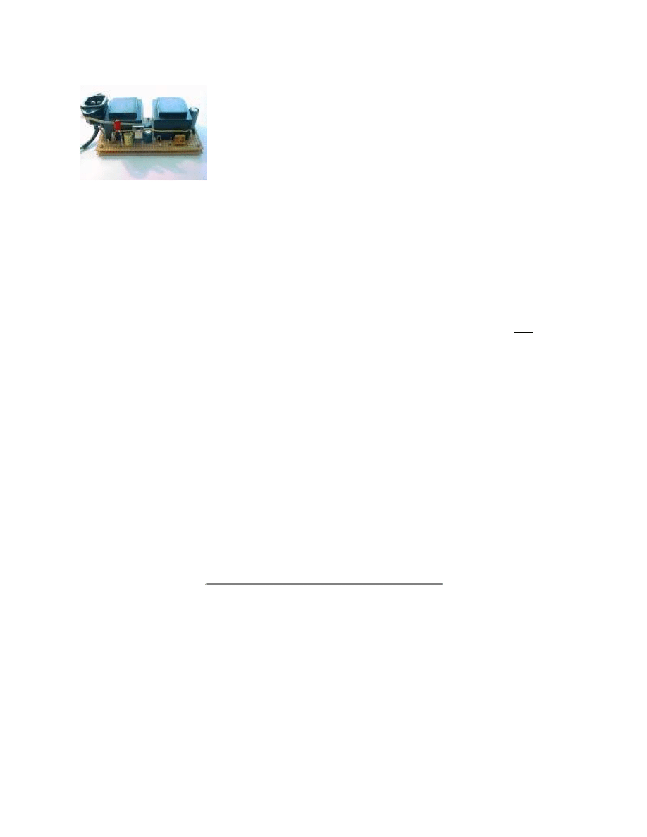
The 1Hz generator.
Built as sample, used in "Study" clock.
6 x ZM1040 in red.
30mm character height.
Mounted 30° to the right.
Rail was for ZM1020 originally.
Originally this was a ZM1040
which used to have a red
filter coating.
I removed it for better look.
The ZM1042 is the clear glass version.
Still without the neon lamp
in the middle.
The Nixies were ZM1080,
but I removed the red filter.
A standard sized Euro-Board.
The red LED takes more
power than all the chips.
The "air-wires" phase.
Switches not installed.
A case study with 4 x Z5600M.
(ex-GDR ZM1020-equivalents)
Just completed.
Stacked board and display.
Different switches now.
Not enough room ?
Build it compacter.
That's how I did it.
Everything on very
small boards. To fit in
the "Study" case.
A divider / driver circuit.
Very compact built.
One of two.
My Nixie Clock Project
http://www.mcamafia.de/nixie/ncp_en/ncp.htm
16 von 17
28.01.2013 12:49
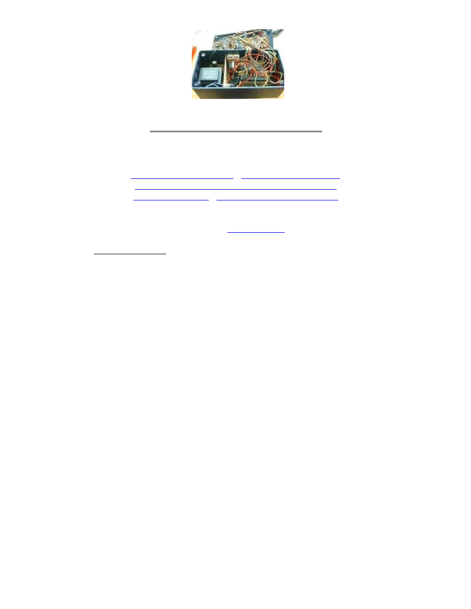
A look inside.
Yes - it is pretty tight filled..
Other related Topics:
My Nixie Tube Mini-Tester
-
My Little Nixie Collection
A "7-Segment-To-Nixie" Decoder (very strange thing)
Dimming the Nixies
-
A Nixie Clock For Everyone ... !
© 2001 by
Peter H. Wendt
Maintainer Notes: all tips given in this document are without any warranty.
If you accidently kill yourself, burn the house or blow everything - your problem.
Switch your brain on, think, reconsider and then act. But first: Think !
You may however pick anything you like from this page if you quote the original source.
Feel free to leave me a note, reports, pictures or ask questions if you like.
I try to respond if my time allowes, which is not always the case.
Sorry. I have a lot hobbies and a job.
My Nixie Clock Project
http://www.mcamafia.de/nixie/ncp_en/ncp.htm
17 von 17
28.01.2013 12:49
Wyszukiwarka
Podobne podstrony:
activity sheet my grandfather s clock
My Project Planner
My Project Planner
3rd Project My family moves to another city ESL 3
Prezentacja ZPR MS Project
my clothes
biologia my
christiane f my dzieci z dworca zoo PODRYX5ASFIPH4SUR3JRHNPGY3OISOG2VG3DIII
Free Energy Projects 2
Microsoft Office Project Project1 id 299062
M Swieciaszek Task 2 my comment (2)
Spis przetw, my hobby, moje przepisy
my biography, opracowania tematów
project
My górnicy
89SXX Project Board
light my fire
Classic Battletech Technical Readout Project Omega
30 LED Projects
więcej podobnych podstron