EN
GLISH
FRANCAIS
DEUTSCH
ESPAÑOL
IT
AL
IANO
日本語
Drop Ceiling Mount
Installation Guide

Drop Ceiling Mount Installation Guide
EN
GLISH
This installation guide provides instructions for installing the Drop Ceiling Mount for the AXIS
225FD Fixed Dome Network Camera. Read the entire guide before attempting installation.
For all other aspects of using the camera, please see the User’s Manual, available from
www.axis.com or in the Axis Installation CD.
Package contents
• Ceiling bracket
• Drop Ceiling Mount Installation Guide (this document)
• Template
• 3 Mounting screws
• 2 Tamper-proof screws
• 1 Allen key
• Cover plate
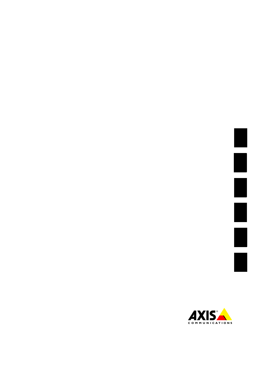
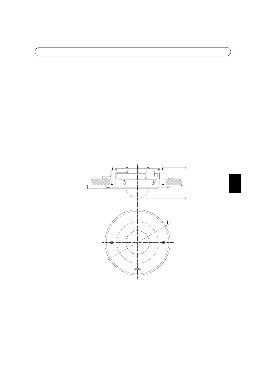
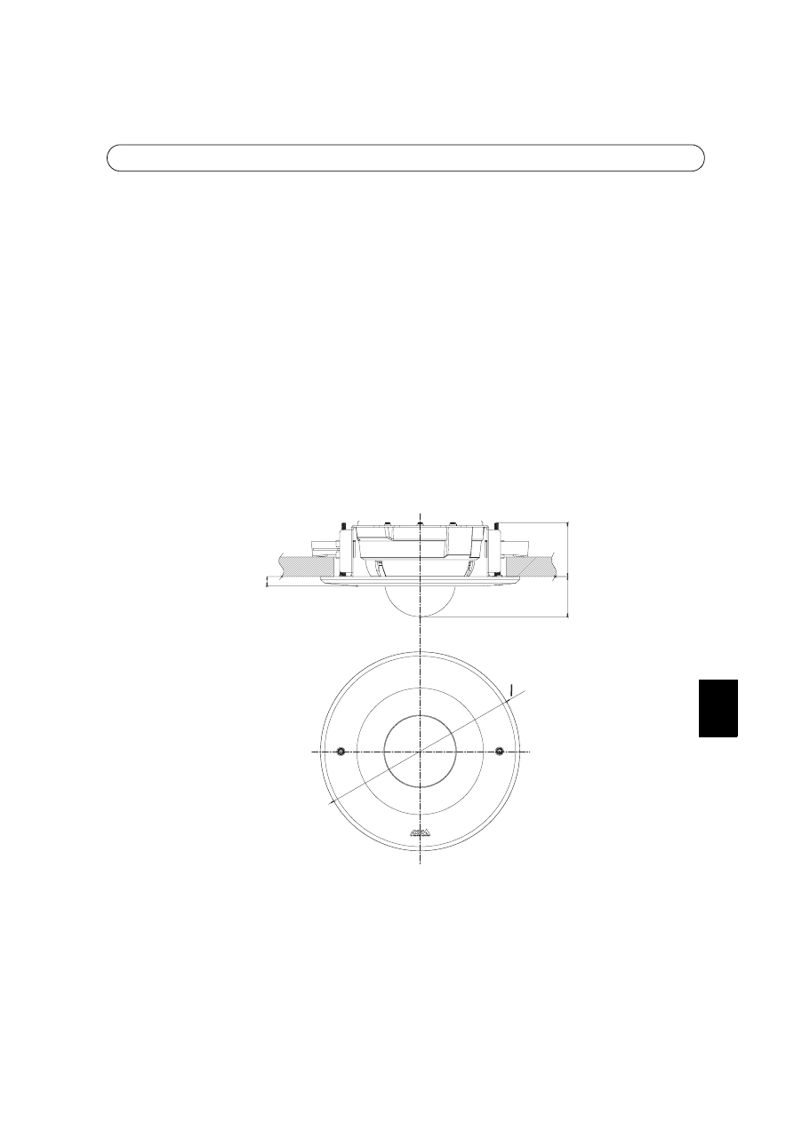
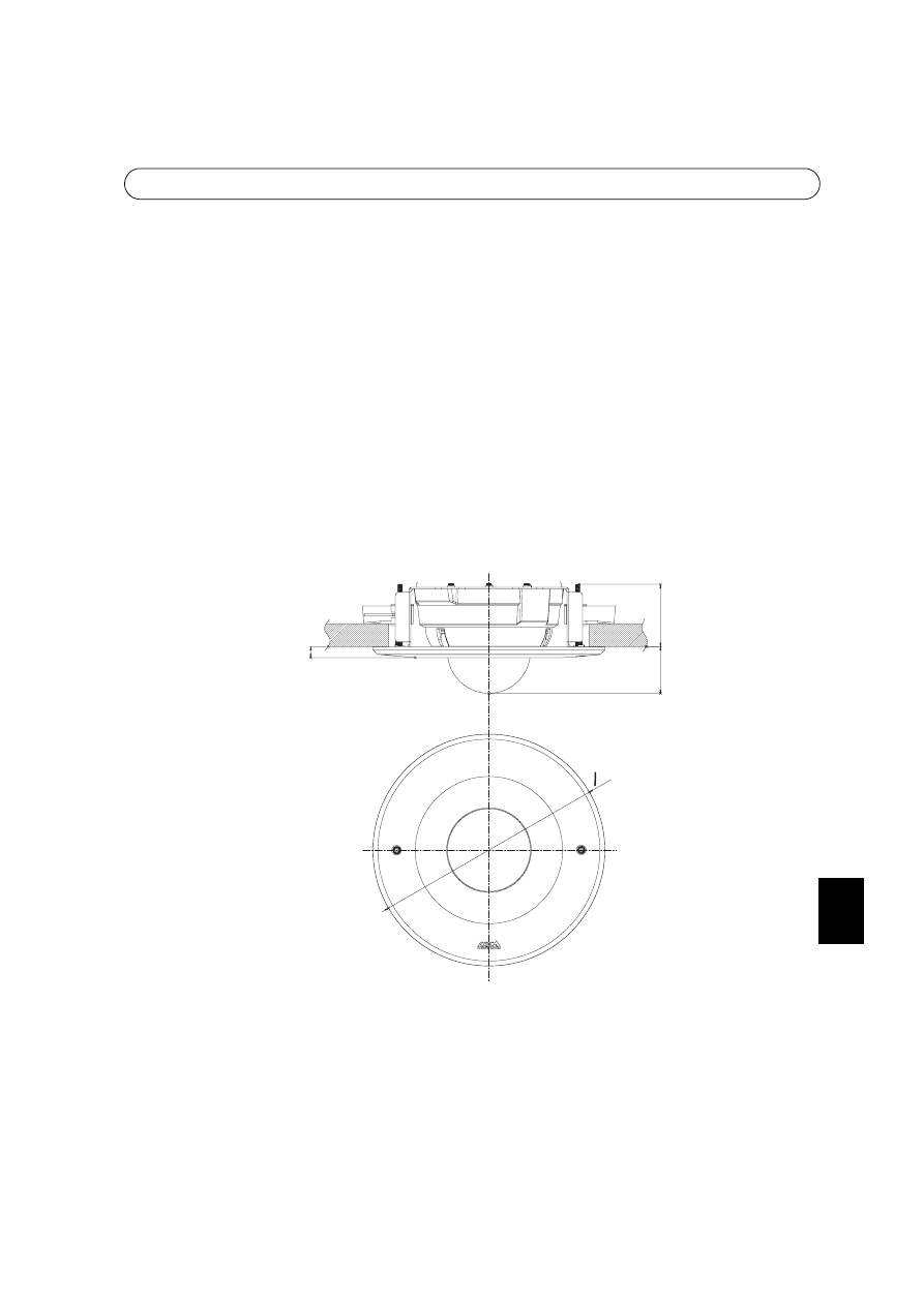
Specifications
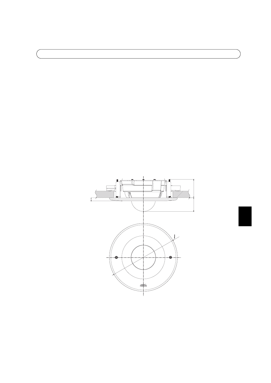
Mass: 850g.
Dimensions: See figure above.
Allowed ceiling thickness: 5 - 40mm
Ceiling hole diameter: 220mm (max 230mm)
13
70
52
0255
13

Drop Ceiling Mount Installation Guide
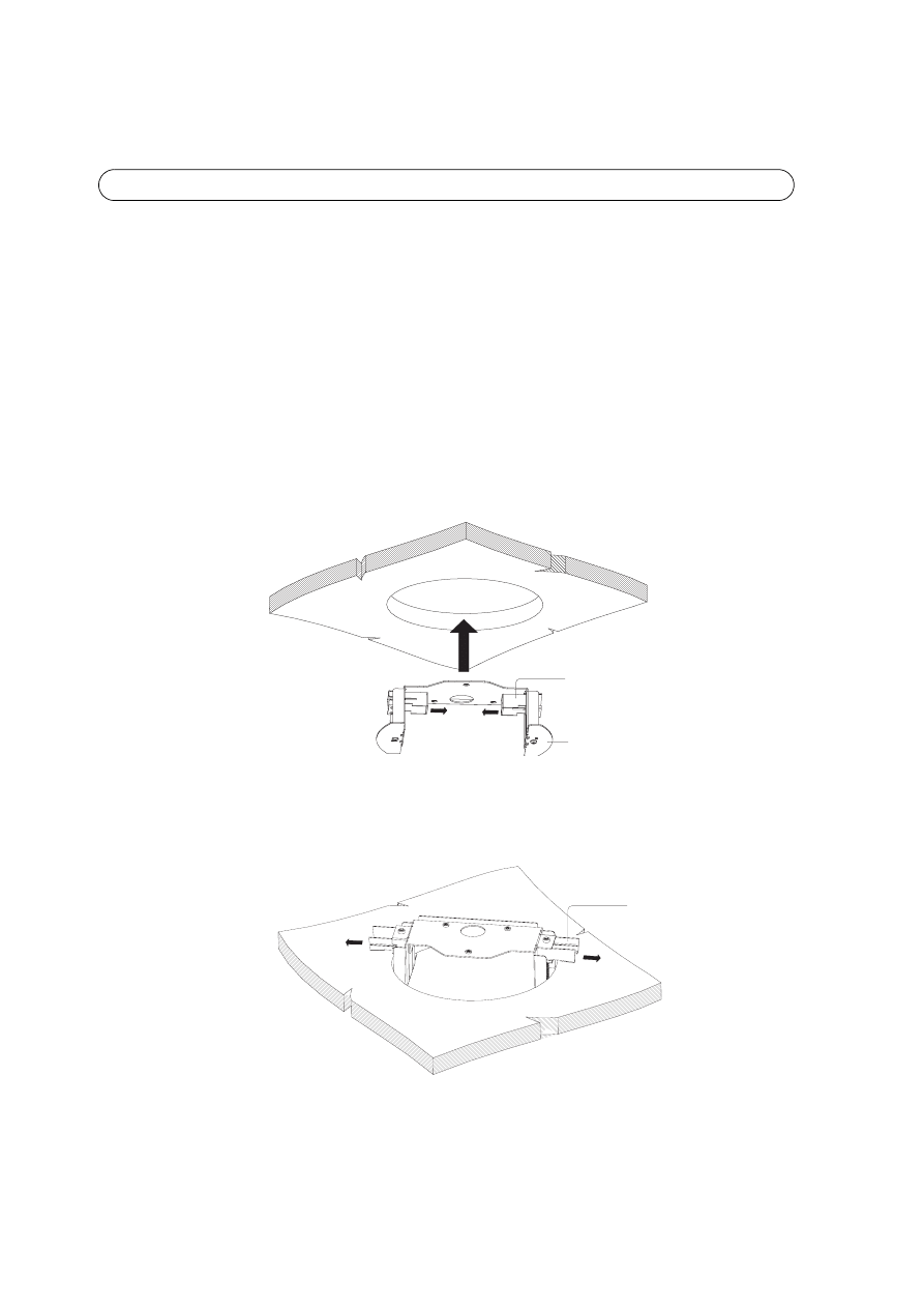
Follow these instructions to install drop ceiling mount:
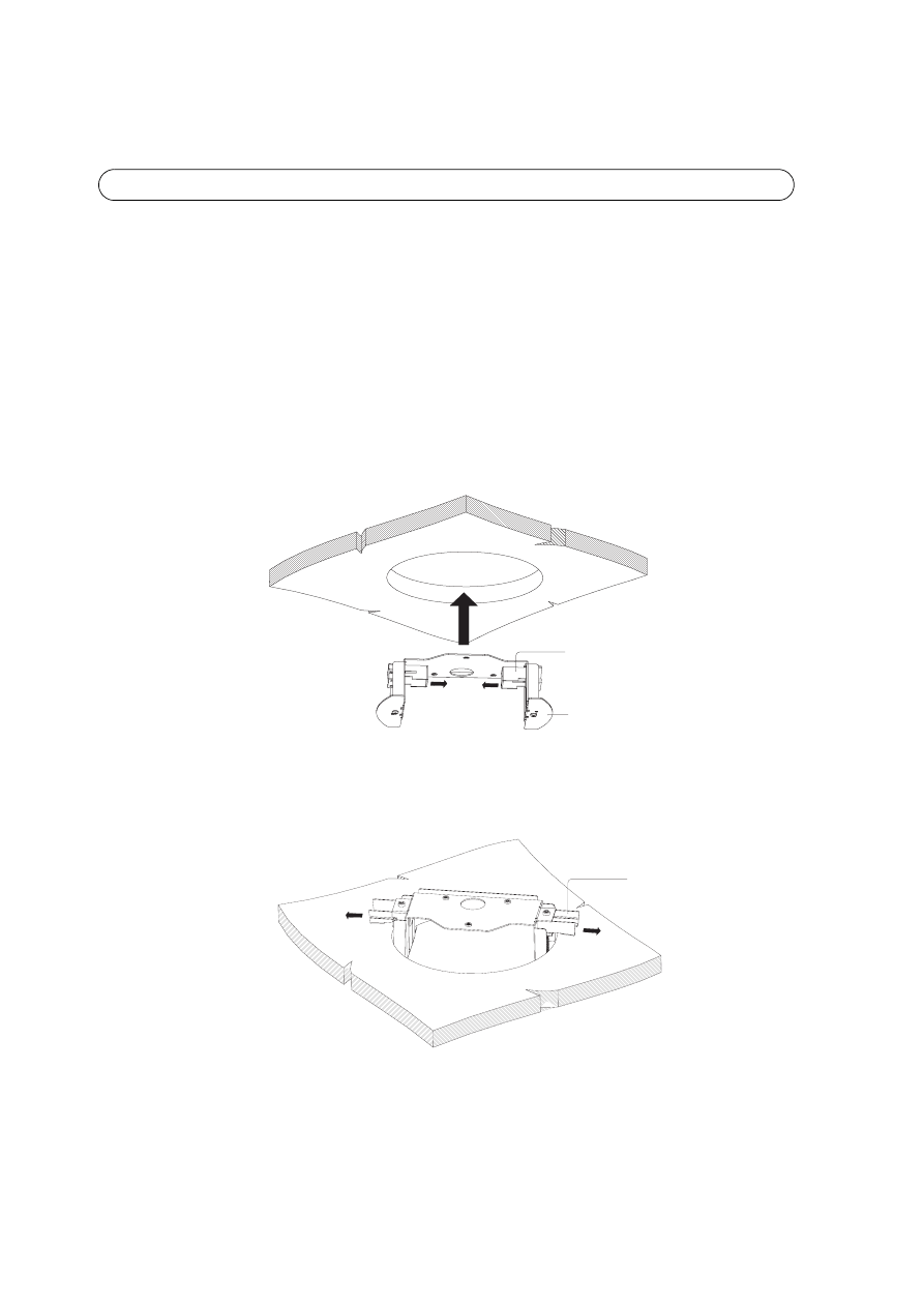
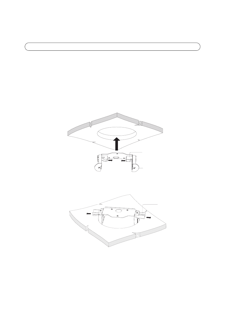
1. Locate the position in the ceiling for a 220mm hole to be cut. A template is included to
aid in cutting the mounting hole. Remove protective paper, fix to ceiling and cut around
template.
Note:
Check that the ceiling material is sturdy enough to hold the gross weight of the camera and the Drop Ceiling
Mount. The thickness of the ceiling should be between 5 and 40mm.
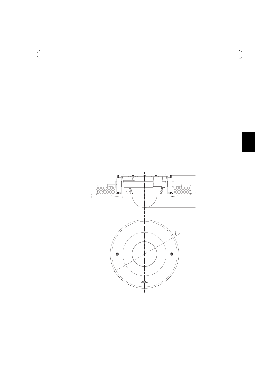
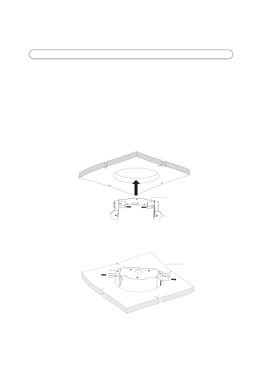
2. Insert the ceiling bracket into hole. The two support arms should be positioned inside the
bracket to ease placement.
3. Push out the support arms completely so that they hold onto the ceiling and the camera
can be inserted into the bracket.
Support
Ceiling bracket
Support arms
Drop Ceiling Mount Installation Guide
EN
GLISH
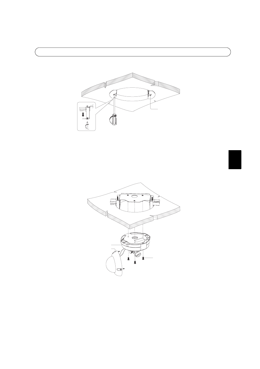
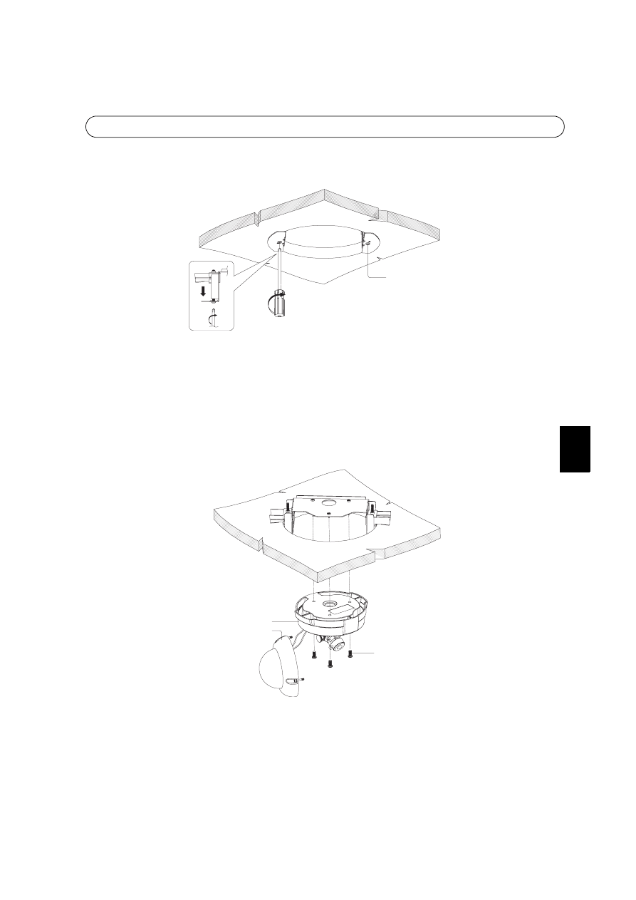
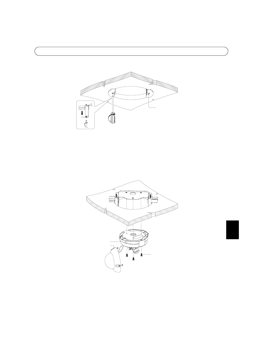
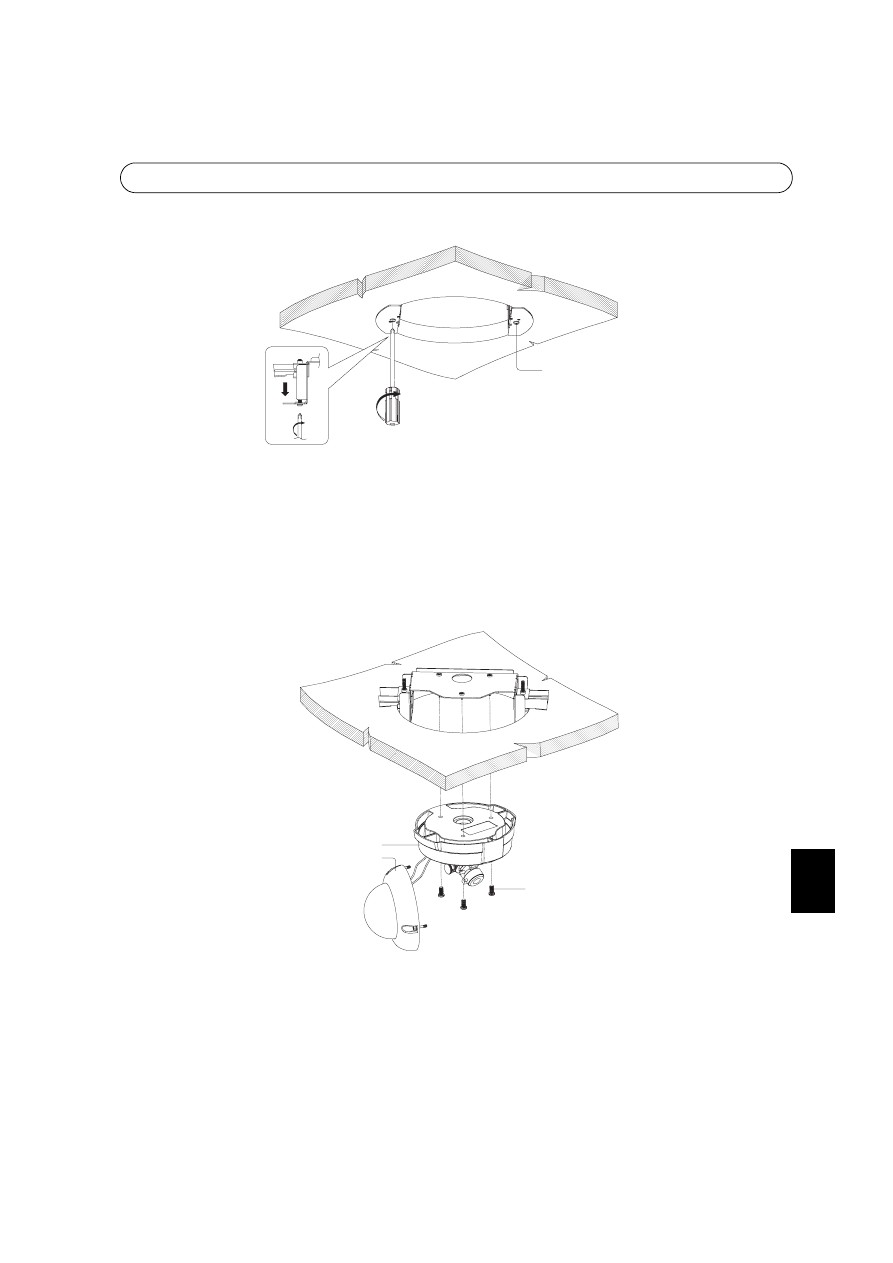
4. Tighten the fixed screws from the bottom to secure the bracket to the ceiling.
Note:
Tightening the fixed screws too hard may cause damage to the ceiling or ceiling bracket.
5. Remove the dome casing from the unit casing. Refer to the AXIS 225FD Installation
Guide.
Note:
Be careful not to damage the dome or scratch the glass.
6. Attach the unit casing to the ceiling bracket using the three mounting screws.
7. Attach dome casing to the unit casing. Refer to the AXIS 225FD Installation Guide.
Fixed screws
4
Mounting screws
Unit casing
Dome casing

Drop Ceiling Mount Installation Guide
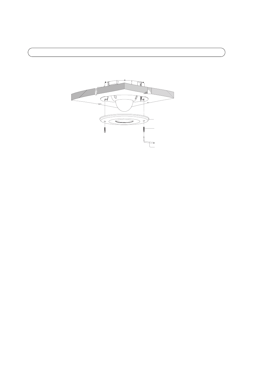
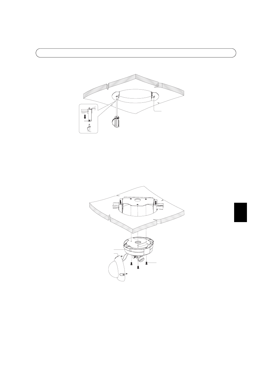
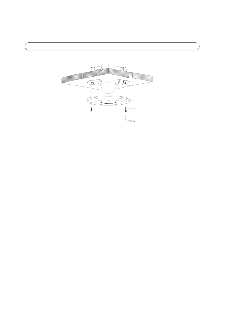
8. Attach the cover plate to the bracket using the two tamper-proof screws and supplied
allen key.
Cover plate
Tamper-proof screws
Allen key
Guide d’installation du montage sur faux-plafonds
FRANÇAIS
FRANCAIS
Ce guide d’installation vous explique comment installer le montage pour faux-plafonds de la Caméra
réseau à dôme fixe AXIS 225FD . Lisez ce guide dans son intégralité avant de procéder à l’installation.
Pour d’autres informations sur l’utilisation de la caméra, consultez le Manuel de l’utilisateur disponible
sur le CD d’installation ou surfez sur www.axis.com.
Contenu de l’emballage
• Support pour plafonds
• Guide d’installation du montage pour faux-plafonds (ce document)
• Gabarit
• 3 vis de montage
• 2 vis inviolables
• 1 clé Allen
• Plaque couvercle
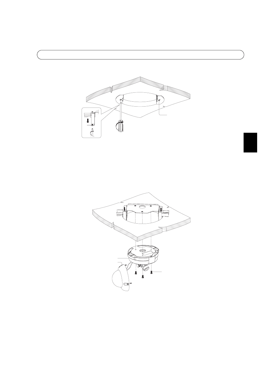
Spécifications
Poids : 850 g.
Dimensions : voir la figure ci-dessus
Épaisseur autorisée du plafond : 5 – 40 mm
Diamètre du trou au plafond : 220 mm (230 mm max.)
13
70
52
0255
13
Guide d’installation du montage sur faux-plafonds
Suivez ces instructions pour le montage sur faux-plafonds :
1. Localisez le point de perforation d’un trou de 220 mm dans le plafond. Un gabarit est
joint pour faciliter la découpe du trou de montage. Retirez le papier de protection, fixez
le gabarit au plafond et découpez tout autour.
Remarque :
Vérifiez que le plafond est assez résistant pour supporter le poids brut de la caméra et du montage pour
faux-plafond. Le plafond doit avoir une épaisseur comprise entre 5 et 40 mm.
2. Introduisez le support dans le trou. Les deux bras support doivent être placés à l’intérieur
du support pour faciliter le montage.
3. Sortez complètement les bras support en les poussant afin que le plafond les retienne et
que la caméra puisse être introduite dans le support.
Bras support
Support pour
plafonds
Bras support
Guide d’installation du montage sur faux-plafonds
FRANÇAIS
FRANCAIS
4. Serrez les vis fixes à partir du bas pour fixer le support au plafond.
Remarque :
Ne pas forcer pour ne pas endommager le plafond et le support pour plafonds.
5. Retirez le boîtier du dôme du boîtier de l’appareil. Reportez-vous au Guide d’installation
de l’AXIS 225FD.
Remarque :
Veillez à ne pas endommager le dôme ni à rayer la vitre.
6. Fixez le boîtier de l’appareil au support du plafond à l’aide des trois vis de montage.
7. Fixez le boîtier du dôme au boîtier de l’appareil. Reportez-vous au Guide d’installation
de l’AXIS 225FD.
Vis fixes
4
Vis de montage
Boîtier de l’appareil
Boîtier du dôme
Guide d’installation du montage sur faux-plafonds
8. À l’aide des deux vis inviolables et de la clé Allen fournie, fixez la plaque couvercle au
support.
Plaque couvercle
Vis inviolables
Clé Allen
Installationsanleitung für Deckenhalterung
DEUTSCH
DEUTSCH
Diese Anleitung enthält Anweisungen zum Installieren der Deckenhalterung für die Netzwerkkamera für
Festinstallation mit Kuppelhaube, AXIS 225FD. Lesen Sie die komplette Anleitung, bevor Sie mit der
Installation beginnen.
Alle anderen Aspekte der Nutzung dieser Kamera werden im Benutzerhandbuch beschrieben, das sich
auf der mitgelieferten Axis Installations-CD befindet. Sie können das Benutzerhandbuch auch von
unserer Website www.axis.com herunterladen.
Lieferumfang
• Deckenhalterung
• Installationsanleitung für Deckenhalterung (dieses Dokument)
• Vorlage
• 3 Montageschrauben
• 2 zugriffssichere Schrauben
• 1 Schraubenschlüssel
• Abdeckung
Technische Daten
Gewicht: 850 g
Abmessungen: siehe Abbildung oben
Zulässige Deckendicke: 5 - 40 mm
Durchmesser der Deckenöffnung: 220 mm (max. 230 mm)
13
70
52
0255
13
Installationsanleitung für Deckenhalterung
So installieren Sie die Deckenhalterung:
1. Bestimmen Sie die Position an der Decke, wo eine Öffnung mit 220 mm Durchmesser
entstehen soll. Eine im Lieferumfang enthaltene Vorlage erleichtert Ihnen das
Ausschneiden der Öffnung. Entfernen Sie das Schutzpapier der Vorlage, und bringen Sie
sie an der Decke an. Schneiden Sie um die Vorlage herum die Öffnung aus.
Hinweis:
Stellen Sie sicher, dass das Deckenmaterial das Gewicht der Kamera und der Deckenhalterung tragen kann.
Die Decke sollte zwischen 5 und 40 mm dick sein.
2. Führen Sie die Deckenhalterung durch die Öffnung. Die beiden Halterungsbügel sollten
nach innen zeigen, um die Anbringung zu erleichtern.
3. Damit die Halterung arretiert ist und Sie die Kamera anbringen können, müssen Sie die
Halterungsbügel nach beiden Seiten vollständig herausziehen.
Halterungsbügel
Deckenhalterung
Halterungsbügel
Installationsanleitung für Deckenhalterung
DEUTSCH
DEUTSCH
4. Ziehen Sie die befestigten Schrauben von unten fest, um die Deckenhalterung fest an der Decke
anzubringen.
Hinweis:
Wenn Sie die Schrauben zu fest anziehen, kann dadurch die Decke oder die Deckenhalterung beschädigt
werden.
5. Nehmen Sie die Kuppelhaube vom Kameragehäuse ab. Anweisungen hierzu finden Sie in der
AXIS 225FD-Installationsanleitung.
Hinweis:
Achten Sie darauf, dass die Kuppelhaube nicht beschädigt wird und das Glas keine Kratzer bekommt.
6. Befestigen Sie das Kameragehäuse an der Deckenhalterung mit den drei Montageschrauben.
7. Befestigen Sie die Kuppelhaube am Kameragehäuse. Anweisungen hierzu finden Sie in der AXIS
225FD-Installationsanleitung.
Befestigte Schrauben
4
Montageschrauben
Kameragehäuse
Kuppelhaube

Installationsanleitung für Deckenhalterung
8. Befestigen Sie die Abdeckung an der Deckenhalterung. Verwenden Sie hierfür die zwei
zugriffssicheren Schrauben und den beigefügten Schraubenschlüssel.
Abdeckung
Zugriffssichere Schrauben
Schraubenschlüssel
Guía de instalación del soporte para falso techo
ESPAÑOL
ESPAÑOL
Esta guía de instalación contiene las instrucciones para instalar el soporte para el montaje en
falso techo de la AXIS 225FD Cámara de red con burbuja fija. Antes de comenzar la
instalación, le rogamos que lea la guía por completo.
Para obtener información sobre la utilización de la cámara, consulte el Manual del usuario,
disponible en www.axis.com o en el CD de instalación Axis.
Contenido del paquete
• Soporte para techo
• Guía de instalación para el montaje en falso techo (este documento)
• Plantilla
• 3 tornillos de montaje
• 2 tornillos de alta resistencia
• 1 llave Allen
• Placa de la cubierta
Especificaciones
Masa: 850 g.
Dimensiones: Véase la figura anterior.
Grosor de techo máximo: 5 – 40 mm
Diámetro del agujero del techo: 220 mm (máx. 230 mm)
13
70
52
0255
13

Guía de instalación de soporte para falso techo
Siga las siguientes instrucciones para instalar el soporte para falso techo:
1. Ubique en el techo el lugar en el que perforará un agujero de 220 mm. Se incluye una
plantilla para ayudarle a cortar el agujero de montaje. Retire el papel protector, fíjelo al
techo y corte alrededor de la plantilla.
Nota:
Compruebe que el material del techo es lo bastante sólido como para soportar el peso bruto de la cámara y del
soporte para falso techo. Se recomienda un grosor de techo comprendido entre 5 mm y 40 mm.
2. Introduzca el soporte de techo en el agujero. Los dos brazos de soporte se deben colocar
en el interior del soporte para facilitar la colocación.
3. Empuje hacia fuera los brazos de soporte por completo de forma que se agarren al techo
y la cámara se pueda introducir en el soporte.
Brazos de
soporte
Soporte para
techo
Brazos de
soporte
Guía de instalación del soporte para falso techo
ESPAÑOL
ESPAÑOL
4. Apriete los tornillos fijos desde la base para fijar el soporte al techo.
Nota:
Si los aprieta demasiado, podría dañar el techo o el soporte para techo.
5. Retire la carcasa de la burbuja de la carcasa de la unidad. Consulte la Guía de instalación
de la AXIS 225FD.
Nota:
Procure no dañar la burbuja ni rayar el cristal.
6. Inserte la carcasa de la unidad en el soporte para techo mediante tres tornillos de
montaje.
7. Inserte la carcasa de la burbuja en la carcasa de la unidad. Consulte la Guía de
instalación de la AXIS 225FD.
Tornillos fijos
4
Tornillos de montaje
Carcasa de la unidad
Carcasa de la burbuja

Guía de instalación de soporte para falso techo
8. Fije la placa de la cubierta en el soporte mediante los dos tornillos de alta resistencia y la
llave Allen que se incluye.
Placa de la cubierta
Tornillos de alta resistencia
Llave Allen
Guida all'installazione per il montaggio a controsoffitto
Italiano
IT
AL
IANO
Nella presente guida all'installazione vengono fornite le istruzioni per il montaggio a controsoffitto
della videocamera di rete a cupola fissa AXIS 225FD. Leggere l'intera guida prima di iniziare
l'installazione.
Per qualsiasi altro aspetto relativo all'utilizzo della videocamera, vedere il Manuale per l'utente,
disponibile sul sito Web di Axis all'indirizzo www.axis.com oppure nel CD di installazione di Axis.
Contenuto della confezione
• Staffa da soffitto
• Guida all'installazione per il montaggio a controsoffitto (questo documento)
• Modello
• 3 viti di montaggio
• 2 viti antimanomissione
• 1 chiave a brugola
• Piastra di copertura
Specifiche
Peso: 850 g.
Dimensioni: vedere la figura.
Spessore massimo consentito: da 5 a 40 mm.
Diametro foro del soffitto: 220 mm (max. 230 mm).
13
70
52
0255
13
Guida all'installazione per il montaggio a
Per il montaggio a controsoffitto seguire le istruzioni riportate di
seguito.
1. Individuare la zona del soffitto dove praticare il foro di 220 mm. È possibile utilizzare il
modello di foratura fornito. Rimuovere la pellicola di protezione e praticare il foro
applicando il modello al soffitto.
Nota:
Verificare che il materiale del soffitto sia abbastanza solido per sostenere il peso della videocamera e del
controsoffitto. È necessario che lo spessore del soffitto sia compreso tra 5 e 40 mm.
2. Inserire la staffa nel foro praticato nel soffitto. Posizionare le due alette di fissaggio verso
l'interno per inserire la staffa con maggiore facilità.
3. Rilasciare le alette per agganciare la struttura al soffitto e inserire la videocamera nella
staffa.
Alette di
fissaggio
Staffa da
soffitto
Alette di
fissaggio
Guida all'installazione per il montaggio a controsoffitto
Italiano
IT
AL
IANO
4. Fissare la staffa al soffitto stringendo le viti a partire dal basso.
Nota:
Se le viti fisse vengono strette eccessivamente possono verificarsi danni al soffitto o alla staffa.
5. Rimuovere la cupola dall'alloggiamento dell'unità. Vedere la Guida all'installazione di
AXIS 225FD.
Nota:
Fare attenzione a non danneggiare la cupola o graffiare il vetro.
6. Fissare l'alloggiamento dell'unità alla staffa del soffitto utilizzando le tre viti di
montaggio.
7. Collegare la cupola all'alloggiamento dell'unità. Vedere la Guida all'installazione di
AXIS 225FD.
Viti fisse
4
Viti di montaggio
Alloggiamento unità
Cupola

Guida all'installazione per il montaggio a
8. Fissare la piastra di copertura alla staffa utilizzando le due viti antimanomissione e la
chiave a brugola fornita.
Piastra di copertura
Viti antimanomissione
Chiave a brugola
天井取 り 付け用ブ ラ ケ ッ ト イ ン ス ト ールガ イ ド
日本語
こ の イ ン ス ト ールガ イ ド は、
AXIS 225FD
を天井に埋め込んで設置す る ための専用ブ ラ ケ ッ ト の使用方法に
ついて説明 し てい ます。
AXIS 225FD
の使用方法については、 ユーザーズマニ ュ アルを参照 し て く だ さ い。 ユーザーズマニ ュ アルは、
AXIS 225FD
に付属の
CD
に収録 さ れてい ます。 ま た、
Axis
のホームページか ら ダ ウ ン ロ ー ド す る こ と がで
き ます。
パ ッ ケージの内容
•
ブ ラ ケ ッ ト 本体
•
ブ ラ ケ ッ ト イ ン ス ト ールガ イ ド (本書)
•
テ ンプ レー ト
•
ネジ (
3
つ)
•
い じ り 止めネジ (
2
つ)
•
専用レ ンチ (
1
つ)
•
カバープ レー ト
仕様
重量 :
850g
寸法 : 上記の図を参照
対応天井厚 :
5
~
40mm
取 り 付け穴径 :
220mm
(最大
230mm
)
13
70
52
0255
13
天井取 り 付け用ブ ラ ケ ッ ト イ ン ス ト ールガ イ ド
ブ ラ ケ ッ ト 取 り 付け手順
1.
天井穴 (
220mm
) を開け る 位置を決定 し ます。 付属のテ ン プ レー ト の保護シールを剥が し 、 穴を開け る
位置に貼 り 付け ます。 テ ンプ レー ト に沿っ て穴を開け ます。
注意 :
天井の素材が、
AXIS 225FD
と ブ ラ ケ ッ ト を合わせた重量に耐え ら れる こ と を事前に確認 し て く だ さ い。
取 り 付けが可能な天井厚は、
5
~
40mm
です。
参考 :
AXIS 225FD
本体の重 さ は
1250g
(電源アダプ タ を除 く )、 ブ ラ ケ ッ ト の重 さ は
850g
です。
2.
サポー ト アーム をブ ラ ケ ッ ト 内に押 し 込んだ状態でブ ラ ケ ッ ト を天井穴に埋め込みます。
3.
サポー ト アーム を外側に出 し て天井に引っ掛け る よ う に し ます。
サポー ト アーム
ブ ラ ケ ッ ト
サポー ト アーム
天井取 り 付け用ブ ラ ケ ッ ト イ ン ス ト ールガ イ ド
日本語
4.
ブ ラ ケ ッ ト の下部にあ る 固定ネジ を締めて、 ブ ラ ケ ッ ト を天井に固定 し ます。
注意 :
固定ネ ジは強 く 締めすぎ ない よ う に し て く だ さ い。 天井ま たはブ ラ ケ ッ ト 本体を損傷す る こ と があ り ま
す。
5.
ド ーム ケーシ ン グ をユニ ッ ト ケーシ ン グか ら 取 り 外 し ます。 詳 し く は、
AXIS 225FD
ユーザーズマニ ュ ア
ルを参照 し て く だ さ い。
注意 :
ド ーム本体やガ ラ ス部を損傷 し ないよ う 注意 し て取 り 外 し を行っ て く だ さ い。
6.
ユニ ッ ト ケーシ ン グ をブ ラ ケ ッ ト に差 し 込んで、 固定ネジ (
3
箇所) を締め ます。
7.
ド ーム ケーシ ン グ をユニ ッ ト ケーシ ン グに取 り 付け ます。 詳 し く は、
AXIS 225FD
ユーザーズマニ ュ アル
を参照 し て く だ さ い。
固定ネジ
4
固定ネジ
ユニ ッ ト ケーシ ング
ド ームケーシ ング
天井取 り 付け用ブ ラ ケ ッ ト イ ン ス ト ールガ イ ド
8.
カバープ レー ト をブ ラ ケ ッ ト に取 り 付け、 専用レ ンチを使用 し てい じ り 止めネジ (
2
箇所) で固定 し ます。
カバープ レー ト
い じ り 止めネジ
専用レ ン チ


Drop Ceiling Mount Installation Guide v2.0
February 2006
Copyright © Axis Communications AB, 2005-2006
Part No. 26427
Wyszukiwarka
Podobne podstrony:
axis 225fd installation guide
acis 225fd dome casing installation guide
installation guide
04 vpuml installation guide
install guide
Installation Guide
install guide
HP System Management Homepage Installation Guide (September 2008)
gmax tempest install guide
HP System Management Homepage Installation Guide (March 2008)
Installation Guide Licensing gu Nieznany
Installation Guide for WindowsXP
c20h c28h c40h c60h installation guide
installation guide
install guide
Mac OS X Installation Guide
03 bpva installation guide
Installation Guide, Installation guide
Installation Guide, Software Registration Form
więcej podobnych podstron