Atlas Centaur 10 Paper Space Model
Precision Paper Space Models
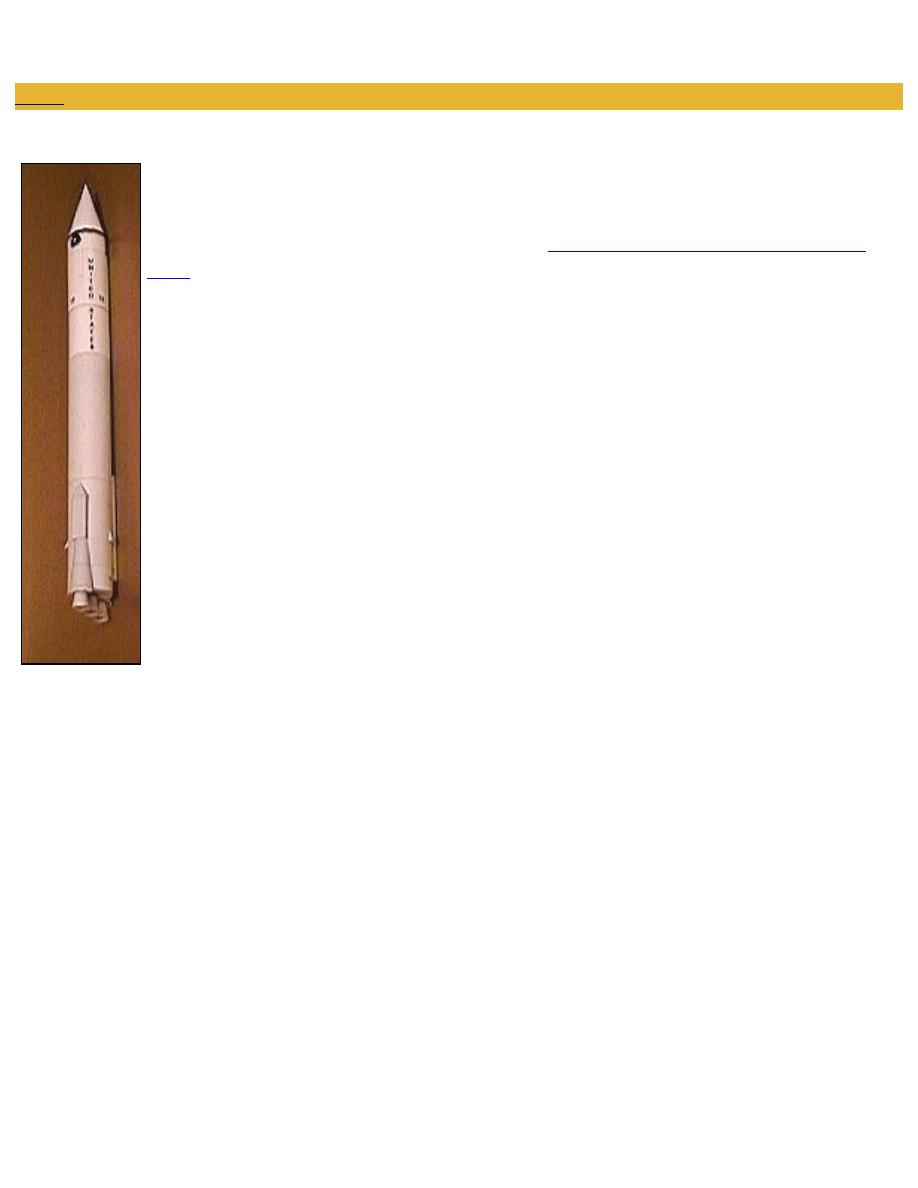
ATLAS CENTAUR 10 LAUNCH VEHICLE
This 1/96 scale Paper Space Model represents Atlas Centaur 10 (AC-10), the rocket that launched
NASA's Surveyor 1 lunar lander from Cape Canaveral Launch Complex 36A on 1966 May 30.
AC-10 was the first operational mission for Centaur, the world's first liquid hydrogen-fueled
rocket stage. The flight followed a difficult, costly,
seven-flight, four year Atlas Centaur test
The six page model can be printed on 20-24 pound paper. Some modelers have reported interesting results using
silver paper for the stainless steel Atlas components. To assemble, you will need a pair of scissors and/or a hobby
knife, rubber cement, white paper glue, a toothpick or narrow strip of paper, a dowel rod or a round pen or pencil,
and some cardstock (ie, several 3 x 5 cards).
The model's Centaur stage is detachable. Forward and aft cardstock bulkheads and double-wrapped tubes create
sturdy Atlas and Centaur bodies. When assembled, the model stands 13.54 inches tall and is 1.25 inches in
diameter.
http://www76.pair.com/tjohnson/ac10ins.html (1 of 5)27-12-2003 19:22:40
Atlas Centaur 10 Paper Space Model
MODEL PAGES
To view and print the model pages, you'll need Adobe Acrobat Reader version 3.0 or later, available free of charge
at
.
Right click on links above to download without opening Acrobat in your browser.
MODEL ASSEMBLY INSTRUCTIONS
This model can be assembled with rubber cement, white paper glue, or a combination of the two. White paper glue
sets faster than rubber cement, but can wrinkle paper. Rubber cement takes longer to set, but the result is usually
stain and wrinkle-free. In the following instructions, the term
"cement" is used whenever rubber cement is thought to be the preferred method. The term "glue" means that white
paper glue should be used.
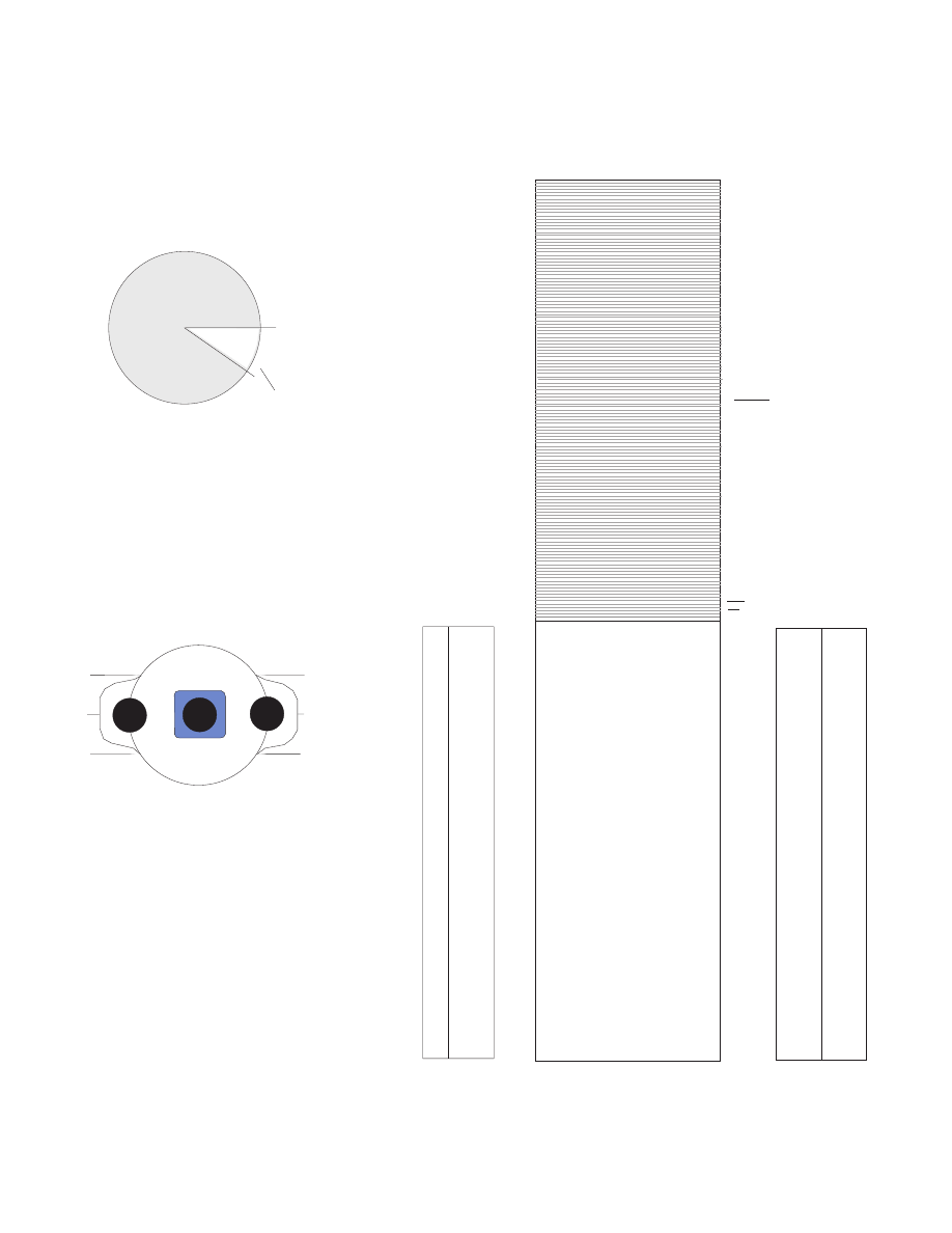
ATLAS (FIRST STAGE) ASSEMBLY
1. Cut out Atlas body and Atlas forward and aft bulkhead
mounts (Page 1). Trace bulkhead mount outlines on
body underfold section on opposite side of page with
pencil. Cement adapter mounts to opposite side of gray
areas, to what will become the inside of the body tube.
2. Roll Atlas body into a double-layered tube without cementing, then apply rubber cement sparingly with
toothpick or small strip of paper at seam only. Use pen or dowel rod inside tube to assist. Clean excess glue with
tissue paper. Finish by gluing loose underfold sections at each end
of the body tube. Use toothpick or small strip of paper to insert glue.
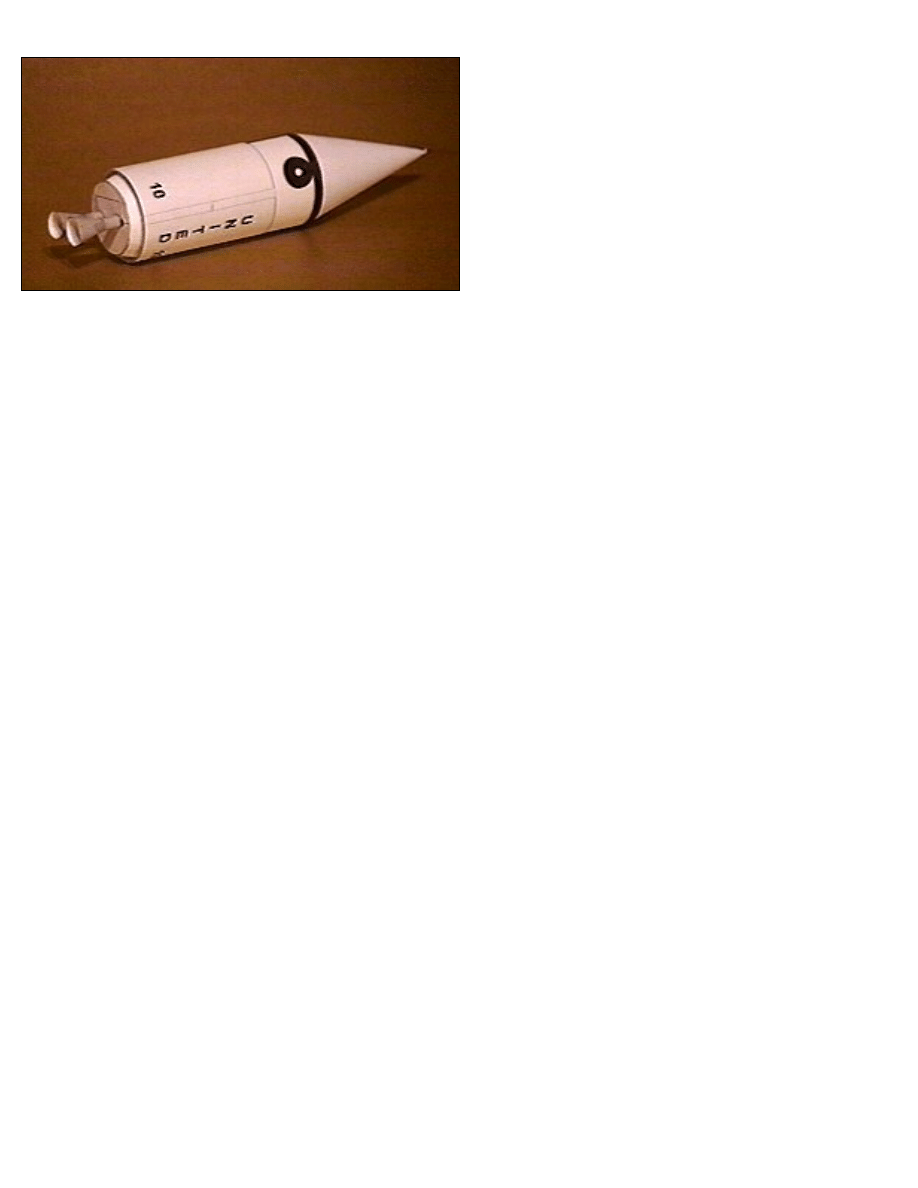
3. Cut out Atlas Forward LOX and Aft bulkheads (Page 2) and cement to a single layer of cardstock. When dry,
cut out Forward LOX Bulkhead, roll into cone shape, and glue. When dry, insert into top of Atlas body against
http://www76.pair.com/tjohnson/ac10ins.html (2 of 5)27-12-2003 19:22:40

Atlas Centaur 10 Paper Space Model
Atlas forward bulkhead mount. Trim or sand the bulkhead slightly to get a good fit, if necessary. Apply glue to
top of bulkhead once in place. Cut out Atlas Aft bulkhead and glue into place at base of stage against triangular
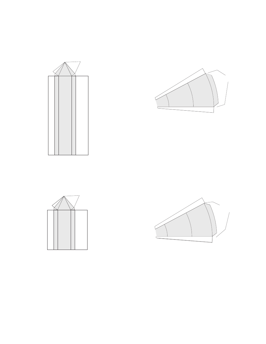
attach tabs, lining up engine fairing base with white engine fairing outlines on side of stage.
4. Cut out Atlas-Atlas Centaur Interstage Adapter (Page 2). Roll and cement to inside top of Atlas main tank body
tube, allowing half of adapter to extend from tube.
5. Cut out Atlas Centaur Interstage (Page 2). Roll and cement into a a double-layered cylinder as in Step 1. When
dry, attach to top of Atlas by carefully aligning tube seams and cementing to Atlas-Atlas Centaur Interstage
Adapter.
6. Cut out Atlas Centaur Interstage-Centaur Adapter (Page 2) and cement to card stock. When dry, roll and
cement to inside top of Interstage, allowing smaller portion to extend from tube.
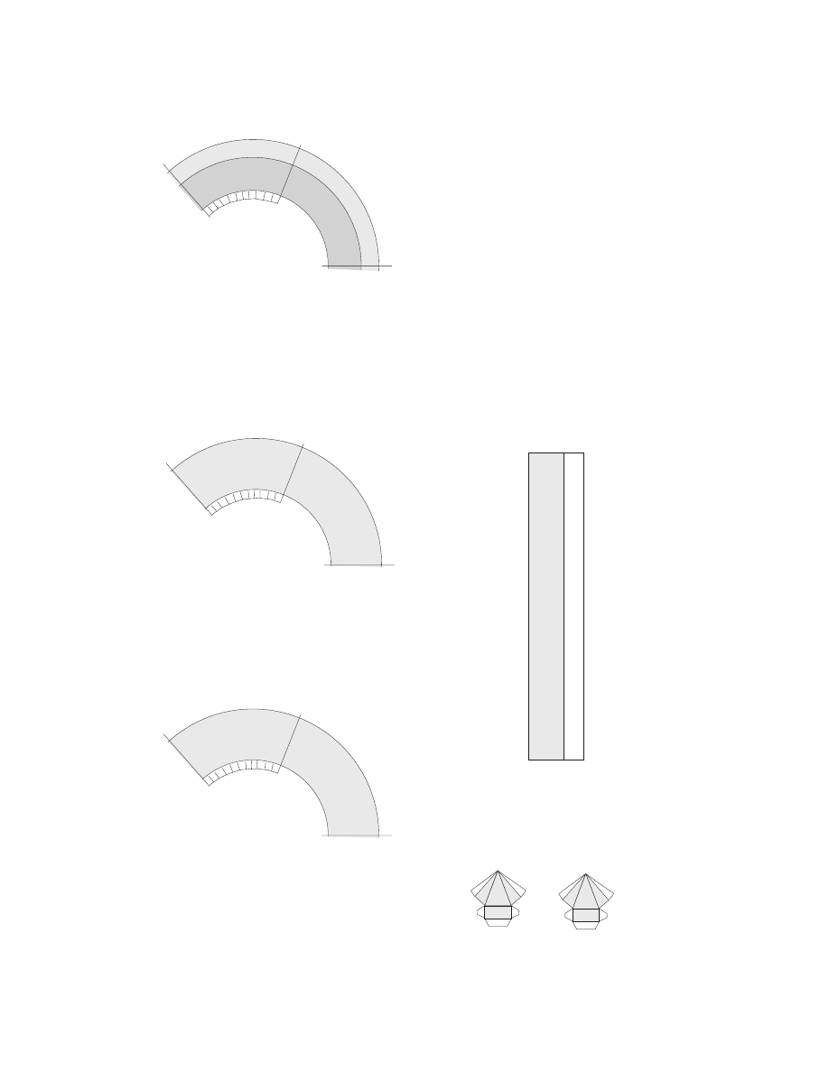
7. Cut out long and short instrumentation pods (page 3). Fold and cement/glue into long rectangular channels
topped by tapered triangulalar transition sections. Cement into place on opposite sides of Atlas main tank at
positions shown. Center the long pod on the Atlas body seam. The bottom of each pod should be at the top of the
"ribbed" booster skirt (second line from the missile base). Press the pods firmly against the side of the tank, then
press the tapered triangular transition section of each pod into place.
8. Cut out two booster skirt fairings (page 3). Fold in tabs on each side of fairing. Roll fairing slightly until it
assumes a tapered cylindrical shape. Test fit fairing by inserting its top, up to the top line on the fairing, into open
base of instrumentation pod and by aligning its base with the Aft Bulkhead. Carefully cement/glue both fairings
into place, being sure to center the fairing top and bottom.
9. Cut out LOX pipe (Page 4). Roll pipe into tight cylinder and cement. Cement LOX pipe to side of Atlas main
tank on black line, seam side inward. LOX pipe carried liquid oxygen around fuel tank from the upper LOX tank
during fueling on pad and in flight.
10. Cut out two vernier fairings (Page 4). Fold and glue into tapered triangular shape. Attach to opposite sides of
Atlas main tank just above booster fairing (second line up from base of missile). The small 1000 pound thrust, 45
degree angle vernier motors were mounted on these fairings.
11. Cut out Rocketdyne LR105-5 sustainer engine (page 4). Roll into truncated cone, underfolding inner layer so
"B" lines up with "A". Cement underfold end at bottom of thrust chamber. Cut upper adapter strips and fold
inward. Glue engine to center of aft bulkhead. The sustainer engine stayed attached to the Atlas body during the
flight.
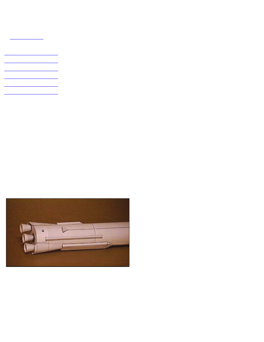
12. Cut out two Rocketdyne LR89-5 booster engines (page 4). Assemble using sustainer engine procedure. Attach
engines to outer positions of aft bulkhead. The booster engines and booster skirt fell away from Atlas after a little
more than two minutes of flight.
CENTAUR (SECOND STAGE) ASSEMBLY
http://www76.pair.com/tjohnson/ac10ins.html (3 of 5)27-12-2003 19:22:40
Atlas Centaur 10 Paper Space Model
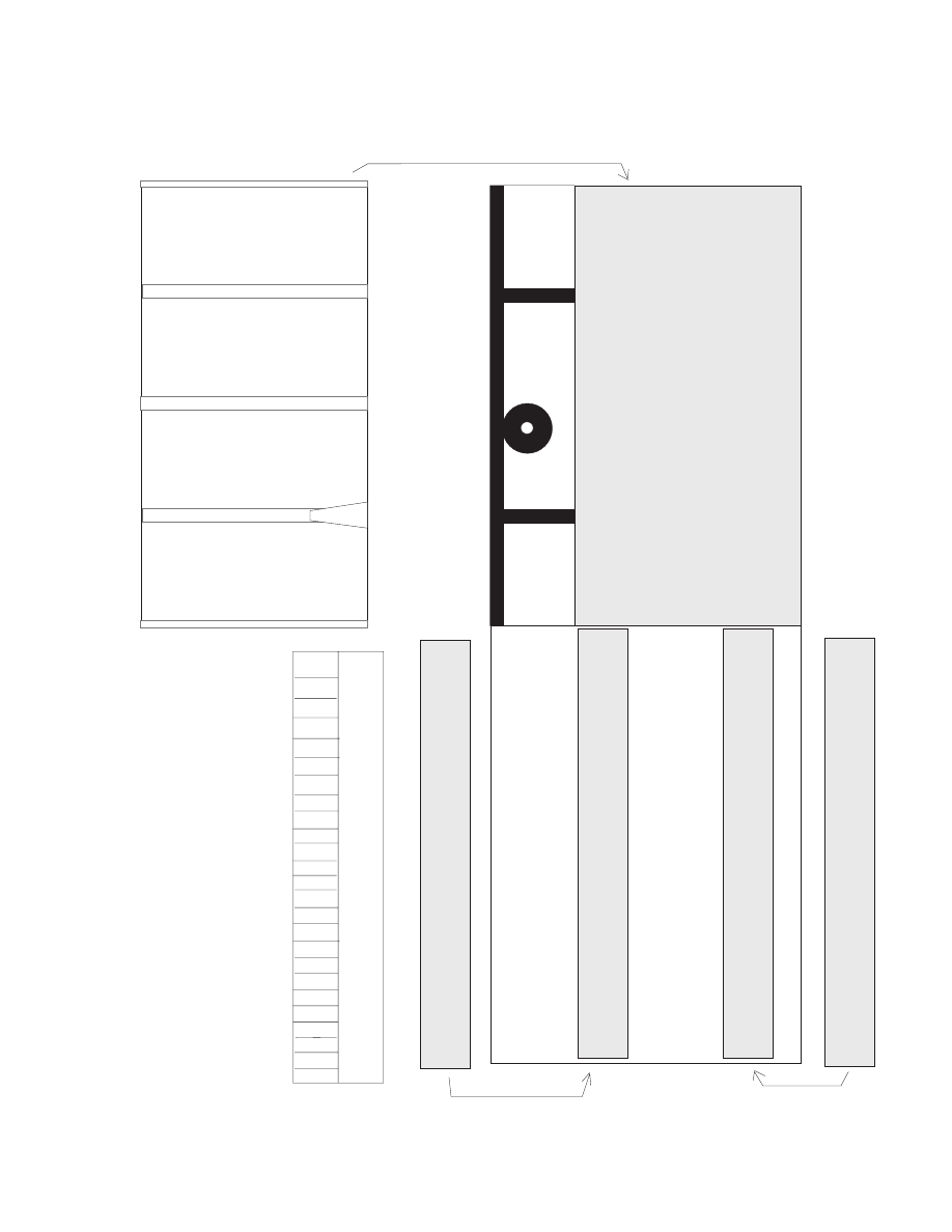
13. Cut out the Centaur Body and Centaur Forward and
Aft Bulkhead Mounts (Page 5). Trace bulkhead mount
outlines and attach as in Step 1.
14. Roll and cement Centaur Body into a double-layered cylinder as in Step 1.
15. Cut out Centaur LH2 Tank Forward Bulkhead, Centaur Thrust Structure Base, and Centaur Thrust Structure
(Page 6). Cement all three parts to card stock.
16. When dry, cut out LH2 Forward Bulkhead from card stock, roll into cone shape, and glue. When dry, insert
into top of Centaur body against Centaur Forward Bulkhead Mount. Trim or sand the bulkhead slightly to get a
good fit, if necessary. Apply glue to top of bulkhead once in place.
17. Cut out Centaur Thrust Structure from card stock, roll into truncated cone, and glue.
18. Cut out Centaur Thrust Structure Base Adapter (Page 6). Roll and insert into Centaur Thrust Structure so that
triangular attach tabs extend from bottom, smaller diameter end.
19. Cut out Centaur Thrust Structure Base from card stock. Align Base so that the Centaur Body seam lines up
with an imaginary line passing through the two RL-10 mounting points. Glue to attach tabs extending from
bottom of Centaur Thrust Structure.
20. When dry, insert Thrust Struture into base of Centaur body against Aft Bulkhead Mount. Trim or sand if
needed. Glue into place, leaving no excess glue. This will ensure a snug Centaur/Interstage press fit later.
21. Cut out Centaur-Fairing Adapter (Page 5). Cut upper portion into strips. Roll into Cylinder, insert into top of
Centaur Body allowing attachment strips to extend from top, and cement.
22. Cut out Payload Fairing Nose (Page 6). Roll into cone, then sparingly apply cement to underfold section at
seam and at base.
23. Attach Payload Fairing Nose to top of Centaur by applying cement to attach strips. Align Nose seam and roll
bars with Centaur seam and roll bars.
24. Cut out Centaur LH2 Tank Insulation Panels (Page 5). Wrap around grey part of Centaur body, aligning
seams, and cement in place.
http://www76.pair.com/tjohnson/ac10ins.html (4 of 5)27-12-2003 19:22:40

Atlas Centaur 10 Paper Space Model
25. Cut out RL-10 Nozzles and Thrust Chambers (Page 6). Roll Nozzles into cone and cement. Roll Thrust
Chambers into cylinders and cement. When dry, glue Thrust Chambers to top of Nozzles.
26. When dry, glue RL-10 engines to Centaur Thrust Structure Base on the black circles.
27. When Atlas and Centaur are both dry, test fit Centaur to top of Atlas Interstage. If necessary, trim interior
adapter slightly with scissors to allow for a tight fit. This is meant to be a friction fit.
Do not glue if you would like to be able to remove Centaur later.
28. Atlas Centaur 10 is ready to launch!
Last Update: January 9, 2003
http://www76.pair.com/tjohnson/ac10ins.html (5 of 5)27-12-2003 19:22:40
Atlas Centaur 10 (Surveyor 1) Page 1 of 6
Main Tank
Version 1.05
Copyright 2000
10
10
Forward
Bulkhead
Mount
Aft Bulkhead
Mount
Atlas Centaur 10 (Surveyor 1)
Page 2 of 6
Version 1.05
Copyright 2000
Atlas/Centaur
Interstage-Centaur
Adapter
(Mount to Cardstock)
Aft Atlas
Bulkhead
(mount to
cardstock)
Atlas/Centaur
Interstage
Atlas-Atlas/Centaur
Interstage Adapter
S
T
A
T
E
S
S
T
A
T
E
S
Atlas Forward LOX
Tank Bulkhead
(Cement to Card Stock)
Roll to Cone.
Underfold White
Section.
Cut
Atlas Centaur 10
(Surveyor 1)
Page 3 of 6
Booster Skirt Fairing
Booster Skirt Fairing
fold in here
fold in here
Long Instrumentation Pod
Fold on
lines
Short Instrumentation Pod
Version 1.05
Copyright 2000
LOX Pipe Top/Bottom
LOX Pipe
Vernier Fairings
Rocketdyne LR105-5 Sustainer Engine
(57,000 lb Thrust)
Two Rocketdyne LR89-5 Booster Engines
(165,000 lb Thrust Each)
Atlas Centaur 10
(Surveyor 1)
Page 4 of 6
A
B
A
B
Underfold B to A
A
B
Version 1.05
Copyright 2000
Atlas Centaur 10 (Surveyor 1)
Page 5 of 6
Version 1.05
Copyright 2000
Centaur Body
Centaur/Fairing
Adapter
Centaur LH2 Tank Insulation Panels
U
N
I
T
E
D
10
10
10
10
U
N
I
T
E
D
Fwd Bulkhead Mount
Aft Bulkhead Mount
Top
Top
Atlas Centaur 10 (Surveyor 1)
Page 6 of 6
Version 1.05
Copyright 2000
Payload Fairing Nose
Centaur Thrust Structure Base
(Mount to Card Stock)
Roll to Cone.
Underfold White
Sections.
Cut
Centaur LH2 Tank Fwd Bulkhead
(Mount to Card Stock)
RL-10 Thrust Chambers
RL-10 Nozzles
Centaur Thrust Structure
(Mount to Cardstock)
Centaur Thrust Structure
Base Adapter
Align with Body
Tube Seam
Document Outline
- Atlas Centaur 10 Paper Space Model.pdf
- pair.com
- ac10a.pdf
- ac10b.pdf
- ac10c.pdf
- ac10d.pdf
- ac10e.pdf
- ac10f.pdf
Wyszukiwarka
Podobne podstrony:
[Paper Model] [Space Craft] [Betexa 041] ATLANTIS Space Shuttle [1=72, jpg s]
Ch7 Model Space & Layouts
Ch07 Model Space & Layouts
Ch7 Model Space & Layouts
[Paper Model] [Warhammer 40k] Space Marine Whirlwind
[Paper Model] [Warhammer 40k] Space Marine Thunderhawk Gunship
[Paper Model] [Submarine] [Wilhelmshavner] U 96 Type VII C U Boat
[Airplane Paper model] (ModelArt # 00) (1 72) British Supermarine Spitfire MkIIA
(paper model)(mały modelarz 01 1959)polski parowóz pt 47 TXHIJ2ZLF4EVBIUZNK4BG4RLCURZMRTJCMLX3MI
[Paper Model] [Maly Modelarz 1963 11] Polish Mielec TS 11 Iskra Jet Trainer
[Paper Model] [German Mickey Mouse Club] [Airplane] 1982 Goofy's Hang Glider
Evolution in Brownian space a model for the origin of the bacterial flagellum N J Mtzke
[Paper Model] [Maly Modelarz 1990 07] Messerschmitt Me109
[Paper Model] [Building] [Morris] Eastbourne Signal Cabin
[Paper Model] [Pmodel] US Air Force F 86E
[Paper Model] [Auto] [YMjr] Expert Beer Truck
[Paper Model] Foldup paper Modeling
[Paper Model][Airplane][Fiddlers Green] Wright Glider of 1902 (1of2)
więcej podobnych podstron