Air-Conditioners For Building Application
INDOOR UNIT
PCFY- P
•
VKM-E
INSTALLATION MANUAL
For safe and correct use, read this manual and the outdoor unit installation manual thoroughly before installing
the air-conditioner unit.
INSTALLATIONSHANDBUCH
Aus Sicherheitsgründen und zur richtigen Anwendung vor Installation der Klimaanlage die vorliegende Bedie-
nungsanleitung und das Installationshandbuch gründlich durchlesen.
MANUEL D’INSTALLATION
Avant d’installer le climatiseur, lire attentivement ce manuel, ainsi que le manuel d’installation de l’appareil exté-
rieur pour une utilisation sûre et correct.
INSTALLATIEHANDLEIDING
Lees deze handleiding en de installatiehandleiding van het buitenapparaat zorgvuldig door voordat u met het
installeren van de airconditioner begint.
MANUALE DI INSTALLAZIONE
Per un uso sicuro e corretto, prima di installare il condizionatore d’aria leggere attentamente il presente manuale
ed il manuale d’installazione dell’unità esterna.
MANUAL DE INSTALACIÓN
Para un uso seguro y correcto, lea detalladamente este manual de instalación antes de montar la unidad de
aire acondicionado.
MANUAL DE INSTALAÇÃO
Para uma utilização segura e correcta, leia atentamente este manual e o manual de instalação da unidade exte-
rior antes de instalar o aparelho de ar condicionado.
PARA O INSTALADOR
PER L’INSTALLATORE
PARA EL INSTALADOR
VOOR DE INSTALLATEUR
POUR L’INSTALLATEUR
FÜR INSTALLATEURE
FOR INSTALLER
ΕΓΧΕΙΡΙΔΙΟ ΟΔΗΓΙΩΝ ΕΓΚΑΤΑΣΤΑΣΗΣ
Για σωστή και ασφαλή χρήση, διαβάστε προσεκτικά αυτό το εγχειρίδιο, καθώς και το εγχειρίδιο εγκατάστασης
της εξωτερικής μονάδας, πριν από την εγκατάσταση της μονάδας κλιματιστικού.
ΓΙΑ ΑΥΤΟΝ ΠΟΥ ΚΑΝΕΙ ΤΗΝ ΕΓΚΑΤΑΣΤΑΣΗ
MONTAJ ELK
İTABI
Emniyetli ve do
ğru kullanım için, klima cihazını monte etmeden önce bu kılavuzu ve dış ünite montaj kılavuzunu
tamamıyla okuyun.
MONTÖR
İÇİN
РУКОВОДСТВО ПО УСТАНОВКЕ
Для обеспечения безопасной и надлежащей эксплуатации внимательно прочтите данное руководство и
руководство по установке наружного прибора перед установкой кондиционера.
ДЛЯ УСТАНОВИТЕЛЯ
English
Deutsch
Français
Nederlands
Español
Italiano
Ελληνικά
Português
Türkçe
Русский
安装说明书
在安装空调机之前,请先通读此安装说明书,以便安全正确地使用。
安装人员适用
中文
01̲RG79D452H01̲EN.indd 1
01̲RG79D452H01̲EN.indd 1
2008/08/08 15:49:22
2008/08/08 15:49:22
2
H
W
D
1
2
3
4
5
6
7
► Before installing the unit, make sure you read all the “Safety precau-
tions”.
► Please report to your supply authority or obtain their consent before
connecting this equipment to the power supply system.
1. Safety precautions
3. Installing the indoor unit
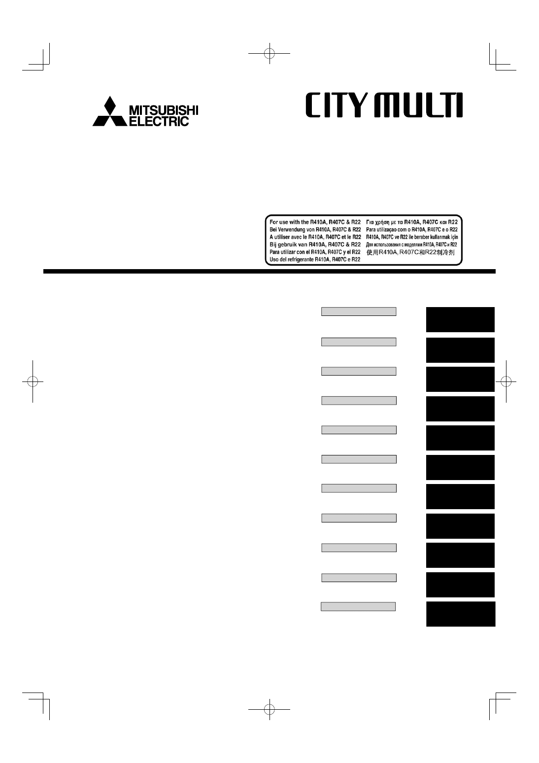
3.1. Check the indoor unit accessories (Fig. 3-1)
The indoor unit should be supplied with the following accessories
(contained in the inside of the intake grille).
Accessory name
Q’ty
1
Washer
4 pcs
2
Pipe cover
1 pc Large size (For gas tubing)
3
Pipe cover
1 pc Small size (For liquid tubing)
4
Band 4
pcs
5
Joint socket
1 pc Marked with “UNIT”
6
Socket cover
1 pc
7
Drain tubing cover
1 pc
Fig. 2-1
Contents
1. Safety precautions ........................................................................................ 2
2. Installation location ....................................................................................... 2
3. Installing the indoor unit................................................................................ 2
4. Installing the refrigerant piping .................................................................... 4
5. Drainage piping work .................................................................................... 5
6. Electrical work .............................................................................................. 5
7. Test run (Fig. 7-1) ......................................................................................... 7
Warning:
Describes precautions that must be observed to prevent danger of injury or
death to the user.
Caution:
Describes precautions that must be observed to prevent damage to the unit.
After installation work has been completed, explain the “Safety Precautions,” use,
and maintenance of the unit to the customer according to the information in the
Operation Manual and perform the test run to ensure normal operation. Both the
Installation Manual and Operation Manual must be given to the user for keeping.
These manuals must be passed on to subsequent users.
: Indicates an action that must be avoided.
: Indicates that important instructions must be followed.
: Indicates a part which must be grounded.
: Indicates that caution should be taken with rotating parts.
: Indicates that the main switch must be turned off before servicing.
: Beware of electric shock.
: Beware of hot surface.
ELV
: At servicing, please shut down the power supply for both the Indoor and
Outdoor Unit.
Warning:
Carefully read the labels affi xed to the main unit.
Warning:
• Ask the dealer or an authorized technician to install the air conditioner.
• Install the unit at a place that can withstand its weight.
• Use the specifi ed cables for wiring.
• Use only accessories authorized by Mitsubishi Electric and ask the dealer
or an authorized technician to install them.
• Do not touch the heat exchanger fi ns.
• Install the air conditioner according to this Installation Manual.
• Have all electric work done by a licensed electrician according to local
regulations.
• If the air conditioner is installed in a small room, measures must be taken
to prevent the refrigerant concentration from exceeding the safety limit
even if the refrigerant should leak.
• The cut face punched parts may cause injury by cut, etc. The installers are
requested to wear protective equipement such as gloves, etc.
Caution:
• Do not use the existing refrigerant piping, when use R410A or R407C refrigerant.
• Use ester oil, either oil or alkylbenzene (small amount) as the refrigerator oil
to coat fl ares and fl ange connections, when use R410A or R407C refrigerant.
• Do not use the air conditioner where food, pets, plants, precision instru-
ments, or artwork are kept.
• Do not use the air conditioner in special environments.
• Ground the unit.
• Install an leak circuit breaker, as required.
• Use power line cables of suffi cient current carrying capacity and rating.
• Use only a circuit breaker and fuse of the specifi ed capacity.
• Do not touch the switches with wet fi ngers.
• Do not touch the refrigerant pipes during and immediately after operation.
• Do not operate the air conditioner with the panels and guards removed.
• Do not turn off the power immediately after stopping operation.
2. Installation location
2.1. Outline dimensions (Indoor unit) (Fig. 2-1)
Select a proper position allowing the following clearances for installation and main-
tenance. (mm)
Models
W
D
H
A
B
C
E
P40
960
680
230
Min. 270 Min. 300 Min. 500 Max. 250
P63
1280
680
230
Min. 270 Min. 300 Min. 500 Max. 250
P100
1600
680
230
Min. 270 Min. 300 Min. 500 Max. 250
P125
1600
680
230
Min. 270 Min. 300 Min. 500 Max. 250
Warning:
Mount the indoor unit on a ceiling strong enough to withstand the weight of the unit.
2.2. Outline dimensions (Outdoor unit)
Refer to the outdoor unit installation manual.
Fig. 3-1
70+6
01̲RG79D452H01̲EN.indd 2
01̲RG79D452H01̲EN.indd 2
2008/08/08 15:49:51
2008/08/08 15:49:51
3
A
236
B
2
75
30
320
680
2
190
46
6
233
246
C
D
233
246
86 2
85
138
126
190
46
125
160
190
70
80
ø65
ø100
(mm)
/
5
3
5
3
4
2
2
0
10
–20
2
1
3
5
/
0
3. Installing the indoor unit
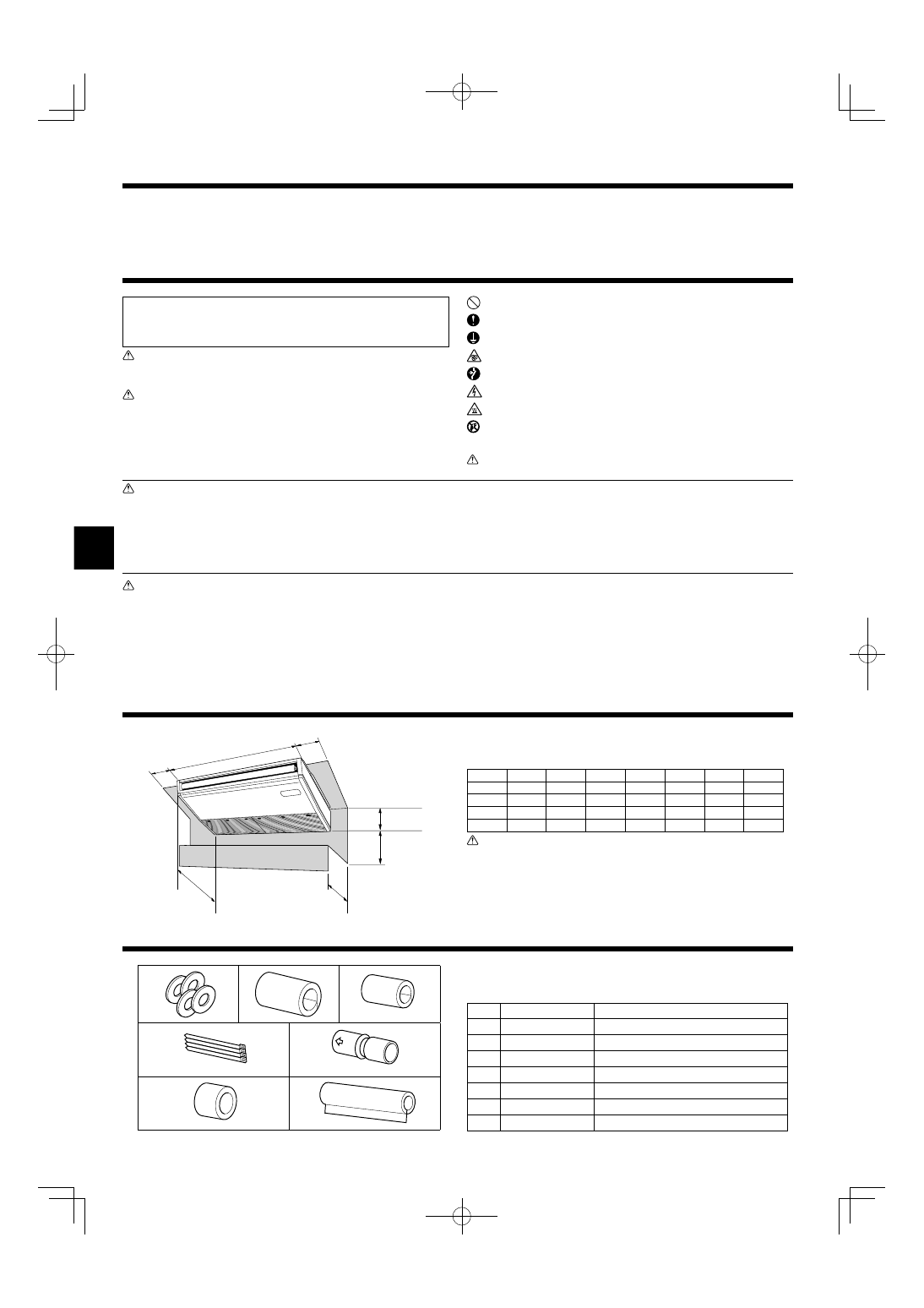
3.2. Preparation for installation (Fig. 3-2)
3.2.1. Suspension bolt installing spacing
(mm)
Models
A
B
P40
917
960
P63
1237
1280
P100,125 1557
1600
3.2.2. Refrigerant and drain tubing location
(mm)
Models
C
D
P40
184
203
P63
180
200
P100,125
180
194
A Front side outlet
F Left drain tubing
B Left side outlet
G Gas tubing
C Right side outlet
H Liquid tubing
D Independent piece (Removable)
I Rubber plug
E Right drain tubing
J with Joint socket 5
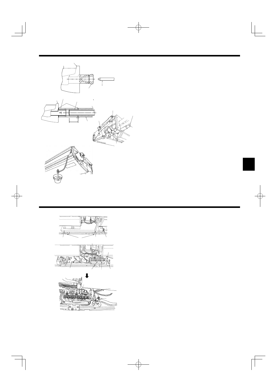
3.2.3. Selection of suspension bolts and tubing positions (Fig. 3-3)
Using the pattern paper provided for installation, select proper positions for suspen-
sion bolts and tubing and prepare relative holes.
A Pattern paper
B Suspension bolt hole
C Indoor unit width
Secure the suspension bolts or use angle stock braces or square timbers for bolt
installation.
D Use inserts of 100 kg to 150 kg each.
E Use suspension bolts of W3/8 or M10 in size.
3.2.4. Indoor unit preparation (Fig. 3-4)
1. Install the suspending bolts. (Procure the W3/8 or M10 bolts locally.)
Predetermine the length from the ceiling (1 within 100 mm).
A Ceiling surface B Suspending bolt C Suspending bracket
2. Remove the intake grille.
Slide the intake grille holding knobs (at 2 or 3 locations) backward to open the
intake grille.
3. Remove the side panel.
Remove the side panel holding screws (one in each side, right and left) then slide
the side panel forward for removal.
D Intake grille
J Slide the side panel forward.
E Intake grille holding knob
K Side panel
F Slide
L Remove the side panel holding screws.
G Hinge
M Remove the protective vinyl of vane.
H Pushing the hinge, pull out the intake grille.
2 Forcing open the intake grille or opening it to an angle of more than 120° may
damage the hinges.
3.3. Installing the indoor unit (Fig. 3-5)
Use a proper suspending method depending on the presence or absence of ceiling
materials as follows.
A In the presence of ceiling materials
c Ceiling
B In the absence of ceiling materials
d Suspending bolt
a Suspending bracket
e Washer 1
b Unit
f Washer (Local procurement)
g Double nuts
1) Directly suspending the unit
Installing procedures
1. Install the washer 1 (supplied with the unit) and the nuts (to be locally procured).
2. Set (hook) the unit through the suspending bolts.
3. Tighten the nuts.
Check the unit installing condition.
• Check that the unit is horizontal between the right and left sides.
• Check that the front and the rear of suspending brackets are horizontal.
(To keep drainage,the unit is inclined to the suspending brackets. The unit slopes
continuously downward from the front to the rear is the right installation position.)
Fig. 3-2
Fig. 3-3
Fig. 3-4
Fig. 3-5
01̲RG79D452H01̲EN.indd 3
01̲RG79D452H01̲EN.indd 3
2008/08/08 15:49:54
2008/08/08 15:49:54
4
7~12
90°
±0.5°
øA
R0.4~
R0.8
45°±2°
Fig. 3-6
3. Installing the indoor unit
Fig. 4-1
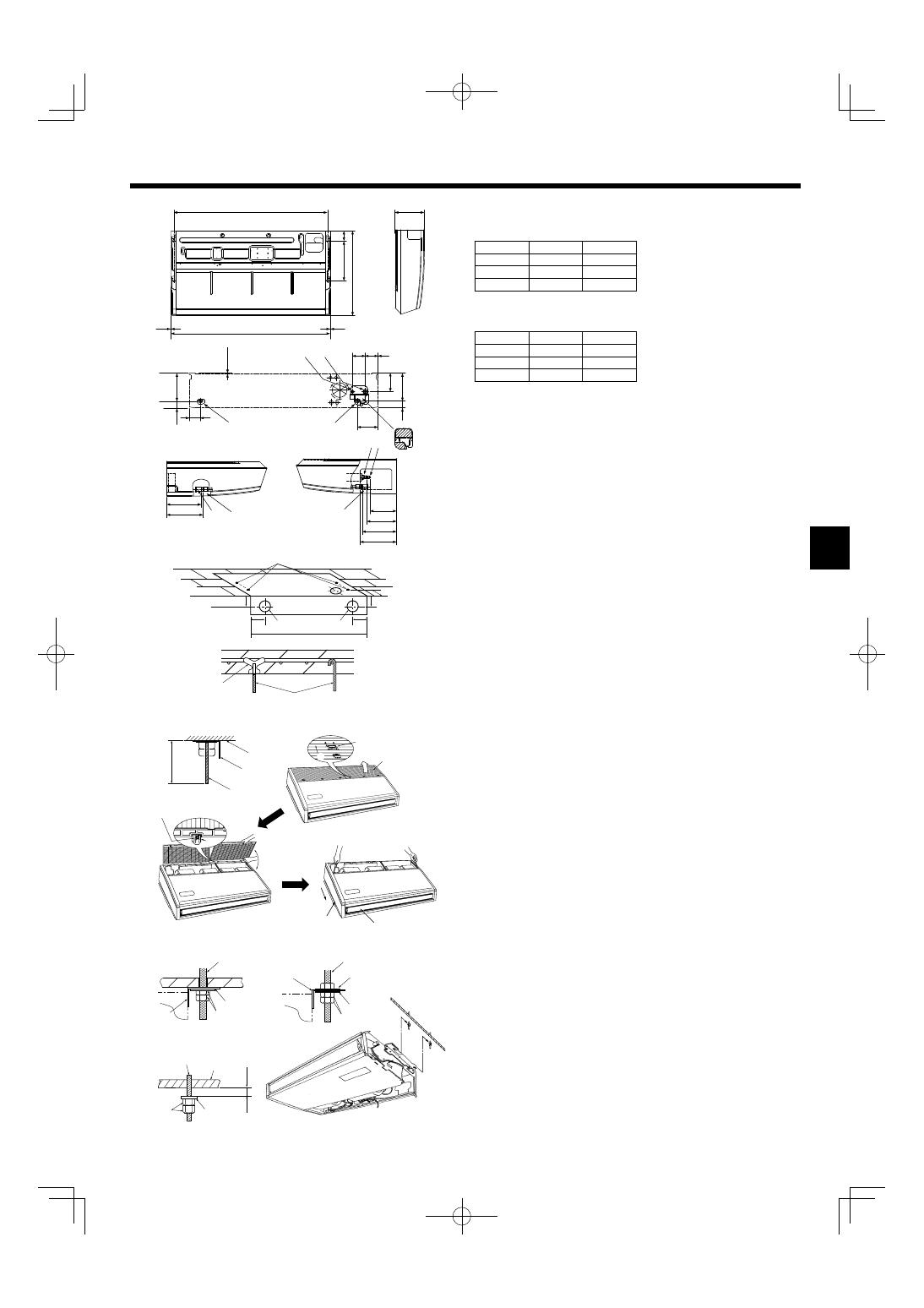
2) Installing the suspending bracket fi rst onto the ceiling (Fig. 3-6)
Installing procedures
1. Remove the suspending brackets and U-shaped washers from the unit.
2. Adjust the suspending bracket holding bolts on the unit.
3. Attach the suspending brackets to the suspending bolts.
4. Check that the suspending brackets are horizontal (front and rear / right and left).
5. Set (hook) the unit to the suspending brackets.
6. Tighten fi xed bolts of the suspending brackets.
w Be sure to install the U-shaped washers.
A Suspending bracket holding bolt
B Unit
C U-shaped washer
D Suspending bolt
E Washer 1
F Double nuts
4. Installing the refrigerant piping
4.1. Connecting pipes (Fig. 4-1)
• When commercially available copper pipes are used, wrap liquid and gas pipes
with commercially available insulation materials (heat-resistant to 100 °C or
more, thickness of 12 mm or more).
• The indoor parts of the drain pipe should be wrapped with polyethylene foam
insulation materials (specifi c gravity of 0.03, thickness of 9 mm or more).
• Apply thin layer of refrigerant oil to pipe and joint seating surface before tighten-
ing fl are nut.
• Use two wrenches to tighten piping connections.
• Use refrigerant piping insulation provided to insulate indoor unit connections.
Insulate carefully.
A Flare cutting dimensions
Copper pipe O.D.
(mm)
Flare dimensions
ø A dimensions (mm)
ø6.35
8.7 - 9.1
ø9.52
12.8 - 13.2
ø12.7
16.2 - 16.6
ø15.88
19.3 - 19.7
ø19.05
22.9 - 23.3
(mm)
G
P40
882 - 887
P63
1202 - 1207
P100, P125
1522 - 1527
B Refrigerant pipe sizes & Flare nut tightening torque
R407C or R22
R410A
Flare nut O.D.
Liquid pipe
Gas pipe
Liquid pipe
Gas pipe
Pipe size
(mm)
Tightening
torque
(N.m)
Pipe size
(mm)
Tightening
torque
(N.m)
Pipe size
(mm)
Tightening
torque
(N.m)
Pipe size
(mm)
Tightening
torque
(N.m)
Liquid pipe
(mm)
Gas pipe
(mm)
P40
ODø6.35 (1/4”)
14 - 18
ODø12.7 (1/2”)
49 - 61
ODø6.35 (1/4”)
14 - 18
ODø12.7 (1/2”)
49 - 61
17
26
P63
ODø9.52 (3/8”)
34 - 42
ODø15.88 (5/8”)
68 - 82
ODø9.52 (3/8”)
34 - 42
ODø15.88 (5/8”)
68 - 82
22
29
P100/125
ODø9.52 (3/8”)
34 - 42
ODø19.05 (3/4”)
68 - 82*
ODø9.52 (3/8”)
34 - 42
ODø15.88 (5/8”)
68 - 82
22
29
* Flare nut ø19.05 (purchased locally): Gas pipe of P100, P125 (R407C or R22).
C Apply refrigerating machine oil over the entire fl are seat surface.
4.2. Indoor unit (Fig. 4-2)
Installing procedures
1. Slide the supplied pipe cover 2 over the gas tubing until it is pressed against the
sheet metal inside the unit.
2. Slide the provided pipe cover 3 over the liquid tubing until it is pressed against
the sheet metal inside the unit.
3. Tighten the pipe covers 2 and 3 at the both ends (20 mm) with the supplied
bands 4.
A Gas tubing
E Pipe cover 3
B Liquid tubing
F Press the pipe cover against the sheet metal.
C Band 4
G Refrigerant tubing heat insulating material
D Pipe cover 2
Fig. 4-2
01̲RG79D452H01̲EN.indd 4
01̲RG79D452H01̲EN.indd 4
2008/08/08 15:49:56
2008/08/08 15:49:56
5
L
N
M1
M2
L
N
M1
M2
7
• For left side tubing, be sure to insert the rubber plug into the right drain port. (Fig.
5-1)
• Use VP-20 (O.D. ø26 (1”) PVC TUBE) for drain piping and provide 1/100 or more
downward slope.
• After completion of work, check that correct drain is available from the outfl ow
port of the drain tubing.
A Drain pan
B Plug
C Insert the driver etc.in the plug deeply.
Fig. 5-1
5. Drainage piping work
Installing procedures (Fig. 5-2)
1. Attach the joint socket 5 supplied with the unit to the drain port on the unit with a
vinyl chloride adhesive.
2. Fasten the socket cover 6 supplied with the unit to the joint socket 5.
3. Attach the fi eld drain tubing (VP-20) to the joint socket 5 with a vinyl chloride
adhesive.
4. Wrap the drain tubing cover 7 supplied with the unit. (Seam taping)
A Drain pan
B Drain tubing
C Socket cover 6
D Joint socket 5
E Drain tubing cover 7
F Stopper
G Instertion length 37mm
5. Check for correct drainage. (Fig. 5-3)
* Fill the drain pan with water of about 1 L from the air outlet.
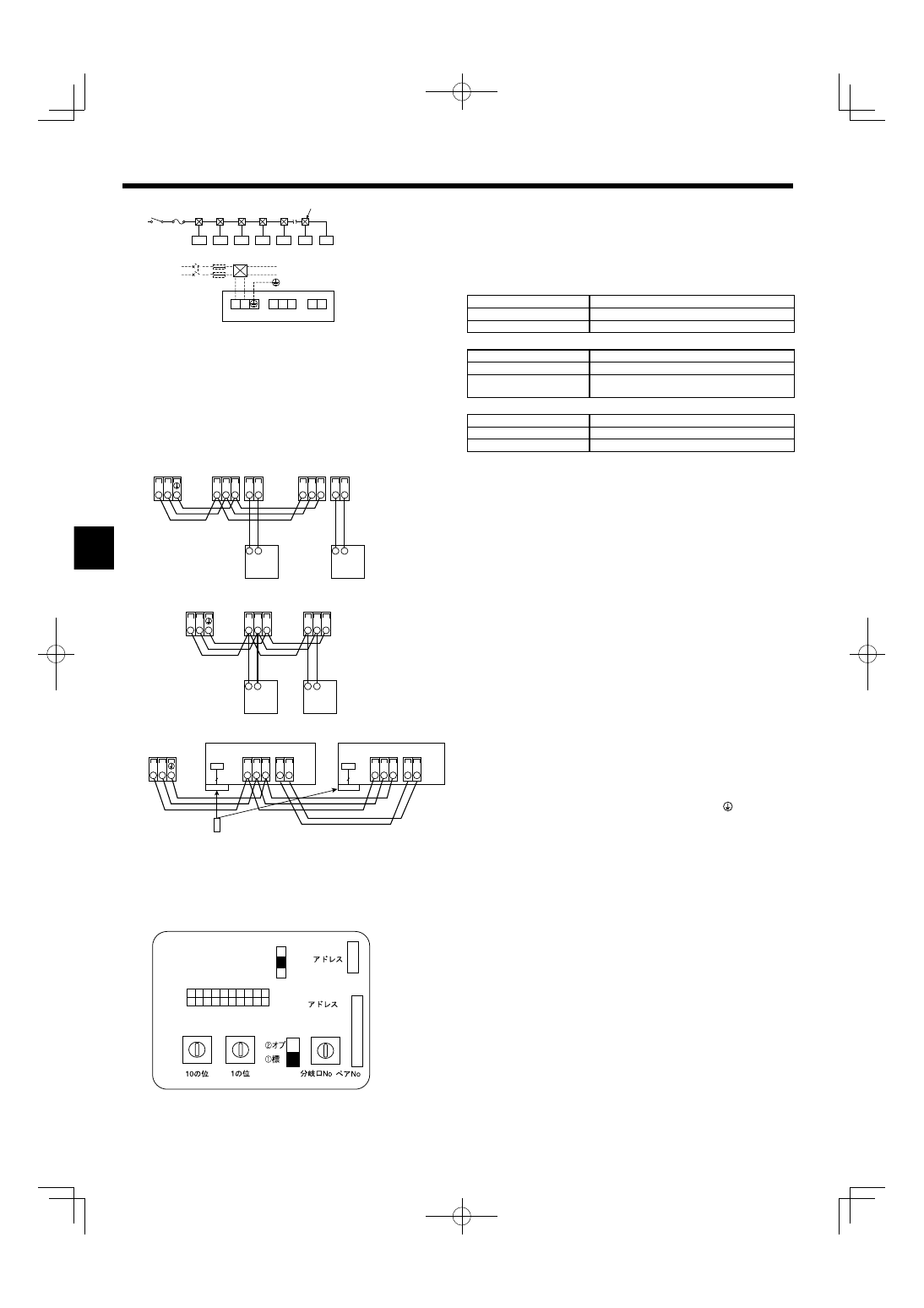
6. Electrical work
6.1. Electric wiring (Fig. 6-1)
Wiring procedures
1. Remove the tapping screw C then remove the beam.
2. Remove the (2) tapping screws B then remove the electric part cover A.
3. Connect the electric wires securely to the corresponding terminals.
4. Replace the removed parts.
5. Tie the electric wires with the local wiring clamp located in the right side of the
junction box.
A means for the disconnection of the supply with an isolation switch, or similar de-
vice, in all active conductors shall be incorporated in the fi xed wiring.
* Label each breaker according to purpose (heater, unit etc.)
A Cover
H Terminal block for transmission cable
B Set screws (2 pcs)
I Address board
C Set screws (Beam)
J Terminal block for MA Remote controller
D Wiring clamp
i Secure with the wiring clamp.
E Control board
F Wire service entrance
G Terminal block for power supply
6.2.Power supply wiring
• Install an earth line longer than other cables.
• Power supply codes of appliance shall not be lighter than design 60245 IEC 53
or 60227 IEC 53.
• A switch with at least 3 mm contact separation in each pole shall be provided by
the air conditioner installation.
Power cable size : more than 1.5mm² (3-core)
► Use earth leakage breaker (NV).
For breaker, means shall be provided to ensure disconnection of all active phase
conductors of the supply.
Fig. 5-2
Fig. 5-3
Fig. 6-1
01̲RG79D452H01̲EN.indd 5
01̲RG79D452H01̲EN.indd 5
2008/08/08 15:49:58
2008/08/08 15:49:58
6
SW14
SW11
SW12
1 2 3 4 5 6 7 8 9 10
ON
OFF
SW1
SWC
CN82
CN43
3
2
SWA
1
0 1
2
3
4
5
6
7
8
9
0 1
2
3
4
5
6
7
8
9
0 12
3
4
5
67
89
AB
C
D
EF
(10ths DIGIT)
(1s DIGIT)
. /
.
(BRANCH No.)
TB5
TB15 TB5
TB15
S
M1 M2
S
M1 M2
TB3
M1 M2
2
1
2
1
TB5
TB5
S
M1 M2
S
M1 M2
TB3
M1 M2
TB5
CN90
Pair No.
0
Pair No.
0
Pair No.
0
9
9
CN90
TB15
TB5
TB15
S
M1 M2
S
M1 M2
TB3
M1 M2
2
1
2
1
1 2
M1 M2 S
TB2
TB5
TB15
L N
6. Electrical work
Fig. 6-3
[Fig.6-2]
A Switch 16 A
D Total operating current be less than 16 A
B Overcurrent protection 16 A
E Pull box
C Indoor unit
6.3. Types of control cables
1. Wiring transmission cables
Types of transmission cable
Shielding wire CVVS or CPEVS
Cable diameter
More than 1.25 mm²
Length
Less than 200m
2. M-NET Remote control cables
Types of remote control cable Shielding wire MVVS
Cable diameter
0.5 to 1.25 mm²
Length
Add any portion in excess of 10m to within the
longest allowable transmission cable length 200m
3. MA Remote control cables
Types of remote control cable 2-core cable (unshielded)
Cable diameter
0.3 to 1.25 mm²
Length
Less than 200m
6.4. Connecting remote controller, indoor and out-
door transmission cables (Fig. 6-3)
• Connect indoor unit TB5 and outdoor unit TB3. (Non-polarized 2-wire)
The “S” on indoor unit TB5 is a shielding wire connection. For specifications
about the connecting cables, refer to the outdoor unit installation manual.
• Install a remote controller following the manual supplied with the remote control-
ler.
• Connect the remote controller’s transmission cable within 10 m using a 0.75 mm²
core cable. If the distance is more than 10 m, use a 1.25 mm² junction cable.
1 MA Remote controller
• Connect the “1” and “2” on indoor unit TB15 to a MA remote controller. (Non-
polarized 2-wire)
• DC 9 to 13 V between 1 and 2 (MA remote controller)
2 M-NET Remote controller
• Connect the “M1” and “M2” on indoor unit TB5 to a M-NET remote controller.
(Non-polarized 2-wire)
• DC 24 to 30 V between M1 and M2 (M-NET remote controller)
3 Wireless remote controller(When installing wireless signal receiver)
• Connect the wire of wireless signal receiver (9-pole cable) to CN90 of indoor con-
troller board.
• When more than two units are run under group control using wireless remote
controller, connect TB15 each with the same number.
• To chang Pair No. setting, refer to installation manual attached to wireless remote
controller. (In initial setting of indoor unit and wireless remote controller, Pair No.
is 0.)
A Terminal block for indoor transmission cable
B Terminal block for outdoor transmission cable(M1(A), M2(B),
(S))
C Remote controller
D wireless signal receiver
E wireless remote controller
6.5. Setting addresses (Fig. 6-4)
(Be sure to operate with the main power turned OFF.)
• There are 2 types of rotary switch setting available: setting addresses 1 to 9 and
over 10, and setting branch numbers.
1 How to set addresses
Example: If Address is “3”, remain SW12 (for over 10) at “0”, and match
SW11(for 1 to 9) with “3”.
2 How to set branch numbers SW14 (Series R2 only)
Match the indoor unit’s refrigerant pipe with the BC controller’s end connection
number.
Remain other than series R2 at “0”.
• The rotary switches are all set to “0” when shipped from the factory. These
switches can be used to set unit addresses and branch numbers at will.
• The determination of indoor unit addresses varies with the system at site. Set
them referring to the Data Book.
A Address board
Fig. 6-4
Fig. 6-2
01̲RG79D452H01̲EN.indd 6
01̲RG79D452H01̲EN.indd 6
2008/08/08 15:50:00
2008/08/08 15:50:00
7
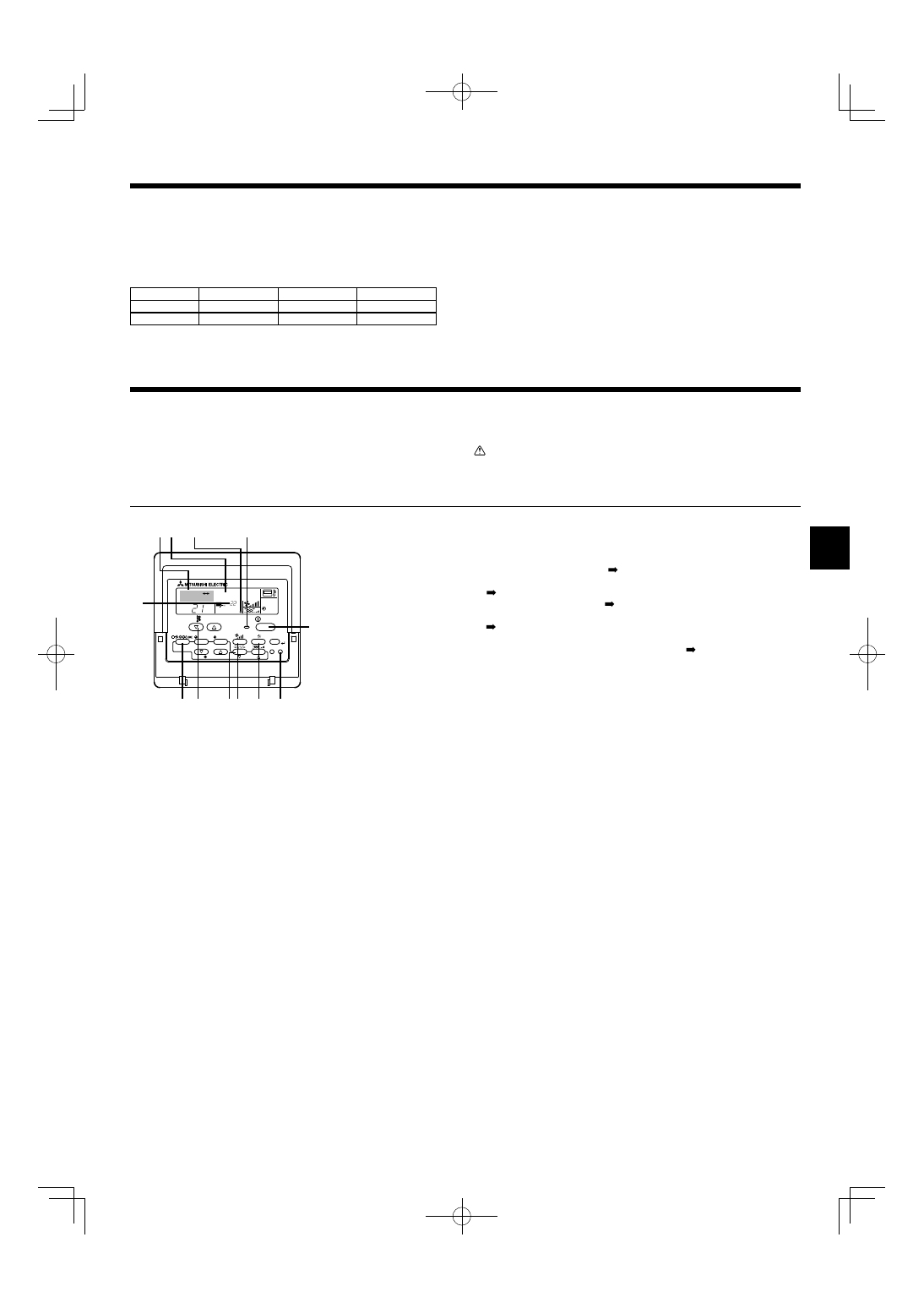
7. Test run (Fig. 7-1)
Fig. 7-1
°C
°C
SIMPLE
PAR-21MAA
ON/OFF
FILTER
CHECK
OPERATION
CLEAR
TEST
TEMP.
MENU
BACK
DAY
MONITOR/SET
CLOCK
ON/OFF
TEST RUN
COOL, HEAT
"!
A ON/OFF button
B Test run display
C Liquid pipe (Indoor unit)
temperature
display
D ON/OFF lamp
E Power display
F Error code display
Test run remaining time
display
G Set temperature button
H Mode selection button
I Air direction button
M TEST button
N Fan Speed button
O Louver button
► Do not carry out this test on the control wiring (low voltage circuit) termi-
nals.
Warning:
Do not use the air conditioner if the insulation resistance is less than 1.0 M
Ω.
7.1. Before test run
► After completing installation and the wiring and piping of the indoor and
outdoor units, check for refrigerant leakage, looseness in the power sup-
ply or control wiring, wrong polarity, and no disconnection of 1 phase in
the supply.
► Use a 500-volt megohmmeter to check that the resistance between the
power supply terminals and ground is at least 1.0 M
Ω.
7.2. Test run
Using wired remote controller (Fig. 7-1)
1 Turn on the power at least 12 hours before the test run.
2 Press the [TEST] button twice.
“TEST RUN” liquid crystal display
3 Press the [Mode selection] button and switch to the cooling (or heating) mode.
Make sure that cold (or warm) wind is blown out.
4 Press the [Fan speed] button.
Make sure that the wind speed is switched.
5 Press the [Air direction button] or [Louver button].
Check operation of the vane or louver.
6 Check operation of the outdoor unit fan.
7 Release test run by pressing the [ON/OFF] button.
Stop
8 Register a telephone number.
The telephone number of the repair shop, sales offi ce, etc., to contact if an error
occurs can be registered in the remote controller. The telephone number will be
displayed when an error occurs. For registration procedures, refer to the opera-
tion manual for the indoor unit.
Note:
• If an error code is displayed on the remote controller or if the air conditioner does not operate properly, refer to the outdoor unit installation manual or other
technical materials.
• The OFF timer is set for the test run to automatically stop after 2 hours.
• During the test run, the time remaining is shown in the time display.
• During the test run, the temperature of the indoor unit refrigerant pipes is shown in the room temperature display of the remote controller.
• When the VANE or LOUVER button is pressed, the message “NOT AVAILABLE” may appear on the remote controller display depending on the indoor unit
model, but this is not a malfunction.
6. Electrical work
6.7. Sensing room temperature with the built-in sensor
in a remote controller (Fig.6-4)
If you want to sense room temperature with the built-in sensor in a remote
controller, set SW1-1 on the control board to “ON”. The setting of SW1-7 and
SW1-8 as necessary also makes it possible to adjust the air fl ow at a time when
the heating thermometer is OFF.
6.6. Switch setting for different ceiling heights
(Fig.6-4)
With this unit, the air fl ow rate and fan speed can be adjusted by setting the SWA
(slide switch). Select a suitable setting from the table below according to the instal-
lation location.
* Make sure the SWA switch is set, otherwise problems such as not getting cool/
warm may occur.
SWA
3 (high ceiling)
2 (standard)
1 (silent)
P40, P63
3.5 m
2.7 m
2.5 m
P100, P125
4.2 m
3.0 m
2.6 m
SWA: Initial setting: 2 (Standard)
01̲RG79D452H01̲EN.indd 7
01̲RG79D452H01̲EN.indd 7
2008/08/08 15:50:01
2008/08/08 15:50:01
Please be sure to put the contact address/telephone number on
this manual before handing it to the customer.
HEAD OFFICE: TOKYO BLDG., 2-7-3, MARUNOUCHI, CHIYODA-KU, TOKYO 100-8310, JAPAN
Printed in Japan
RG79D452H01
This product is designed and intended for use in the residential,
commercial and light-industrial environment.
The product at hand is
based on the following
EU regulations:
• Low Voltage Directive 2006/95/ EC
• Electromagnetic Compatibility Directive
2004/108/EC
Authorized representative in EU: MITSUBISHI ELECTRIC EUROPE B.V.
HARMAN HOUSE, 1 GEORGE STREET, UXBRIDGE, MIDDLESEX UB8 1QQ, U.K.
01̲RG79D452H01̲EN.indd 8
01̲RG79D452H01̲EN.indd 8
2008/08/08 15:50:03
2008/08/08 15:50:03
Wyszukiwarka
Podobne podstrony:
IM PUHZ HRP71 100 125VHA2 YHA2 RG79D355H03 GB 01 2009
IM PEFY P15 63VMS1 L E KB79H130H03 GB 08 2009
IM PAC IF011B E IF012B E BH79D099H02 GB 09 2009
IM PEFY P40 250VMH E WT04198X02 GB 2005
IM MXZ 2A30 52VA SG79Y760H04 GB 04 2009
IM MSZ MUZ GE22 50VA JG79A103H07 GB 01 2010
IM MSH MS GE50VB E1 JG79A149H01 GB 02 2009
IM PAR21MAA WT05598X01 GB 04 2009
IM MSZ MUZ HC25 35VA SG79Y763H07 GB 01 2010
IM PAC SE51CRB WT03594X05 GB Aug 2009
IM MSC GE20 35VB E1 JG79A172H01 GB 02 2009
IM PCA RP50 140KA RG79D451H01 Jul 2009
IM PKFY P32 50VHM E RG79D439H03 Aug 2009
więcej podobnych podstron