Русский
INSTALLATION MANUAL
FOR INSTALLER
CONTENTS
1. THE FOLLOWING SHOULD ALWAYS BE OBSERVED FOR
SAFETY ........................................................................................... 2
2. INSTALLATION DIAGRAM & ACCESSORIES ................................ 2
3. SELECTING THE INSTALLATION LOCATION ................................ 3
4. OUTDOOR UNIT INSTALLATION ................................................... 4
5. INDOOR/OUTDOOR UNITS CONNECTION FINISHING AND
TEST RUN ....................................................................................... 5
English
Deutsch
Français
Nederlands
Español
Italiano
∂ÏÏËÓÈο
Português
Dansk
Svenska
Türkçe
SPLIT-TYPE AIR CONDITIONER
Model
MXZ-2A30VA
MXZ-2A40VA
MXZ-2A52VA
HFC
utilized
R410A
Refer to the installation manual of each indoor unit for indoor unit installation.
2
K
H
F
I
J
E
C
D
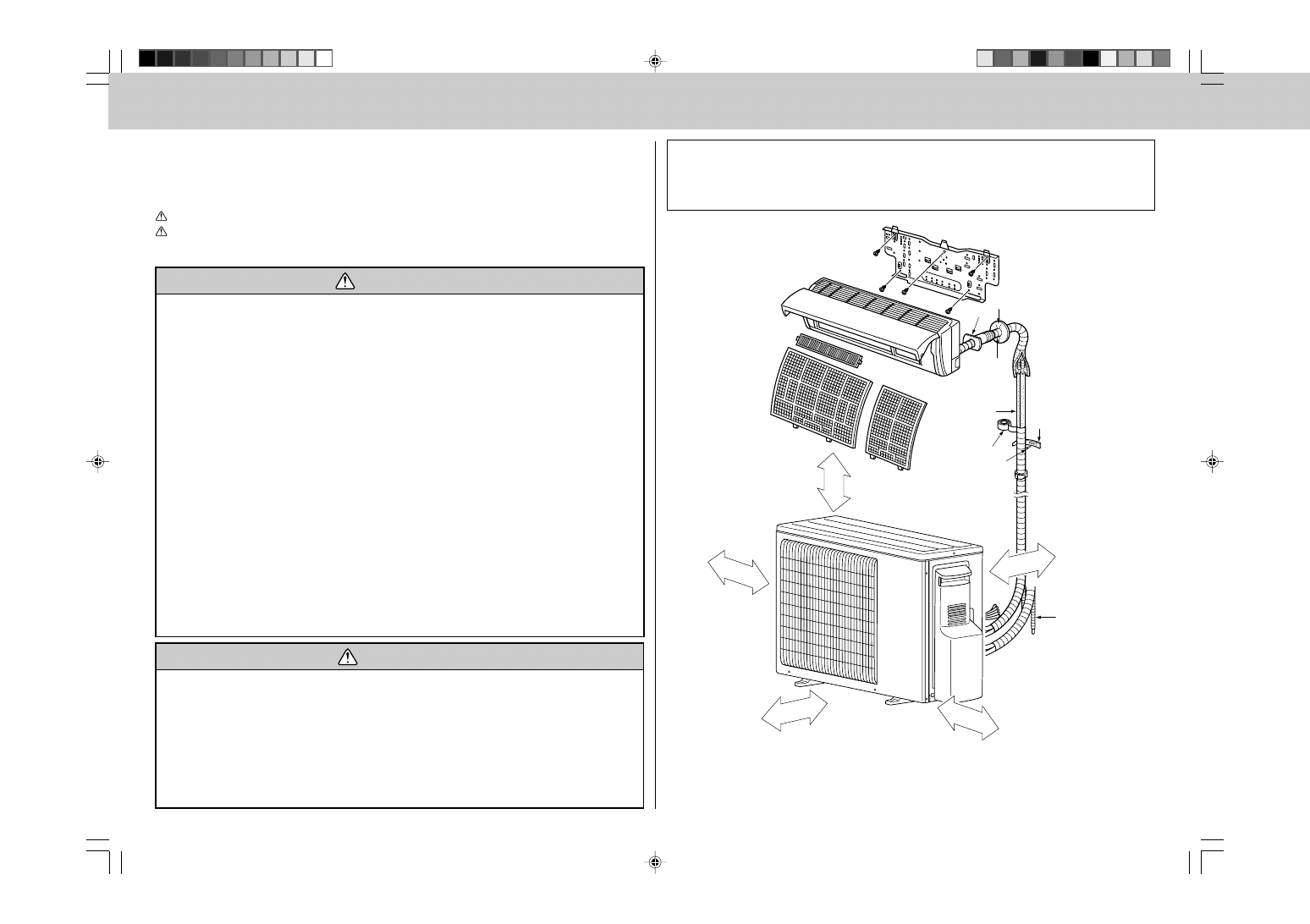
2. INSTALLATION DIAGRAM & ACCESSORIES
1. THE FOLLOWING SHOULD ALWAYS BE OBSERVED FOR
SAFETY
• Please provide an exclusive circuit for the air conditioner and make sure that no other electrical
appliances are connected to it.
• Be sure to read “THE FOLLOWING SHOULD ALWAYS BE OBSERVED FOR SAFETY” before install-
ing the air conditioner.
• Be sure to observe the cautions specified here as they include important items related to safety.
• The indications and meanings are as follows.
WARNING: Could lead to death, serious injury, etc.
CAUTION: Could lead to serious injury in particular environments when operated incorrectly.
• After reading this manual, be sure to keep it together with the OPERATING INSTRUCTIONS in a
handy place on the customer’s site.
WARNING
■ Do not install the unit by yourself (customer).
Incomplete installation could cause injury due to
fire, electric shock, the unit falling or leakage of
water. Consult the dealer from whom you pur-
chased the unit or special installer.
■ Install the unit securely in a place which can
bear the weight of the unit.
When installed in an insufficient strong place, the
unit could fall causing injury.
■ Use the specified wires to connect the indoor
and outdoor units securely and attach the
wires firmly to the terminal block connecting
sections so the stress of the wires is not ap-
plied to the sections.
Incomplete connecting and fixing could cause fire.
■ Do not use intermediate connection of the
power cord or the extension cord and do not
connect many devices to one AC outlet.
It could cause a fire or an electric shock due to de-
fective contact, defective insulation, exceeding the
permissible current, etc.
■ Check that the refrigerant gas due not leak
after installation has completed.
If refrigerant gas leaks indoors, and comes into
contact with the fire of a fan heater, space heater,
stove, etc., harmful substances will be generated.
■ Perform the installation securely referring to
the installation manual.
Incomplete installation could cause a personal
injury due to fire, electric shock, the unit falling or
leakage of water.
■ Perform electrical work according to the in-
stallation manual and be sure to use an ex-
clusive circuit.
If the capacity of the power circuit is insufficient
or there is insufficient electrical work, it could re-
sult in a fire or an electric shock.
■ Attach the electrical cover to the indoor unit and
the service panel to the outdoor unit securely.
If the electrical cover in the indoor unit and/or the
service panel in the outdoor unit are not attached
securely, it could result in a fire or an electric
shock due to dust water, etc.
■ Be sure to use the part provided or specified
parts for the installation work.
The use of defective parts could cause an injury
due to a fire, an electric shock, the unit falling,
leakage of water, etc.
■ Be sure to cut off the main power in case of
setting up the indoor electronic control P.C.
board or wiring works.
It could cause an electric shock.
■ The appliance shall be installed in accordance
with national wiring regulations.
■ When installing or relocating the unit, make
sure that no substance other than the speci-
fied refrigerant (R410A) enters the refrigerant
circuit.
Any presence of foreign substance such as air
can cause abnormal pressure rise or an explo-
sion.
More than 100 mm
Open as a rule
More than 500 mm
if the front and both
sides are open
More than 100 mm
More than 200 mm if
there are obstacles to
both sides
Open as a rule
More than 500 mm if
the back, both sides
and top are open
More than 350 mm
Note:
The dimensions given along the arrows above are required to guarantee
the air conditioner’s performance. Install the unit in as wide a place as
possible for later service or repairs.
Before installation
This installation manual is only for the outdoor unit installation. In installing the indoor units, refer to the
installation manual attached to each indoor unit.
Any structural alternations necessary for the installation must comply with the local building code require-
ments.
CAUTION
■ Perform earthing.
Do not connect the earth wire to a gas pipe, water
pipe, lightning rod or telephone earth wire. Defec-
tive earthing could cause an electric shock.
■ Do not install the unit in a place where an in-
flammable gas leaks.
If gas leak and accumulate in the area surround-
ing the unit, it could cause an explosion.
■ Fasten a flare nut with a torque wrench as
specified in this manual.
When fastened too tight, a flare nut may broken after
a long period and cause a leakage of refrigerant.
■ Install an earth leakage breaker depending
on the installation place (Where it is humid).
If a earth leakage breaker is not installed, it could
cause an electric shock.
■ Perform the drainage/piping work securely
according to the installation manual.
If there is a defect in the drainage/piping work,
water could drop from the unit and household
goods could be wet and damaged.
3
ACCESSORIES
Check the following parts before installation.
<Outdoor unit>
1
Drain socket
1
Parts to be locally procured
A
Power supply cord
1
(3-core 2.5 mm
2
)
B
Indoor/outdoor unit connecting wire
1
(4-core 1.0 mm
2
/1.5 mm
2
)
C
Extension pipe According to “Selecting pipe size”
1
D
Wall hole cover
1
E
Piping tape
1
F
Extension drain hose (or soft vinyl chloride hose of
1
15 mm in internal diameter or hard vinyl chloride pipe VP16)
G
Refrigeration oil
Little amount
H
Putty
1
I
Pipe fixing band
2 to 7
(The number depends on the pipe length.)
J
Fixing screw for I
2 to 7
(The number depends on the pipe length.)
K
Wall hole sleeve
1
L
Soft vinyl chloride hose of 15 mm in internal diameter
1
or hard vinyl chloride pipe VP16 for drain socket
NOTE:
• Do not use the drain socket and the drain cap in the cold region.
Drain may freeze and it makes the fan stop.
• The “Q’ty” for B to K in the above table is the quantity to be used per indoor unit.
WARNING:
Be sure to use specified accessories and supplied parts for installation work. If there is some defi-
ciency in parts, it may cause a risk of fire, electric shock, injury by a unit fall or water leakage.
3. SELECTING THE INSTALLATION LOCATION
• Where it is not exposed to strong wind.
• Where airflow is good and dustless.
• Where it is not exposed to rain and direct sunshine.
• Where neighbours are not annoyed by operation sound or hot air.
• Where rigid wall or support is available to prevent the increase of operation sound or vibration.
• Where there is no risk of combustible gas leakage.
• When installing the unit at a high level, be sure to fix the unit legs.
• Where it is at least 3 m away from the antenna of TV set or radio. Operation of the air conditioner may
interfere with radio or TV reception in areas where reception is weak. An amplifier may be required for the
affected device.
• Install the unit horizontally.
• Please install it in an area not affected by snowfall or blowing snow. In areas with heavy snow, please install
a canopy, a pedestal and/or some baffle boards.
Note:
It is advisable to make a piping loop near outdoor unit so as to reduce vibration transmitted from there.
WARNING:
Be sure to install the unit in a place that well sustains its weight.
Installing in a place with less strength may result in a unit falling, causing a risk of injury.
CAUTION:
Avoid the following places for installation where air conditioner trouble is liable to occur.
• Where flammable gas could leak.
• Where there is much machine oil.
• Salty places such as the seaside.
• Where sulfide gas is generated such as
a hot spring.
• Where there is high-frequency or wire-
less equipment.
Note:
When operating the air conditioner in low outside temperature, be sure to follow the instructions de-
scribed below.
• Never install the outdoor unit in a place where its air inlet/outlet side may be exposed directly to
wind.
• To prevent exposure to wind, install the outdoor unit with its air inlet side facing the wall.
• To prevent exposure to wind, it is recommended to install a baffle board on the air outlet side of the
outdoor unit.
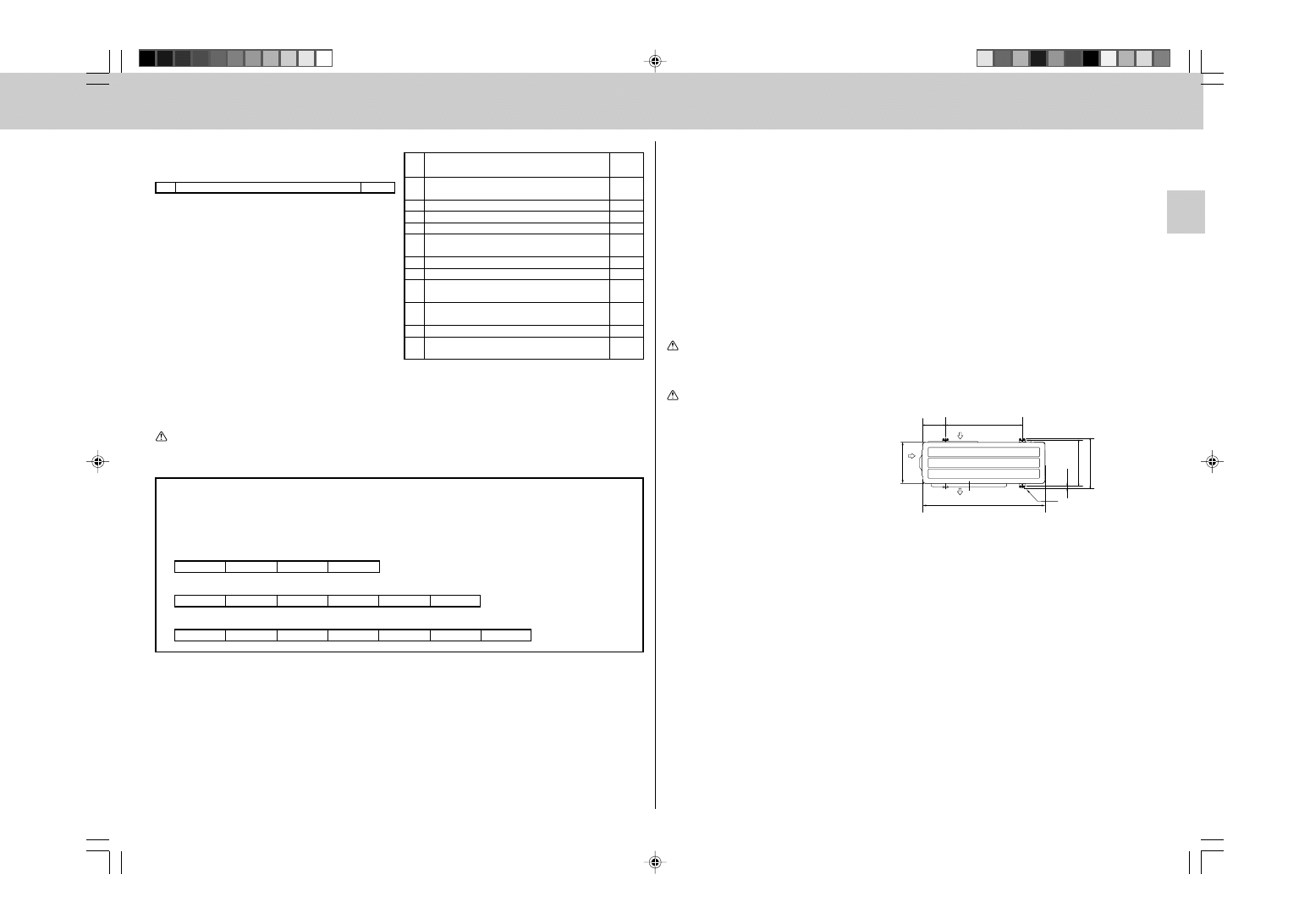
Constraints On Indoor Unit Installation
You should note that indoor unit that can be connected to this outdoor unit have the following constraints on
them.
• Indoor units with model numbers 22, 25 and 35 can be connected. Refer to the table below for possible
indoor unit combinations.
304~325
344.5
17.5
500
150
800
285
Air in
Air out
Air in
4-10
× 21 Oval holes
(Unit: mm)
MXZ-2A30VA Combination
2 UNIT
22+22
22+25
25+25
MXZ-2A40VA Combination
2 UNIT
22+22
22+25
22+35
25+25
25+35
MXZ-2A52VA Combination
2 UNIT
22+22
22+25
22+35
25+25
25+35
35+35
4
}
}
4. OUTDOOR UNIT INSTALLATION
4-1
INSTALLING THE UNIT
• Be sure to fix the unit’s legs with bolts when installing it.
• Be sure to install the unit firmly to ensure that it does not fall by an earthquake or a gust.
• Refer to the figure in the right for concrete foundation.
4-2
MOUNTING ARRANGEMENT OF DRAIN SOCKET
Please perform the drain piping work only when draining from one place.
CAUTION:
Do not use drain socket and drain cap in the cold region.
Drain may freeze and it makes the fan stop.
1 Please choose one hole to discharge drain and install the drain socket to the hole.
2 Please close the rest of the holes with the drain caps.
3 Please connect a vinyl hose of 15 mm in the inside diameter on the market with the drain socket and lead drain.
4-3
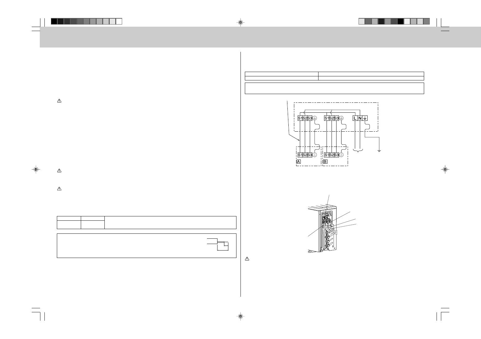
INDOOR/OUTDOOR WIRE CONNECTION AND OUTDOOR POWER
SUPPLY CORD CONNECTION
• Be sure to lead in the power supply cord A to the air conditioner in accordance with the specification table
below and “Technical Standards for Electrical Installation”.
• Be sure to use special circuits for room air conditioner.
CAUTION:
Attach an earth leakage breaker according to your installation location. If any breaker is not attached, it
may cause a risk of electric shock.
WARNING:
Be sure to comply with “Technical Standards for Electrical Installation”, follow this manual and use
special circuits for electrical work. If there is a lack of circuit capacity or some deficiency in installation,
it may cause a risk of fire or electric shock.
Overcurrent that might be produced may include DC substances. Be careful to choose the correct type
of overcurrent protection switch.
Rated Voltage
Breaker capacity
230 V
2A30:10 A
2A40/2A52:15 A
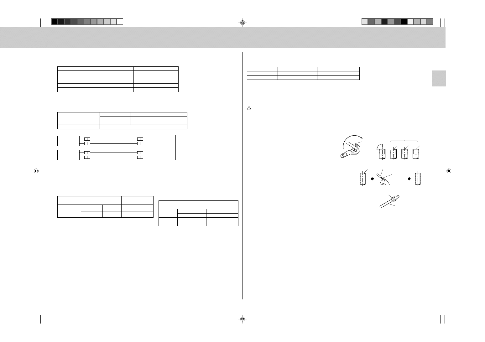
• Peel off both ends of the cables as shown in the right.
• Take care not to let the cables contact the pipes inside the unit.
• Take enough care to connect the indoor/outdoor unit connecting wire correctly be-
tween the respective indoor units and the outdoor unit.
• Make earth wire a little longer than the others. (more than 35 mm)
Connect to the supply terminals and leave a contact separation of at least 3 mm at each pole to
disconnect the source power pole. (When the power switch is shut off, it must disconnect all poles.)
1 Remove the service panel.
2 Remove fixing screw of terminal cover.
3 Connect the indoor/outdoor wire and power supply cable to the terminal block.
4 Replace the terminal cover securely.
WARNING:
• Be sure to attach the service panel of the outdoor unit securely, otherwise it may result in a fire or an
electric shock from dust or water.
• Use the indoor/outdoor unit connecting wire that meets the Standards to connect the indoor and
outdoor units and fix the wire to the terminal block securely so that no external force is conveyed to
the connecting section of the terminal block. Incomplete connection or fixing of the wire could result
in a fire.
• Be sure to attach the terminal block cover on the both indoor and outdoor units. If the terminal block
cover is incorrectly attached, it may cause a risk of fire or electric shock due to dust or water pen-
etration.
Cable clamp
Route the indoor/outdoor unit connecting wire B and
the power supply cord A along with the unit.
Power supply cord A
ı unit
Å unit
Be sure that the indoor/outdoor unit
connecting wire B does not contact
the stop valve.
• For the power supply cord and the indoor/outdoor unit connecting wires, be sure to use the ones in compli-
ance with the standards.
• Be sure to push the core until it is hidden and pull each cable to make sure that it is not pulled up. Incomplete
insertion may cause a risk of burning the terminal blocks.
Power supply cord Specification
Cable 3-core 2.5 mm
2
, in conformity with Design 60245 IEC 57.
Indoor and Outdoor connecting wire Specification
Cable 4-core 1.0/1.5 mm
2
, in conformity with Design 60245 IEC 57.
This installation manual is only for the outdoor unit installation. In installing the indoor units, refer to the
installation manual attached to each indoor unit.
35 mm
15 mm
Indoor/outdoor unit connecting wire
<OUTDOOR UNIT>
POWER SUPPLY
~/N 230 V 50 Hz
UNIT
UNIT
Firmly tighten the indoor/outdoor unit connecting
wire B and the power supply cord A.
5
5. INDOOR/OUTDOOR UNITS CONNECTION FINISHING AND TEST RUN
Model
Pipe size for indoor unit
Allowable
name
connection pipe size
22
Liquid pipe
ø6.35 mm
ø6.35 mm
25
35
Gas pipe
ø9.52 mm
ø9.52 mm
5-1
FLARED CONNECTIONS
PIPE LENGTH AND HEIGHT DIFFERENCE
Limits
2A30VA
2A40VA
2A52VA
Pipe length per indoor unit
15 m
max.
20 m
max.
20 m
max.
Total pipe length for multi-system
20 m
max.
30 m
max.
30 m
max.
Height difference
10 m
max.
*15 m
max.
*15 m
max.
No. of bends per indoor unit
15
max.
20
max.
20
max.
Total No. of bends for multi-system
20
max.
30
max.
30
max.
* If the outdoor unit is installed higher than the indoor unit, max. height difference is reduced to 10 m.
Refrigerant adjustment ....... If pipe length exceeds 20 m, additional refrigerant (R410A) charge is required.
(The outdoor unit is charged with refrigerant for total pipe length up to 20 m.)
Pipe length
Up to 20 m
No additional charge is required.
Exceeding 20 m
Additional charge is required.
(Refer to the table below.)
Refrigerant to be added
20 g/m
× (refrigerant piping length(m)-20)
• For pipe size, see the table below.
SELECTING PIPE SIZE
The diameter of connection pipes differs according to the type and capacity of indoor units. Match the diameters
of connection pipes for indoor and outdoor units according to the following table.
MXZ-2A30VA
MXZ-2A40VA
MXZ-2A52VA
Valve size for outdoor unit
Å UNIT
Liquid pipe
ø6.35 mm
Gas pipe
ø9.52 mm
ı UNIT
Liquid pipe
ø6.35 mm
Gas pipe
ø9.52 mm
Copper
pipe
Good
No good
Tilted Uneven Burred
Burr
Copper pipe
Spare
reamer
Pipe cutter
Flare nut
Copper pipe
5-2
FLARING WORK
• Main cause of gas leakage is defect in flaring work.
Perform flaring work correctly in the following procedure.
1. Pipe cutting
• Cut the copper pipe correctly with pipe cutter.
2. Burrs removal
• Completely remove all burrs from the cut cross
section of the pipe.
• Put the end of the copper pipe downward to pre-
vent burrs from dropping in the pipe.
3. Putting nut on
• Remove flare nuts attached to indoor and outdoor
units, then put them on pipe having completed
burr removal.
(not possible to put them on after flaring work)
• Flare nut for R410A pipe may differ from R22 pipe
depending on the diameter of pipe.
PIPING PREPARATION
1 If you use commercially available copper pipes, use the following table for pipe specifications.
Outside diameter
Wall thickness
Liquid pipe
ø6.35 mm
0.8 mm
Gas pipe
ø9.52 mm
0.8 mm
2 For insulation material, use 8 mm-thick heat-insulating expended polyethylene with a specific gravity of
0.045.
3 Ensure that the 2 refrigerant pipes are insulated to prevent condensation.
4 Refrigerant pipe bending radius must be 100 mm or more.
CAUTION:
Be sure to use the insulation of specified thickness. Excessive thickness may cause incorrect installa-
tion of the indoor unit and lack of thickness may cause dew drippage.
90
°
Outdoor
unit
Indoor unit
ı UNIT
Indoor unit
Å UNIT
6
A
Die
Copper pipe
Flare nut
Die
Copper pipe
Smooth all around
Even length
all around
Inside is shining without any scratches
York
4. Flaring work
• Perform flaring work using flaring tool as shown in the right.
A (mm)
Outside diameter Flare tool for R410A
Conventional flare tool
clutch type
Clutch type
Wing nut type
ø6.35 mm
0 to 0.5
1.0 to 1.5
1.5 to 2.0
ø9.52 mm
0 to 0.5
1.0 to 1.5
1.5 to 2.0
Firmly hold copper pipe in a die in the dimension shown in
the table above.
5. Check
• Compare the flared work with the figure below.
• If flare is noted to be defective, cut off the flared section
and perform flaring work again.
5-3
PIPE CONNECTION
Note:
Fasten a flare nut with a torque wrench as specified in the table below.
When fastened too tight, a flare nut may be broken after a long period and cause a leakage of refriger-
ant.
1. Indoor unit connection
• Connect both liquid pipe and gas pipe to indoor unit.
- Apply a thin coat of refrigeration oil to the seat surface of pipe.
- For connection, align the center of both pipe and union, then tighten the first 3 to 4 turns in flare nut by
hand.
- For tightening the union part of the indoor unit side, use the table below as a standard and tighten
the flare nut with two wrenches. Excessive tightening damages the flared section.
Pipe diameter
Tightening torque
N·m
kgf·cm
ø6.35 mm
13.7 to 17.7
140 to 180
ø9.52 mm
34.3 to 41.2
350 to 420
2. Outdoor unit connection
• Connect pipes to the pipe joint part of the stop valve in the same method as the indoor unit.
- For tightening, use the same tightening torque applied for indoor unit and tighten the flare nut with
torque wrench or spanner.
INSULATION AND TAPING
1 Cover piping joints with pipe cover.
2 For outdoor unit side, surely insulate every piping including valves.
3 Using piping tape E, apply taping starting from the entry of outdoor unit.
• Fix the end of piping tape E with adhesive tape.
• When piping has to be arranged through above ceiling, closet or area where the temperature and humidity
are high, wind additional commercially sold insulation for prevention of condensation.
5-4
PURGING PROCEDURES • LEAK TEST
• Perform the manifold valve work securely according to the installation manual of the manifold valve.
Flaring tool
Wing nut type
Clutch type
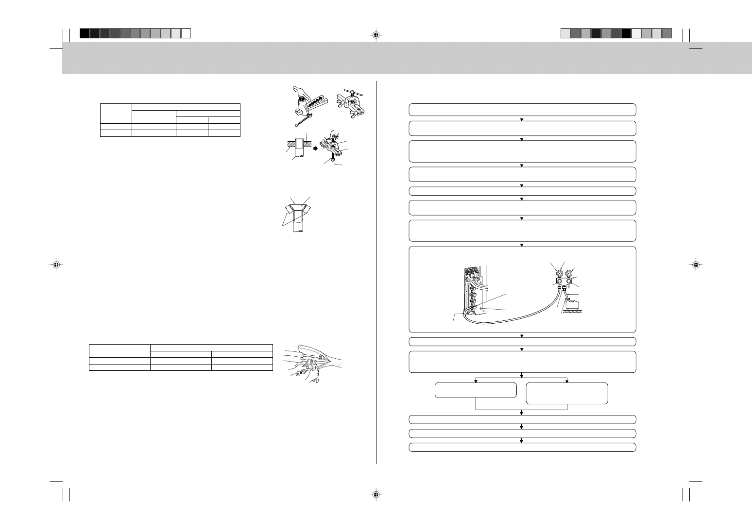
PURGING PROCEDURES
Connect the refrigerant pipes (both liquid pipe and gas pipe) between the indoor and
the outdoor unit.
Remove the service port cap of the stop valve on the gas pipe side of the outdoor unit.
(The stop valve will not work in it initial state fresh out of the factory [totally closed with
cap on].)
Connect the gauge manifold valve and the vacuum pump to the service port of the stop
valve on the gas pipe side of the outdoor unit.
Run the vacuum pump. (Vacuumize for more than 15 minutes.)
Check the vacuum with the gauge manifold valve, then close the gauge manifold valve
and stop the vacuum pump.
Leave it as is for one or two minutes. Make sure the pointer of the gauge manifold
valve remains in the same position. Confirm that the pressure gauge shows –0.101
MPa [Gauge] (–760 mmHg).
Pipe length up to 20 m
No gas charge is needed.
Pipe length exceeding 20 m
Charge the prescribed
amount of gas. (refer to 5-1)
Remove the gauge manifold valve quickly from the service port of the stop valve.
After refrigerant pipes are connected and evacuated, fully open all stop valves on both
sides of gas pipe and liquid pipe.
Operating without fully opening lowers the performance and this causes trouble.
Tighten the cap to the service port to obtain the initial status.
Retighten the cap.
Leak test
(or the vacuum
pump with the
function to prevent
the back flow)
Gauge manifold
valve (for R410A)
Pressure gauge
(for R410A)
Compound pressure
gauge (for R410A)
-0.101MPa
(-760 mmHg)
Handle
Low
Handle High
Window
Charge hose (for R410A)
Vacuum
pump
Adapter for
preventing
the back flow
Charge hose
(for R410A)
Stop valve
(gas side)
Service port
* Perform the purging procedures
on both Å unit and ı unit sides.
7
ON
ON
ON
ON
ON
WARNING:
When installing or moving the unit, do not mix anything other than specified refrigerant (R410A) into
the refrigerating cycle.
If air is mixed, it may cause the refrigerating cycle to get abnormally high temperature, causing a risk of
burst.
Tightening torque
N·m
kgf·cm
Cap for service port
13.7 to 17.7
140 to 180
Cap for stop valve
19.6 to 29.4
200 to 300
5-5
EARTHING WORK
Put the earth circuit to the ground in accordance with “Technical Standards for Electrical Installation”.
CAUTION:
Do not connect the earth cable to any gas pipe, water pipe, lightening rod or telephone earth cable.
If there is some deficiency in earthing work, it may cause a risk of electric shock.
The product incorporates a frequency inverter and so requires earthing in order to observe electric charge and
noise caused by static electricity.
5-6
LOCKING THE OPERATION MODE OF THE AIR CONDITIONER (COOL,
DRY, HEAT)
• Description of the function:
With this function, you can lock the operation mode of
the outdoor unit. Once the operation mode is locked to
either COOL/DRY mode or HEAT mode, the air condi-
tioner operates in that mode only.
* Initial setting is required to activate this function. Please
explain about this function to your customers and ask
them whether they want to use it.
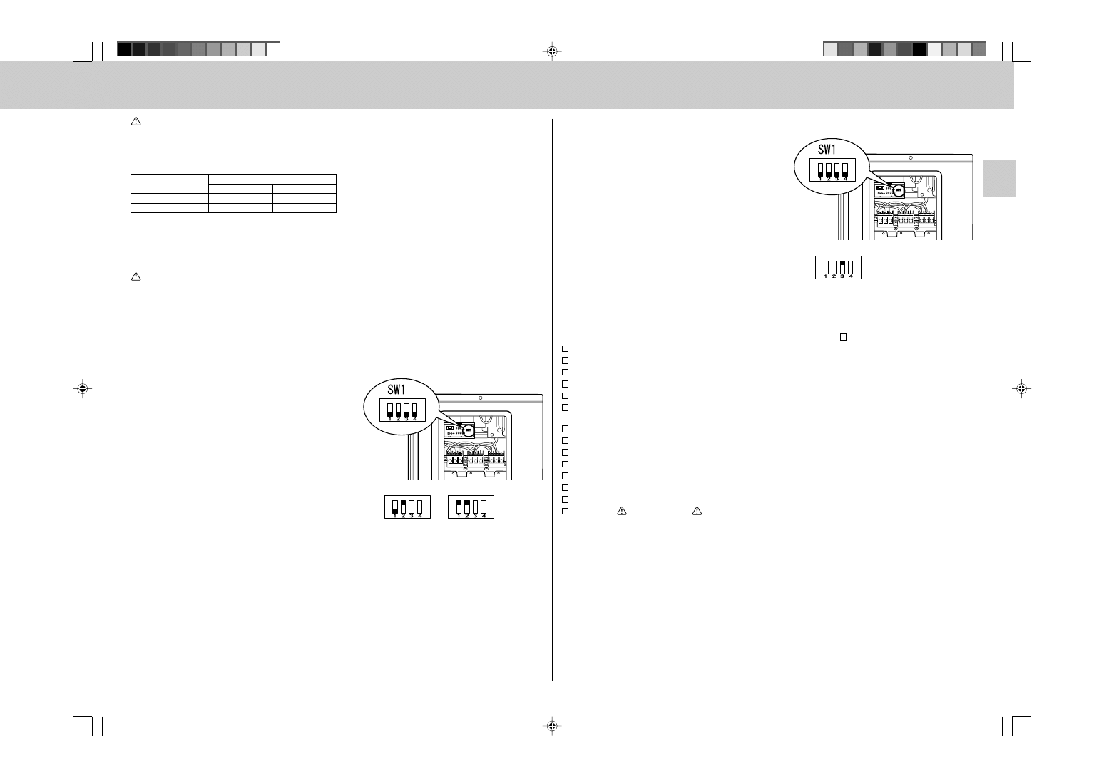
[How to lock the operation mode]
1 Be sure to turn off the main power for the air conditioner
before making the setting.
2 Set the 2nd Dip Switch of SW1 on the outdoor controller
board to ON to enable this function.
3 To lock the operation mode in COOL/DRY mode, set the
1st Dip Switch of SW1 on the outdoor controller board to
OFF. To lock the operation in HEAT mode, set the same
switch to ON.
4 Turn on the main power for the air conditioner.
COOL/DRY
HEAT
5-7
LOWERING THE OPERATING NOISE OF THE OUTDOOR UNIT
• Description of the function:
With this function, you can lower the operating noise of
the outdoor unit when the operation load is small, for ex-
ample, during nighttime in COOL mode. However, please
note that the cooling and heating capacity can also be
lowered if this function is activated.
* Initial setting is required to activate this function. Please
explain about this function to your customers and ask
them whether they want to use it.
[How to lower the operating noise]
1 Be sure to turn off the main power for the air conditioner
before making the setting.
2 Set the 3rd Dip Switch of SW1 on the outdoor controller
board to ON to enable this function.
3 Turn on the main power for the air conditioner.
5-8
CHECKING AFTER INSTALLATION
After finishing the installation, check the following items again by marking .
Have special circuits been provided?
Is power supply voltage as specified?
Has indoor/outdoor connecting wire been inserted into terminal block?
Has indoor/outdoor connecting wire been secured firmly?
Has intermediary connection between power cable and indoor/outdoor connecting wire been carried out?
Is combination of connection pipes and indoor/outdoor connecting wire correct (Room A, Room B, Room C,
Room D)?
Is earth cable connection correct?
Has leak test been carried out?
Has air purge been carried out?
Is stop valve fully open?
Has drain discharge been checked?
Is insulation over connection pipe joints correct?
Is strength of installation location well enough?
Have all of
WARNING and
CAUTION items in “1. THE FOLLOWING SHOULD ALWAYS BE OB-
SERVED FOR SAFETY” been checked?
5-9
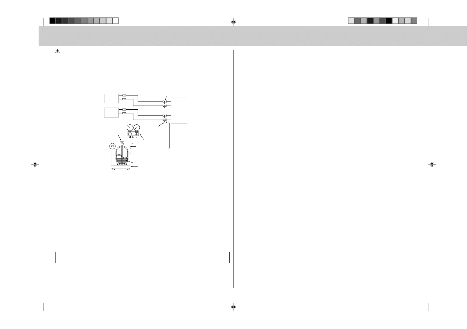
GAS CHARGE
Perform gas charge to unit.
1 Connect gas cylinder to the service port of stop valve.
2 Perform air purge of the pipe (or hose) coming from refrigerant gas cylinder.
3 Replenish specified amount of the refrigerant, while operating the air conditioner for cooling.
Note:
In case of adding refrigerant, comply with the quantity specified for the refrigerating cycle.
Lower the operating
noise
8
CAUTION:
When charging the refrigerant system with additional refrigerant, be sure to use liquid refrigerant. Add-
ing gas refrigerant may change the composition of the refrigerant in the system and affect normal
operation of the air conditioner. Also, charge the system slowly, otherwise the compressor will be
locked.
To maintain the high pressure of the gas cylinder, warm the gas cylinder with warm water (under 40°C) during
cold season. But never use naked fire or steam.
5-10 TEST RUN
• Be sure to perform the test run for each unit. Make sure each indoor unit operates properly following the
installation manual attached to the unit.
• If you perform the test run for all indoor units at once, you cannot detect any erroneous connection, if any, of
the refrigerant pipes and the indoor/outdoor unit connecting wires.
About the restart protective mechanism
Once the compressor stops, the restart preventive device operates so the compressor will not operate for 3
minutes to protect the air conditioner.
5-11 EXPLANATION TO THE CUSTOMER
• Recommend the customer to read the OPERATING INSTRUCTIONS carefully.
• Using the OPERATING INSTRUCTIONS for each unit, explain the following to the customer, how to control
temperature, how to remove the air filters, how to remove or put the remote controller in the remote controller
holder, how to clean, precautions for operation, etc.
If the customer (user) is absent, explain to the purchaser (owner, building’s controller, etc) about those
points.
Indoor
unit
Union
Stop valve
Outdoor
unit
Indoor
unit
Union
Service port
Gauge manifold
valve (for R410A)
Charge hose (forR410A)
Refrigerant gas
cylinder
operating valve
(for R410A)
Refrigerant gas cylinder
for R410A with siphon
Refrigerant (liquid)
Electronic scale for
refrigerant charging
Liquid pipe
Gas pipe
Liquid pipe
Gas pipe

HEAD OFFICE: TOKYO BLDG., 2-7-3, MARUNOUCHI, CHIYODA-KU, TOKYO 100-8310, JAPAN
AUTHORIZED REPRESENTATIVE IN EU:
MITSUBISHI ELECTRIC EUROPE B.V.
HARMAN HOUSE, 1 GEORGE STREET, UXBRIDGE, MIDDLESEX UB8 1QQ, U.K.
SG79Y760H04
This product is designed and intended for use in the residential,
commercial and light-industrial environment.
The product at hand is based on
the following EU regulations:
• Low Voltage Directive 2006/95/EC
• Electromagnetic Compatibility Directive 2004/108/EC
Wyszukiwarka
Podobne podstrony:
IM PAR21MAA WT05598X01 GB 04 2009
IM PCFY P40 125VKM E RG79D452H01 GB 01 2009
IM PEFY P15 63VMS1 L E KB79H130H03 GB 08 2009
IM PAC IF011B E IF012B E BH79D099H02 GB 09 2009
IM MS MSH GD80VB JG79A087H01 GB 04 2008
IM CMY Y G2 WT05132X01 GB 04 2008
IM MSH MS GE50VB E1 JG79A149H01 GB 02 2009
IM PUHZ HRP71 100 125VHA2 YHA2 RG79D355H03 GB 01 2009
IM MSZ MUZ HC25 35VA SG79Y763H07 GB 01 2010
IM PAC SE51CRB WT03594X05 GB Aug 2009
IM MSC GE20 35VB E1 JG79A172H01 GB 02 2009
IM MXZ 8A140VA BG79U438H05 GB 11 2007
IM CMY Q100VBK WT05688X01 GB Aug 2009
Podobno złapali szefa irackiej al Kaidy (24 04 2009)
21,04,2009
więcej podobnych podstron