Interface
(Cased)
PAC-IF011B-E
PAC-IF012B-E
TIL INSTALLATØREN
FÖR INSTALLATÖREN
PARA O INSTALADOR
PER L’INSTALLATORE
PARA EL INSTALADOR
VOOR DE INSTALLATEUR
POUR L’INSTALLATEUR
FÜR INSTALLATEURE
FOR INSTALLER
Emniyetli ve doğru kullanım için, klima cihazını monte etmeden önce bu kılavuzu ve iç ünite montaj kılavuzunu
tamamıyla okuyun.
INSTALLATION MANUAL
For safe and correct use, read this manual and the indoor unit installation manual thoroughly before installing
the air-conditioner unit.
INSTALLATIONSHANDBUCH
Aus Sicherheitsgründen und zur richtigen Verwendung vor der Installation die vorliegende Bedienungsanleitung
und die Installationsanleitung der Innenanlage gründlich durchlesen die Klimaanlage.
MANUEL D’INSTALLATION
Avant d’installer le climatiseur, lire attentivement ce manuel, ainsi que le manuel d’installation de l’appareil
intérieur pour une utilisation sûre et correcte.
INSTALLATIEHANDLEIDING
Lees deze handleiding en de installatiehandleiding van het binnenapparaat zorgvuldig door voordat u met het
installeren van de airconditioner begint.
MANUAL DE INSTALACIÓN
Para un uso correcto y seguro, lea detalladamente este manual y el manual de instalación de la unidad interior
antes de instalar la unidad de aire acondicionado.
MANUALE DI INSTALLAZIONE
Per un uso sicuro e corretto, leggere attentamente il presente manuale ed il manuale d’installazione dell’unità
interna prima di installare il condizionatore d’aria.
MANUAL DE INSTALAÇÃO
Para uma utilização segura e correcta, leia atentamente este manual e o manual de instalação da unidade
interior antes de instalar o aparelho de ar condicionado.
INSTALLATIONSMANUAL
Læs af sikkerhedshensyn denne manual samt manualen til installation af indendørsenheden grundigt, før du
installerer klimaanlægget.
INSTALLATIONSMANUAL
Läs bruksanvisningen och inomhusenhetens installationshandbok noga innan luftkonditioneringen installeras
så att den används på ett säkert och korrekt sätt.
Türkçe (TR)
(RU)
English (GB)
Deutsch (D)
Français (F)
Nederlands (NL)
Español (E)
Italiano (I)
Eλληνικά (GR)
Português (P)
Dansk (DE)
Svenska (SW)
Contents
1. Safety
precautions
..................................................................................... 2
2. Installing the interface unit ......................................................................... 3
3. Electrical
work
........................................................................................... 4
Guide to plan local applications ................................................................. 8
1. Safety precautions
Before installing the interface unit, make sure you read all the “Safety
precautions”.
Please report to your supply authority or obtain their consent before
connecting this equipment to the power supply system.
Warning:
Precautions that must be observed to prevent injuries or death.
Caution:
Precautions that must be observed to prevent damages to the unit.
After installation, perform the test run to ensure normal operation. Then explain the
“Safety Precautions,” use, and maintenance of the unit based on the information in
the Operation Manual to your customer. Both the Installation Manual and the Op-
eration Manual must be given to the user. These manuals must always be kept by
the actual users.
: Indicates a part which must be grounded.
Warning:
Carefully read the labels attached to the unit.
Warning:
• The unit must not be installed by the user. Ask an installer or an authorised
technician to install the unit. If the unit is installed improperly, electric
shock, or fi re may be caused.
• For installation work, follow the instructions in the Installation Manual and
use tools and pipe components specifi cally made for use with refrigerant
specifi ed in the outdoor unit installation manual.
• The unit must be installed according to the instructions in order to mini-
mize the risk of damages by earthquakes, typhoons, or strong winds.
Improperly installed unit may fall down and cause damage or injury.
• The unit must be securely installed on a structure that can sustain its weight.
If the unit is mounted on an unstable structure, it may fall down and cause
damage or injury.
• All electric work must be performed by a qualifi ed technician according to
local regulations and the instructions given in this manual. The unit must
be powered by dedicated power lines and the correct voltage and circuit
breakers must be used. Power lines with insuffi cient capacity or incorrect
electrical work may result in electric shock or fi re.
•
Only the specified cables can be used for wiring. Connections must be
made securely without tension on the terminals. If cables are connected or
installed improperly, It may result in overheating or fi re.
•
Terminal block cover panel of the unit must be fi rmly fi xed. If the cover
panel is mounted improperly, dust and moisture may enter the unit, and it
may cause electric shock or fi re.
•
Make sure to use accessories authorised by Mitsubishi Electric and ask
an installer or an authorised technician to install them. If accessories are
improperly installed, it may cause electric shock, or fi re.
•
Do not remodel the unit. Consult an installer for repairs. If alterations or
repairs are not performed correctly, it may cause electric shock or fi re.
•
The user should never attempt to repair the unit or transfer it to another
location. If the unit is installed improperly, it may cause electric shock or
fi re. If the interface unit needs to be repaired or moved, ask an installer or
an authorised technician.
1.1. Before installation (Environment)
Caution:
• Do not install the interface unit in outdoor location as it is designed for
indoor installation only. Otherwise electric shock or breakdown may be
caused by water drop, wind or dust.
• Do not use the unit in an unusual environment. If the interface unit is installed
or exposed to steam, volatile oil (including machine oil), or sulfuric gas, or
exposed to briny air, the internal parts can be damaged.
• Do not install the unit where combustible gases may leak, be produced,
fl ow, or accumulate. If combustible gas accumulates around the unit, it may
cause fi re or explosion.
• When installing the unit in a hospital or in a building where communica-
tions equipment are installed, you may need to take measure to noise and
electronic interference. Inverters, home appliances, high-frequency medical
equipment, and radio communications equipment can cause the interface
unit to malfunction or to breakdown. At the same time, the noise and elec-
tric interference from the interface unit may disturb the proper operation of
medical equipment, and communications equipment.
1.2. Before installation or relocation
Caution:
• Be very careful when moving the units. Do not hold the packaging bands.
Wear protective gloves to unpack and to move it, in order to avoid your
hands being injured by parts.
1.3. Before electric work
Caution:
•
Be sure to install a circuit breaker. If it is not installed, there may be a risk
of electric shock.
•
For the power lines, use standard cables of suffi cient capacity. Otherwise,
it may cause a short circuit, overheating, or fi re.
•
When installing the power lines, do not apply tension to the cables. The
cables may be cut or overheated resulting in a fi re.
•
Make sure to ground the unit. Do not connect the ground wire to gas or
water pipes, lightning rods, or telephone grounding lines. If the unit is not
properly grounded, there may be a risk of electric shock.
•
Make sure to use circuit breakers (ground fault interrupter, isolating switch
(+B fuse), and molded case circuit breaker) with the specifi ed capacity. If
the circuit breaker capacity is larger than the specified capacity, break-
down or fi re may result.
Note (Marking for
WEEE)
• Be sure to safely dispose of the packaging materials. Packaging materials,
such as nails and other metal or wooden parts may cause injury.
• Do not wash the interface unit. You may receive an electric shock.
This symbol mark is for EU countries only.
This symbol mark is according to the directive 2002/96/EC Article 10 Information for users and Annex IV.
Your MITSUBISHI ELECTRIC product is designed and manufactured with high quality materials and components which can be recycled and reused.
This symbol means that electronic equipment, at the end-of-life, should be disposed of separately from your household waste.
Please, dispose of this equipment at your local community waste collection/recycling centre.
In European Union there are separate collection systems for used electrical and electronic products.
Please, help us to conserve the environment we live in.
2
GB
2. Installing the interface unit
Fig. 2-1
IF011
IF012
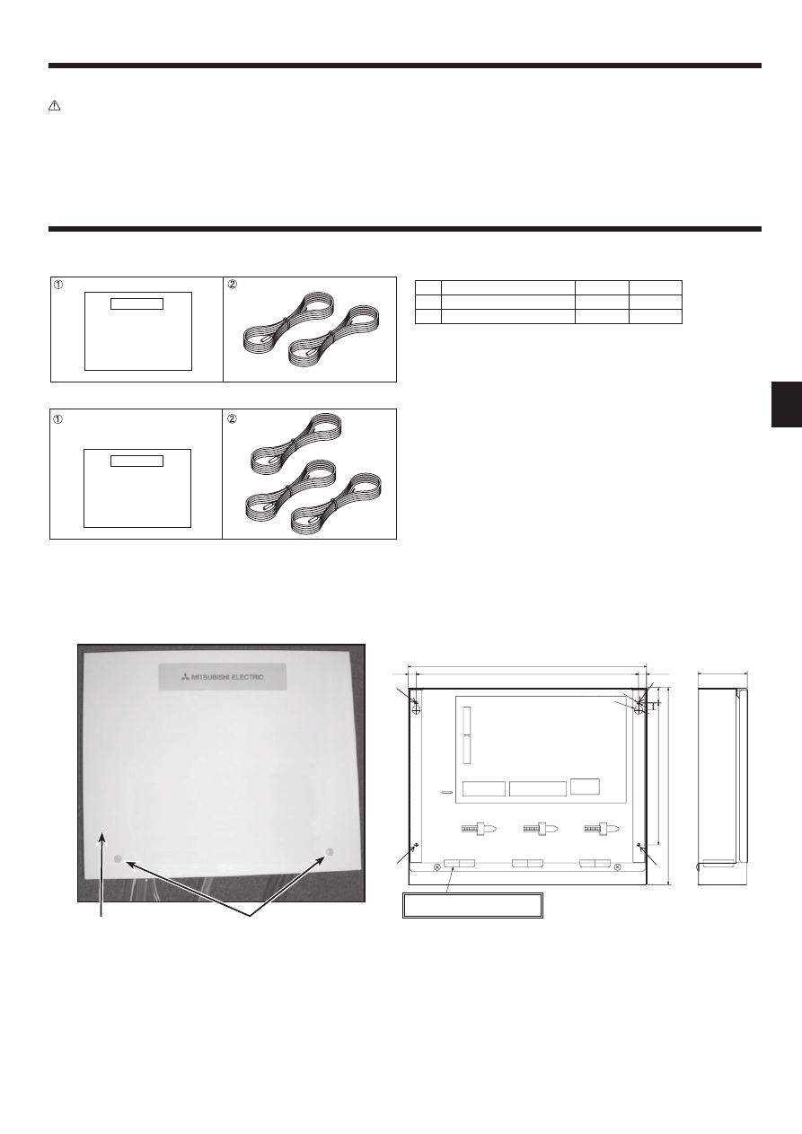
2.1. Check the parts (Fig. 2-1)
The interface unit should be supplied with the following parts.
Part Name
IF011
IF012
1
Interface unit
1
1
2
Thermistor
2
3
2.3. Installing the interface unit (Fig. 2-2, Photo.2-1)
1. Remove 2 screws from interface unit and remove the cover.
2. Install the 4 screws (locally supplied) in 4 holes.
A
Screw B Cover
C
Hole for installation
1.4. Before starting the test run
Caution:
•
Turn on the main power switch of the outdoor unit more than 12 hours
before starting operation. Starting operation immediately after turning on
the power switch can severely damage the internal parts. Keep the main
power switch turned on during the operation period.
•
Before starting operation, check that all protective parts are correctly in-
stalled. Make sure not to get injured by touching high voltage parts.
•
Do not touch any switch with wet hands. There may be a risk of electric
shock.
•
After stopping operation, wait at least 5 minutes before turning off the
main power. Otherwise, it may cause breakdown.
2.2. Choosing the interface unit installation location
• Do not install the interface unit in outdoor location as it is designed for indoor
installation only. (The interface board and casing are not waterproof.)
•
Avoid locations where the unit is exposed to direct sunlight or other sources of
heat.
•
Select a location where easy wiring access to the power source is available.
•
Avoid locations where combustible gases may leak, be produced, fl ow, or accu-
mulate.
•
Select a level location that can bear the weight and vibration of the unit.
•
Avoid locations where the unit is exposed to oil, steam, or sulfuric gas.
22
(11.5)
Unit:mm
11.5
:5
:12
10
200
313
3-ELECTRIC WIRE INLET
When installed on a wall: Lower side
278
336
69
TB61
TB62
TB141
TB142
TB6
Fig.2-2
Photo.2-1
B
A
1. Safety precautions
3
GB
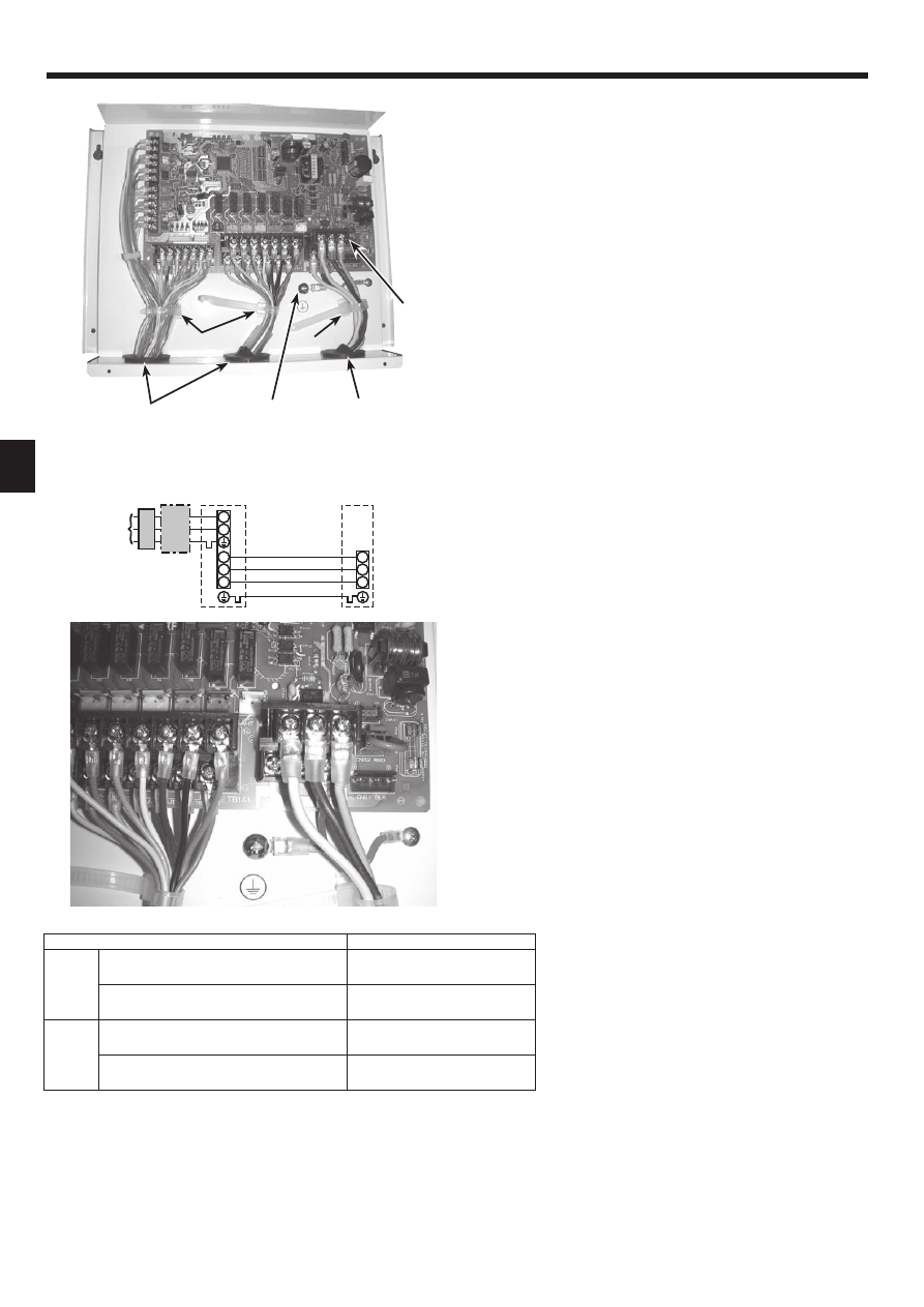
3. Electrical work
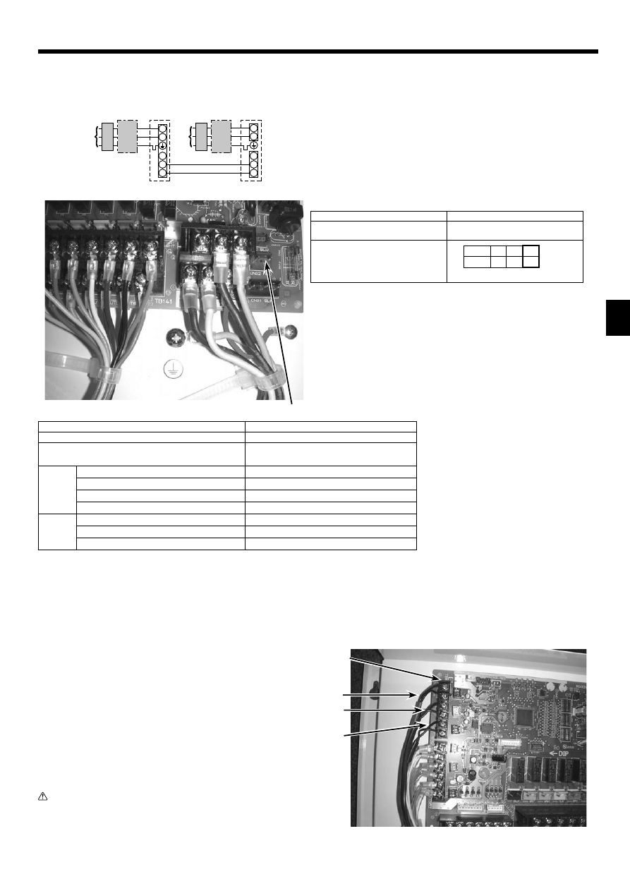
3.1. Interface unit (Photo. 3-1)
1. Remove the cover.
2. Wire the power cable and control cable separately through the respective wiring
inlets given in the photo.
• Do not allow slackening of the terminal screws.
A
Inlet for control cable
B
Inlet for power
C
Clamp
D
Interface / Outdoor unit connecting terminals
E
Earth terminal
3.1.1. Interface unit power supplied from outdoor unit
The following connection patterns are available.
The outdoor unit power supply patterns vary on models.
1 System
S1
S2
L
N
S1
S2
S3
S3
A
B
C
D
E
F
A Outdoor unit power supply
B Earth leakage breaker
C Wiring circuit breaker or isolating switch
D Outdoor unit
E Interface unit/outdoor unit connecting cables
F Interface unit
*1. Max. 80 m
*2. The fi gures are NOT always against the ground.
S3 terminal has DC 24 V against S2 terminal. However between S3 and S1, these terminals are not electrically insulated by the transformer or other device.
Notes: 1. Wiring size must comply with the applicable local and national code.
2.
Power supply cables and interface unit/outdoor unit connecting cables shall not be lighter than polychloroprene sheathed fl exible cable.
(Design 60245 IEC 57)
3. Install an earth longer than other cables.
Photo.3-2
Photo.3-1
A
B
C
E
C
D
Interface unit model
PAC-IF011/012B-E
Interface unit-Outdoor unit *1
3 × 1.5 (polar)
Interface unit-Outdoor unit earth *1
1 × Min. 1.5
Interface unit-Outdoor unit S1-S2 *2
AC 230 V
Interface unit-Outdoor unit S2-S3 *2
DC24 V
Wiring
Wire No. × size
(mm²)
Circuit
rating
4
GB
3. Electrical work
3.1.2. Separate interface unit/outdoor unit power supplies
The following connection patterns are available.
The outdoor unit power supply patterns vary on models.
1:1 System
S1
S2
L
N
L
N
S1
S2
S3
S3
A
C
B
D
G
E
B
C
F
A Outdoor unit power supply
B Earth leakage breaker
C Wiring circuit breaker or isolating switch
D Outdoor unit
E Interface unit/outdoor unit connecting cables
F Interface unit
G Interface unit power supply
If the interface and outdoor units have separate power supplies, refer to the table below.
Interface unit controller connector
(CNS2) connection change
Outdoor unit DIP switch settings (when
using separate interface unit/outdoor
unit power supplies only)
Separate power supply specifi cations
Disconnected
ON
OFF
1
2
(SW8)
3
Set the SW8-3 to ON.
*1. A breaker with at least 3.0mm contact separation in each pole shall be provided. Use earth leakage breaker (NV).
*2. Max. 120 m
*3. The fi gures are NOT always against the ground.
Notes: 1. Wiring size must comply with the applicable local and national code.
2.
Power supply cables and interface unit/outdoor unit connecting cables shall not be lighter than polychloroprene sheathed fl exible cable.
(Design 60245 IEC 57)
3. Install an earth longer than other cables.
Photo.3-3
3.1.3. Connecting thermistor cable
Connect the thermistor 2 for the interface controller.
1. Target temp. thermistor (TH1)
Connect the thermistor for the target temp. to 1 and 2 on the terminal block (TB61)
on the interface controller.
2. Pipe temp. thermistor / Liquid (TH2)
Connect the thermistor for the pipe temp. to 3 and 4 on the terminal block (TB61)
on the interface controller.
3. Cond./eva. temp. thermistor (TH5): For PAC-IF012B-E only
Connect the thermistor for the cond./eva. temp. to 5 and 6 on the terminal block
(TB61) on the interface controller.
When the thermistor cables are too long, cut it to the appropriate length.
Do not bind it in the interface unit.
Caution:
Do not route the thermistor cables together with power cables.
The sensor part of the thermistor should be installed where user
must not touch.
(It is separated by the supplementary insulation from where user
may touch.)
Photo.3-4
CNS2
TB61
TH2
Interface unit model
PAC-IF011/012B-E
Interface unit power supply
~/N (Single Phase), 50 Hz, 230 V
Interface unit input capacity *1
Main switch (Breaker)
16 A
Interface unit power supply
2 × Min. 1.5
Interface unit power supply earth
1 × Min. 1.5
Interface unit-Outdoor unit *2
2 × Min. 0.3
Interface unit-Outdoor unit earth
—
Interface unit L-N *3
AC 230 V
Interface unit-Outdoor unit S1-S2 *3
—
Interface unit-Outdoor unit S2-S3 *3
DC24 V
Wiring
Wire No. × size
(mm²)
Circuit
rating
TH5
TH1
5
GB
3. Electrical work
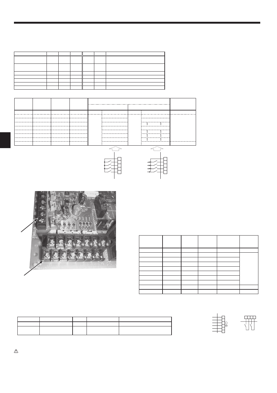
3.1.4. Connecting external input
Demand control is available by external input.
It is possible to set the outdoor unit’s power consumption by setting the switch of the interface controller.
• REMOTE SWITCH Type A (4bit - 8 setting) / Type B (1bit -1 setting)
Demand control is available by connecting remote switches with terminal No.10 - 14.
Make sure to use the non-voltage switch (for the remote switch)
Remote switch cable length : Maximum 10m
Remote switch : Minimum applicable load DC12V, 1mA
• 4-20mA / 1-5V / 0-10V / 0-10kΩ
1
Use 4-20mA / 1-5V / 0-10V
Connect the transmission cables to No. 3 and 4 on the terminal block (TB62).
No. 3 on the terminal block(TB62) : Plus side
No. 4 on the terminal block(TB62) : Minus side (Reference side)
2
Use adjustable resistor (0-10kΩ)
Connect the transmission cables to No. 1 and 2 on the terminal block (TB62).
Adjustable
resistor
(0-10kΩ)
4-20mA
1-5V
0-10V
Step for
capacity
setting
Remark
0~100Ω
4~5mA
0~1.25V
0~0.63V
OFF 0% Stop
510Ω
7mA
1.75V
1.88V
Step1 10%
Hz fi xed
mode
1kΩ
9mA
2.25V
3.13V
Step2 20%
2kΩ
11mA
2.75V
4.38V
Step3 30%
3.3kΩ
13mA
3.25V
5.63V
Step4 50%
4.3kΩ
15mA
3.75V
6.88V
Step5
70%
5.6kΩ
17mA
4.25V
8.13V
Step6 80%
7.5kΩ
19~20mA
4.75~5V
9.38~10V
Step7 100%
10kΩ
–
–
–
Auto
Auto mode
OPEN(12kΩ~)
–
–
–
OFF 0% Stop
*The value of the above-mentioned table becomes the center of the input value.
Cable length : Maximum 10m
Step for capacity setting
TB142
10-11
(COM-IN5)
TB142
10-12
(COM-IN6)
TB142
10-13
(COM-IN7)
TB142
10-14
(COM-IN8)
Remark
Auto mode
OFF
Hz fixed
mode
TB142
I/F
10
11
12
13
14
10
11
12
13
14
At site
OFF〜AUTO
TB142
I/F
At site
Step1
Step4
Step7
AUTO
OFF
ON
OFF
ON
OFF
ON
OFF
ON
OFF
OFF
OFF
ON
ON
OFF
OFF
ON
ON
OFF
OFF
OFF
OFF
OFF
ON
ON
ON
ON
OFF
OFF
OFF
OFF
OFF
OFF
OFF
OFF
OFF
ON
OFF 0%
Step1 10%
Step2 20%
Step3 30%
Step4 50%
Step5 70%
Step6 80%
Step7 100%
Auto
OFF 0%
Step1 10%
Step4 50%
Step7 100%
Auto
[OFF]
[ON]
[OFF]
[ON]
TypeA
TypeB
{
Input
SW 1-1 SW 1-2 SW 1-3 SW 6-1 SW 6-2
Step for capacity setting
REMOTE SWITCH
Type A (4bit-8 setting)
OFF
OFF
OFF
OFF
OFF
OFF/Step1/Step2/…/Step7/Auto
REMOTE SWITCH
Type B (1bit-1 setting)
ON
OFF
OFF
OFF
OFF
OFF/Step1/Step4/Step7/Auto
4-20mA
ON
ON
OFF
ON
ON
OFF/Step1/Step2/…/Step7
1-5V
ON
ON
OFF
OFF
ON
OFF/Step1/Step2/…/Step7
0-10V
OFF
OFF
ON
OFF
OFF
OFF/Step1/Step2/…/Step7
0-10kΩ
ON
OFF
ON
OFF
OFF
OFF/Step1/Step2/…/Step7/Auto
No input (AUTO mode)
OFF
ON
ON
OFF
OFF
Only Auto mode
Switch1, Switch 6 : Input selection of inverter capacity setting
Photo.3-5
TB142
• External function setting
This function is setting operation mode or stopping compressor, by the external signal.
TB142
Item
OFF
ON
Remark
1-2 (IN1)
Forced Comp. OFF
Normal
Forced Comp. OFF
3-4 (IN2)Item Fixed operation mode Cooling Heating
Available when SW2-1 and SW2-2
are ON
Cable length : Maximum 10m
Remote switch : Minimum applicableload DC12V, 1mA
Caution:
The external input signals are separated by basic insulation from power supply for the unit.
The external input signals should be separated by supplementary insulation from where user may touch in case that it is installed where
user may touch.
Connect the terminals by using the ring terminals and also insulate the cables of adjoining terminals when wiring to terminal block.
2
1
3 4
TB142
I/F
At site
I/F
At site
6
5
2
1
4
3
0-10 kΩ
TB62
4-20mA/1-5V/0-10V
Wired remote controller
(For maintenance)
+
TB62
6
GB
3. Electrical work
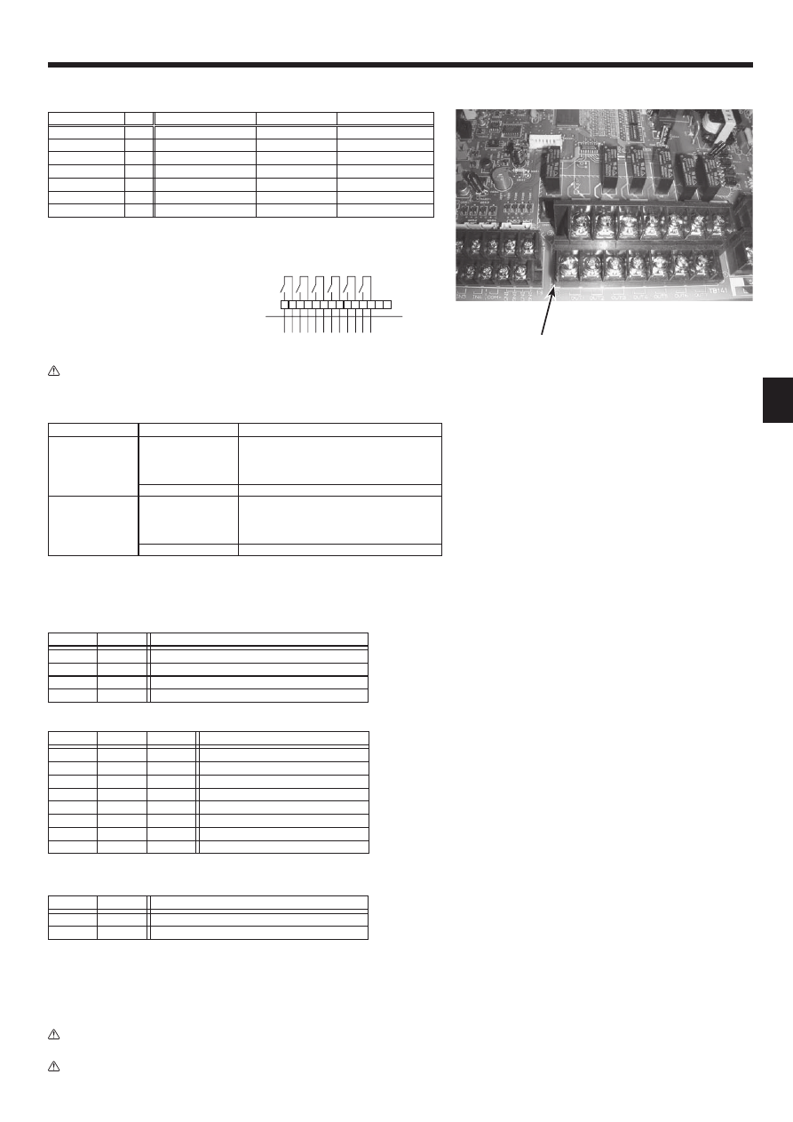
3.1.5. Connecting External Output
The signal in the following states can be output.
TB141 Item OFF
ON
1-2
(OUT1)
X1
Operation Output
OFF
ON
3-4 (OUT2)
X2
Error
Output
Normal
Error
5-6
(OUT3)
X3 Comp. Output
OFF(Comp. OFF) ON
(Comp. ON)
7-8 (OUT4)
X4
Defrost
Output
OFF
ON (Defrosting)
9-10 (OUT5)
X5
Mode(Cool)
Output
OFF
ON (Cooling)
11-12 (OUT6)
X6 Mode(Heat)
Output
OFF
ON (Heating)
13-14 (OUT7)
–
–
–
–
Cable length : Maximum 50m
Output specifi cation : Non-voltage switch 1A or less , 240V AC
*Connect the surge absorber according to the load at site.
2
1
3
5
4
6 7 8
TB141
9 10 11 12 13 14
X1
I/F
At site
X2 X3 X4 X5 X6
Note : External output signals are separated by basic insulation from other circuit of
interface.
Caution : When 2 or more external outputs are used, the power supply on the output
side should be the same.
3.1.7. Switch setting
It is possible to set the following function by setting the switch of the interface controller.
Set switches in case of auto mode.
Photo.3-6
TB141
3.1.6. Wiring specifi cation External output / External input
Locally supplied parts
Item
Name
Model and specifi cations
External output function External output signal wire Use sheathed vinyl coated cord or cable.
Wire type : CV, CVS or equivalent.
Wire size : Stranded wire 0.5mm
2
to 1.25mm
2
Solid wire: {0.65mm to {1.2mm
Display lamp, etc.
Non-voltage Contact AC220-240V (DC30V), 1A or less
External input function
External input signal wire
Use sheathed vinyl coated cord or cable.
Wire type : CV, CVS or equivalent.
Wire size : Stranded wire 0.5mm
2
to 1.25mm
2
Solid wire : {0.65mm to {1.2mm
Switch
Non-voltage "a" contact
3.1.8.Before test run
After completing installation and the wiring and piping of the local application and outdoor units, check for refrigerant leakage, looseness in the power supply or control
wiring, wrong polarity, and no disconnection of one phase in the supply.
Use a 500-volt megohmmeter to check that the resistance between the power supply terminals and ground is at least 1.0MΩ.
Warning:
Do not use the system if the insulation resistance is less than 1.0MΩ.
Caution:
Do not carry out this test on the control wiring (low voltage circuit) terminals.
SW2-1
SW2-2
Details
OFF
OFF
Not FIX (Depending on Remote controller setting)
ON
OFF
[Cooling] FIX
OFF
ON
[Heating] FIX
ON
ON
External input (Depending on TB142-3, 4)
• SW2-1/2-2 : Fixed operation mode
SW2-3
SW2-4
SW2-5
Details
OFF
OFF
OFF
Not fi xed (Remote controller setting)
ON
OFF
OFF
Cooling 19°C/Heating 17°C FIX
OFF
ON
OFF
20°C FIX
ON
ON
OFF
22°C FIX
OFF
OFF
ON
24°C FIX
ON
OFF
ON
26°C FIX
OFF
ON
ON
28°C FIX
ON
ON
ON
Cooling 30°C/Heating 28°C FIX
• SW2-3/2-4/2-5 : Fixed set temperature [For Auto mode only]
SW2-6
Details
Model
OFF
Effect
PAC-IF012B-E
ON
No effect
PAC-IF011B-E
• SW2-6 : COND./EVA. TEMP. THERMISTOR (TH5)
7
GB
Local Application Factors
* This interface is to connect Mr. Slim inverter outdoor unit of MITSUBISHI ELECTRIC to local applications. Please check the
following when designing the local system.
* MITSUBISHI ELECTRIC does not take any responsibility on the local system design.
1. Heat exchanger
(1)
Withstanding
pressure
Designed pressure of outdoor unit is 4.15 MPa. Following must be satisfied for burst pressure of connecting application.
Burst pressure : More than 12.45 MPa (3 times more than designed pressure)
(2)
Performance
Secure the heat exchanger capacity which meets the following conditions. If the conditions are not met, it may result in
malfunction caused by the protection operation or the outdoor unit may be turned off due to the operation of protection
system.
1. Evaporate temperature is more than 4 in max. frequency operation under
+1
the cooling rated conditions.
2. Condense temperature is less than 60 in max. frequency operation under
+2
the heating rated conditions.
3. In case of hot water supply, condense temperature is less than 58 in max. frequency operation with the
outside temperature 7D.B./6W.B.
+1. Indoor: 27D.B./19W.B. Outdoor:
35D.B./24W.B.
+2. Indoor: 20D.B.
Outdoor:
7D.B./6W.B.
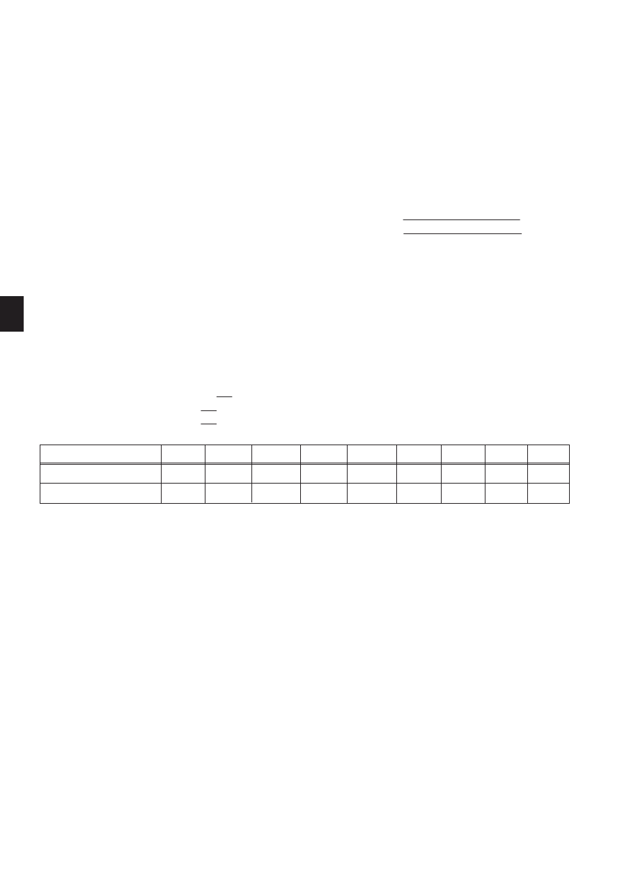
(3) Heat exchanger internal capacity
Heat exchanger internal capacity must be within the capacity range shown below. If the heat exchanger below the
minimum capacity is connected, it may result in the back flow of liquid or the failure of the compressor.
If the heat exchanger above the maximum capacity is connected, it may result in the deficiency in performance due to
lack of refrigerant or overheating of the compressor.
Minimum capacity : 10 % Model capacity [
)
] / Maximum capacity : 30 % Model capacity [
)
]
e.g. When connecting to PUHZ-RP100 VHA2
Minimum capacity : 10 % 100 =1000
)
Maximum capacity : 30 % 100 =3000
)
Maximum capacity [
)
]
Minimum capacity [
)
]
35
1050
350
50
1500
500
60
1800
600
71
2130
710
100
3000
1000
125
3750
1250
140
4200
1400
200
6000
2000
250
7500
2500
Model capacity
(4) Contamination maintenance
1. Wash the inside of heat exchanger to keep it clean. Be sure to rince not to leave flux. Do not use chlorine detergent
when washing.
2. Be sure that the amount of contamination per unit cubic content of heat transfer pipe is less than the following
amount.
Example) In case of :9.52mm
Residual water : 0.6,/", Residual oil : 0.5,/", Solid foreign object : 1.8,/"
2. Thermistor position
<Target temp.thermistor (TH1)> (Used only in *auto mode (Only for Air to Air applications))
1. Put thermistor (TH1) where average intake temperature for heat exchanger can be detected.
2. It is better to put thermistor (TH1) where radiant heat from heat exchanger can be avoided.
To use this interface for manual step control, put a fixed resistor of 4~10kΩ instead of thermistor (TH1 on the terminal
block TB61).
* Auto mode: In this mode, the capacity step of the outdoor unit is controlled automatically to let the target (intake)
temperature reach the setting temperature. (Only for air to air application)
<Liquid pipe thermistor(TH2)>
1. Put thermistor (TH2) where liquid refrigerant pipe temperature can be detected.
2. It is better to protect the thermistor (TH2) with heat insulating materials not to be affected by the ambient temperature, etc.
3. In case that the refrigerant is distributed by distributor, put thermistor (TH2) before the distributor.
<Cond./Eva. temp. thermistor (TH5)>
1. Put thermistor (TH5) where Cond./Eva. temperature can be detected on the indoor HEX pipe.
8
GB
BH79D099H02
This product is designed and intended for use in the residential,
commercial and light-industrial environment.
The product at hand is
based on the following
EU regulations:
• Low Voltage Directive 2006/95/EC
• Electromagnetic Compatibility Directive
2004/108/EC
HEAD OFFICE: TOKYO BLDG., 2-7-3, MARUNOUCHI, CHIYODA-KU, TOKYO 100-8310, JAPAN
Authorised representative in EU:
MITSUBISHI ELECTRIC EUROPE B.V.
HARMAN HOUSE, 1 GEORGE STREET, UXBRIDGE, MIDDLESEX UB8 1QQ, U.K.
Document Outline
- 01_BH79D099H02__EN.pdf
- 02_BH79D099H02__GE.pdf
- 03_BH79D099H01__FR.pdf
- 04_BH79D099H02__DU.pdf
- 05_BH79D099H01__SP.pdf
- 06_BH79D099H01__IT-WARNING.pdf
- 07_BH79D099H01_GR.pdf
- 08_BH79D099H01_PT.pdf
- 09_BH79D099H01_DA.pdf
- 10_BH79D099H01_SW.pdf
- 11_BH79D099H01_TK.pdf
- 12_BH79D099H01_RU.pdf
Wyszukiwarka
Podobne podstrony:
IM PCFY P40 125VKM E RG79D452H01 GB 01 2009
IM PEFY P15 63VMS1 L E KB79H130H03 GB 08 2009
IM PAC IF011B E RG79D377H01 pl
IM MXZ 2A30 52VA SG79Y760H04 GB 04 2009
IM PAC SE51CRB WT03594X05 GB Aug 2009
IM PAC SC36NA E(WT04936X01) GB
IM PAC SE51CRA WT02699X01 GB 2005
IM PAC YG81TB WT05422X02 Apr 2009
IM PAC YG83UTB WT05420X01 Apr 2009
IM MSH MS GE50VB E1 JG79A149H01 GB 02 2009
IM PAC AH125 140 250M H WT04980X02 GB 2007
IM PUHZ HRP71 100 125VHA2 YHA2 RG79D355H03 GB 01 2009
IM PAR21MAA WT05598X01 GB 04 2009
IM PAC YT51CRA WT03594X02 GB 2005
IM PAC SC51KUA J WT05372X03 Apr 2009
IM MSC GE20 35VB E1 JG79A172H01 GB 02 2009
więcej podobnych podstron