Contents
1. Safety Precautions ...................................................1
2. Product features.......................................................2
1. Specifications .................................................2
2. Power supply capacity....................................2
3. External Dimensions ......................................3
3. Installation ................................................................4
1. Parts List ........................................................4
2. Field-supplied Parts........................................4
3. Installation area and direction ........................4
4. Unit installation ...............................................5
4. Wiring .......................................................................5
1. Cover Removal and Installation .....................5
2. Power line.......................................................6
3. DC Power Supply and M-NET Transmission
Line.................................................................6
5. M-NET Transmission Lines Length........................10
Air-Conditioner Control System
Power supply unit
Model: PAC-SC51KUA
Installation Manual
Before using the controller, please read this Installation Manual carefully to ensure proper
operation. Retain this manual for future reference.
- 1 -
This manual details how to install the PAC-SC51KUA power supply unit and its wiring with the centralized controller and the indoor units.
For the information about how to install the centralized controller or the indoor units, see the appropriate installation manual.
For your safety, first read 1 Safety Precautions described below before installing the PAC-SC51KUA.
Store this manual in as easily accessible location. Make sure that this manual will be passed on to any future PAC-SC51KUA power
supply unit users.
1 Safety Precautions
Read all the “Safety Precautions” before installing this unit.
Follow at the “Safety Precautions” ; the information provides very important points regarding safety.
Symbols and Terms
Specific Precautions
WARNING
Statements identify conditions or practices that could result in personal injury or loss of life.
CAUTION
Statements identify conditions or practices that could result in damage to the unit or other property.
WARNING
CAUTION
The unit must be installed by a dealer or technical
representative.
Improper installation by an unqualified person may result in
electric shock and fire.
Install in a location that is strong enough to withstand
the weight of the unit.
A weak installation area may cause the unit to fall down,
resulting in a personal injury.
Only use specified cables. Securely connect each
cable so that the weight of the cable is not applied to
the connectors.
Loose or improper connections may result in heat
generation or fire.
Do not attempt to modify or repair the controller.
Modification or improper repair may result in electric shock
or fire.
Consult your dealer when repairs are necessary.
Make sure that the unit is powered by a dedicated line.
Other appliances connected to the same line could cause
an overload.
Make sure that there is a main power switch and
Ground-fault interrupter.
A ready accessible breaker for power source line helps
reduce the risk of electric shock. Installation of a breaker is
mandatory in some area.
Precisely follow the steps detailed in this manual for
proper installation.
Any deficiency caused by improper installation may result
in an electric shock or fire.
All electrical work must be performed by a licensed
technician, according to local regulations and the
instructions detailed in this manual.
Inadequate electric circuit or any deficiency caused by
improper installation may result in an electric shock or fire.
Ask your dealer or an authorized technician to move or
reinstall the controller.
Improper installation may result in an electric shock or fire.
This appliance must be grounded.
Make sure to install a protect PE (ground) wire.
Do not connect the PE (ground) wire to gas or water pipes,
lightning conductors, or telephone lines.
Improper grounding may cause an electric shock.
Securely install the cover (panel) of the PAC-SC51KUA.
If the cover (panel) is not installed properly, dust or water
may enter the unit and may result in fire or electric shock.
Do not install the controller where there is a risk of
flammable gas.
If the leaked gas accumulates around the controller, it may
ignite and cause an explosion.
Do not use the controller in an environment high in oil,
steam, or sulfuric gas.
These substances may have adverse effects on the
performance of the controller or damage its parts.
Install so that the wires are not subjected to any
tension.
Tension may cause the wires to break, overheating, or fire.
Do not wash the unit with water.
Doing so may cause an electric shock or malfunction.
Do not install in any area where the temperature could
be more than 55°C (131°F) or less than -10°C (14°F). Do
not expose to direct sunlight.
Use only a breaker and fuse of the specified capacity.
If breaker is not installed, it may cause an electric shock.
If a fuse and wire or copper wiring that has too large of a
capacity is used, it may cause the unit to malfunction or fire.
Do not install in a place that has the potential for
steam such as bath room or kitchen.
Steam may cause an electric shock or unit malfunction.
Do not install in any place where acidic, alkaline
solution, special spray, or other substances are used.
Doing so may cause an electric shock or unit malfunction.
Use standard wires in compliance with the current
capacity.
A failure to do this may result in an electric leakage,
overheating or fire.
Do not touch any PCB (Printed Circuit Board) with
your hand or tools. Do not allow dust to collect on the
PCB.
Doing so may cause fire or an electric shock.
- 2 -
2 Product features
This unit supplies DC power to the centralized controller AG 150A via the centralized controller system M-NET transmission line and
DC power line. Cannot be used with G-50A.
1. Specifications
2. Power supply capacity
2-1. 24V power supply (TB3)
Supplies power to one AG-150A unit.
Not connectable to multiple AG-150A units.
Cannot be used with G-50A.
2-2. M-NET power supply (TB2)
PAC-SC51KUA is capable to supply equivalent power up to 5 (coefficient), therefore the maximum connectable number of system
controller is as follows.
Table 1 Equivalent power consumption of controllers
*1. Cannot be used with G-50A. Use PAC-SC50KUA to connect G-50A.
Table 2 Maximum number of connectable controllers when using PAC-SC51KUA
*1. Cannot be used with G-50A. Use PAC-SC50KUA to connect G-50A.
*2. Either one AG-150A or one GB-50A can be connected.
Table 3 Connectable number of system controllers when 1 AG-150A is used.
V: Connectable
Item
Specifications
Electrical requirements
Rated input voltage
and current
100-240VAC ±10%; 0.8A - 0.4A 50Hz/60Hz Single-phase
Fuse: 250VAC 6.3A Time-delay type (IEC127-2 S.S.5)
Output voltage/current
M-NET
23.0 - 32.0VDC
DC power supply
24VDC ±5% 0 - 0.75A
Load capacity (24V)
Number of the loading unit: AG-150A Centralized Controller 1 unit
Environmental conditions
Temperature
Operating range
-10 to +55ºC / +14 to +131ºF
Storage range
-20 to +60ºC / -4 to +140ºF
Humidity
30~90%RH (No condensation)
Dimensions
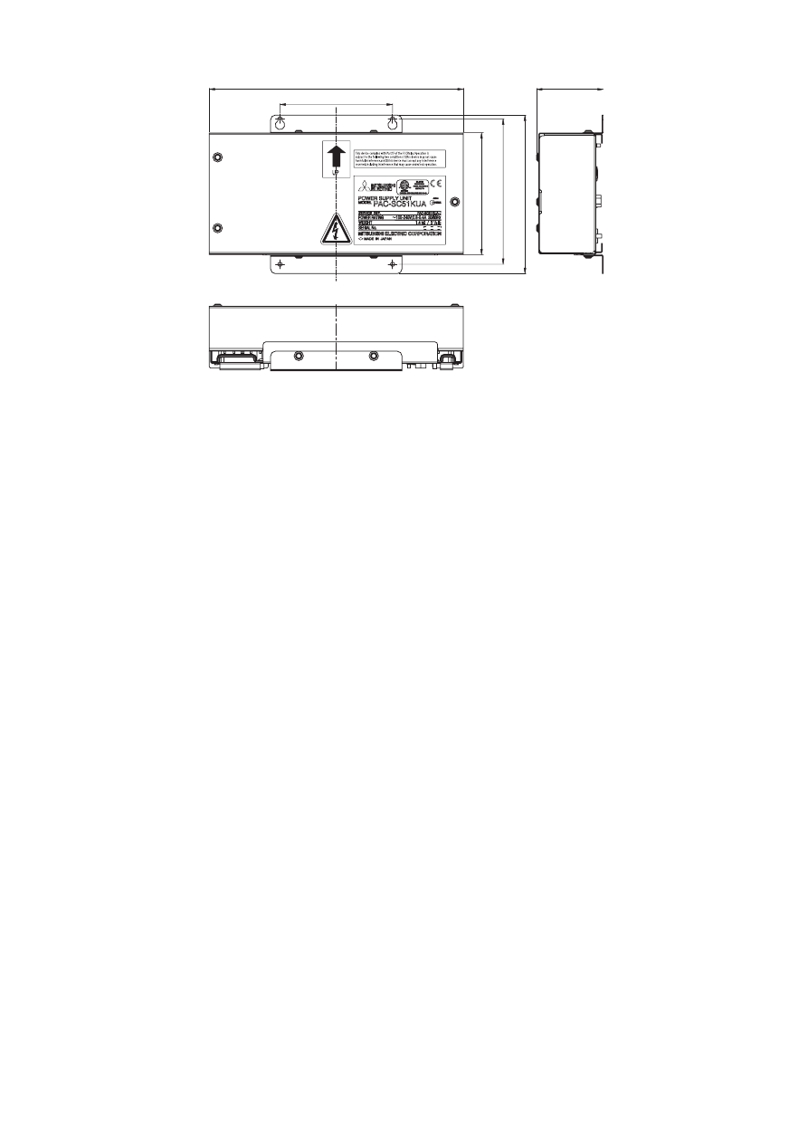
169 (H) × 271 (W) × 72 (D) mm (6-
11
/
16
[H] × 10-
11
/
16
[W] × 2-
7
/
8
[D] in.)
Weight
1.4 kg (3-
1
/
8
lbs.)
Installation Environment
In the control panel or in the mounting attachment A type (PAC-YG85KTB) (sold separately)
* This unit is designed for a business office or similar environment.
Centralized controller
Other system controllers
M-NET remote controller
AG-150A
G-50A
GB-50A
ON/OFF remote
controller
System remote controllers (SR)
Schedule timers (ST)
Group remote controllers (GR)
LOSSNAY remote
controller
Coefficient
0.5
-*¹
3
1
0.5
0.25
Centralized controller
Other system controllers
M-NET remote controller
AG-150A
G-50A
GB-50A
ON/OFF remote controller
System remote controllers (SR)
Schedule timers (ST)
Group remote controllers (GR)
LOSSNAY remote controller
1 unit*²
-*¹
1 unit*²
5 units
10 units
20 units
Total number of ON/OFF remote controllers (AN)
0
1
2
3
4
5
Total number of
System remote controllers (SR)
Schedule timers (ST)
Group remote controllers (GR)
0
V
V
V
V
V
1
V
V
V
V
V
2
V
V
V
V
3
V
V
V
V
4
V
V
V
5
V
V
V
6
V
V
7
V
V
8
V
9
V
- 3 -
3. External Dimensions
TB2,TB3
TB1
271 (10-11
/
16)
90 (3-9
/
16)
155
(6-
1
/
8)
130
(5-
1
/
8)
169
(6-
11
/
16
)
72 (2-7
/
8)
T
Unit: mm (in.)
- 4 -
3 Installation
1. Parts List
The parts listed below are included with the unit.
1
PAC-SC51KUA 1 unit
2
L-shaped mounting brackets 1 set
3
M4 screw (4 pieces for attaching the PAC-SC51KUA and the mounting bracket)
4
Installation Manual
2. Field-supplied Parts
Obtain the parts listed below before installing the unit.
*1 When installing the unit, use the switch having a contact separation of at least 3mm (
1
/
8
in) in each pole.
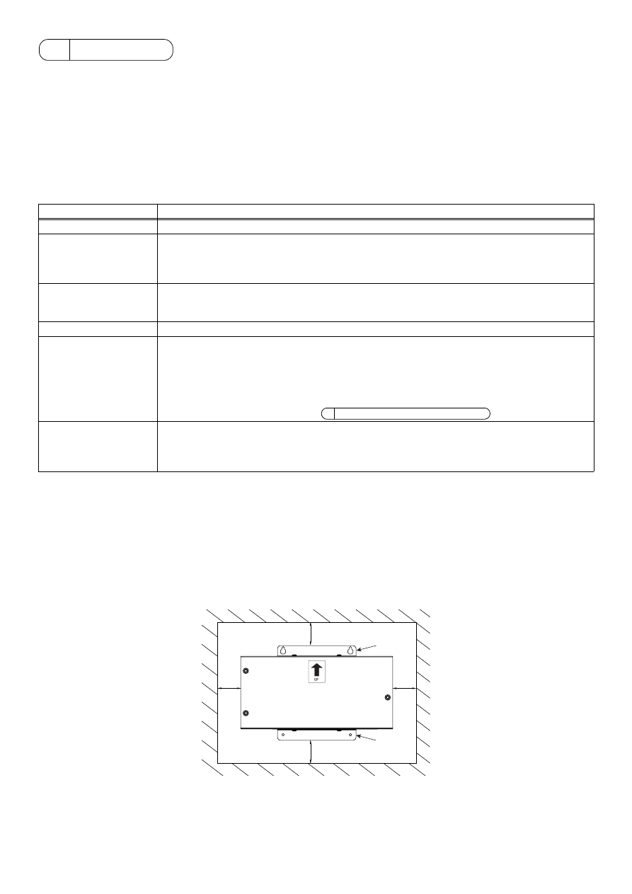
3. Installation area and direction
(1) To install the unit inside the control panel
Attach the mounting brackets to PAC-SC51KUA as shown in Fig. 3-1.
PAC-SC51KUA Power supply unit is not waterproof.
PAC-SC51KUA shall be installed in a control panel box (steel: thickness 1mm (
1
/
16
in.) or more).
Follow the installation requirements as shown in Fig. 3-1.
(Install in an area capable of withstanding a 1.4 kg (3-
1
/
8
lbs.) load.)
Only install the unit vertically as indicated by the arrow on the cover shown in Fig. 3-1.
(2) To install the unit inside the mounting attachment A type (PAC-YG85KTB) (sold separately).
PAC-SC51KUA can be installed inside the mounting attachment A type (PAC-YG85KTB) (sold separately).
Refer to the AG-150A Installation Manual for details.
Field-supplied Parts
Specification
Attachment screw
M4 screw × 4 pieces For wall mounting the unit.
Power cable/
Ground cable
Use sheathed vinyl cord or wire.
Wire type: Wire should not be lighter than standard PVC sheathed flexible cord IEC 60227
(designation 60227 IEC 53)
Wire size: 0.75mm² to 2mm² (AWG18 to 14)
Main power switch*¹
Breaker for wiring
• Local switch: Capacity 3A, Fuse 3A*
* Use B type fuse.
• Molded case breaker for wiring (NFB): Capacity 3A
Ground-fault interrupter
Level of earth leakage: 30mA, 0.1 sec or less
Transmission cable
Type: Sheathed vinyl cords or cable that complies with the following specifications or equivalent.
• CPEVS:
φ1.2mm to φ1.6mm
• CVVS: 1.25mm² to 2mm² (AWG16 to 14)
* CPEVS: PE insulated, PVC jacketed shielded communication cable
* CVVS: PVC insulated, PVC jacketed shielded control cable
PE: Polyethylene PVC: Polyvinyl chloride
Cable length: Please refer to section 5 M-NET Transmission Lines Length
DC power cable
DC power cable should comply with both local standards as well as the power requirements of the
unit.
Recommended type: 0.75mm² to 2mm² (AWG18 to 14)
Cable length: Within 50m (164 ft)
20 (13
/
16)
20 (13
/
16)
20 (13
/
16)
20 (13
/
16)
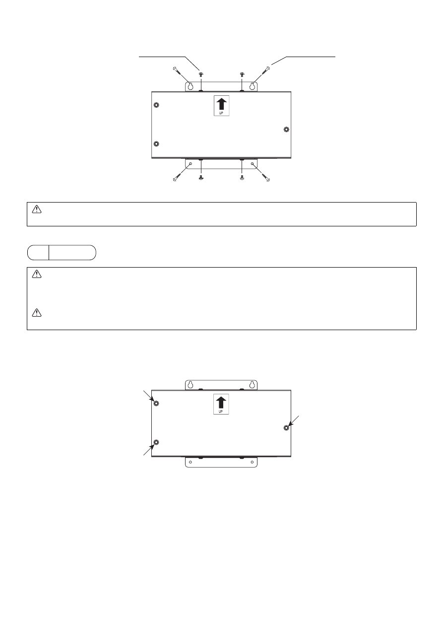
Mounting
brackets
Mounting
brackets
Unit: mm (in.)
Fig. 3-1
- 5 -
4. Unit installation
Attach the unit to the control panel box using M4 screws as shown in Fig. 3-2.
4 Wiring
1. Cover Removal and Installation
Remove the three mounting screws and the cover.
Attach the corner to the unit by tightening the three screws indicated in Figure 4-1.
CAUTION
The unit should be attached on all four corners to prevent it falling down.
WARNING
• All electric work must be performed according to local regulations.
Improper electrical work may result in electric shock or fire.
• Be sure to shut off the power source of this unit and all other connected units before wiring.
CAUTION
Do not connect the AC power line to the M-NET and POWER (24VDC) terminal blocks of this device; otherwise, the unit may fail.
Refer to the AG-150A Installation
Manual for instructions on how to
install the unit inside the mounting
attachment A type (PAC-YG85KTB)
(sold separately).
M4 (field-supplied)
Fig. 3-2
M4 (accessories)
Fig. 4-1
- 6 -
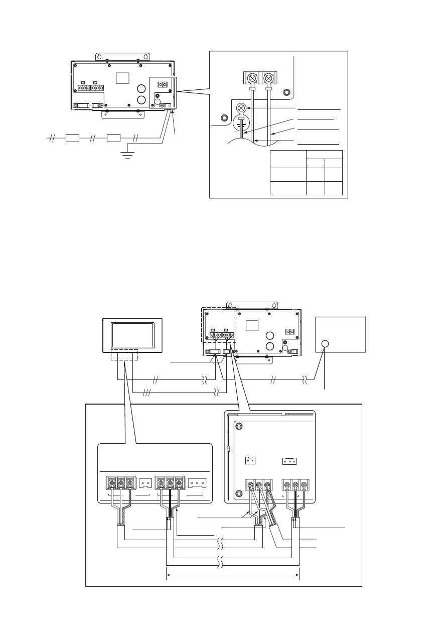
2. Power line
Wire the power and ground cables to L/L1, N/L2 and the ground cable terminals on TB1 as shown in Fig. 4-2.
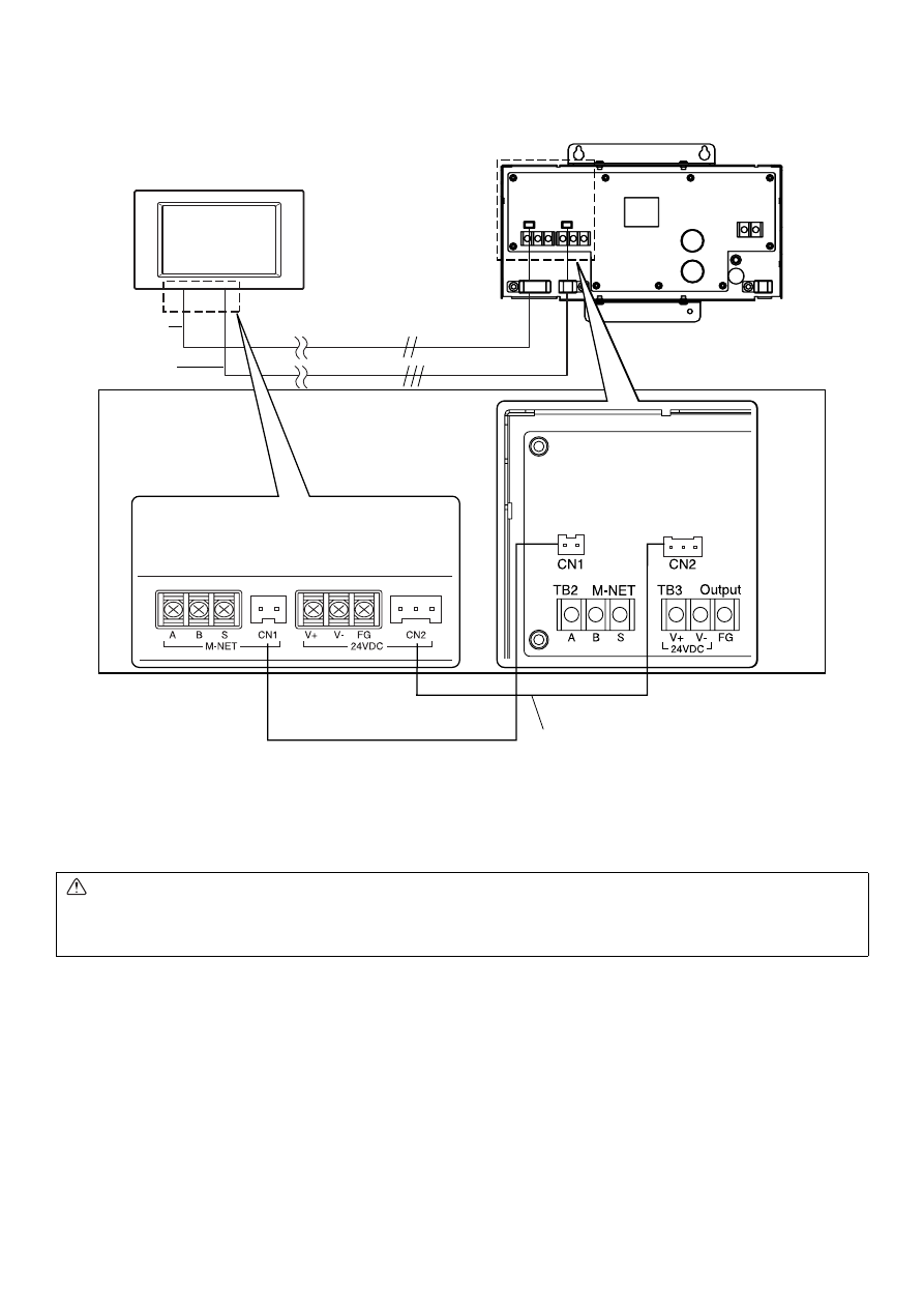
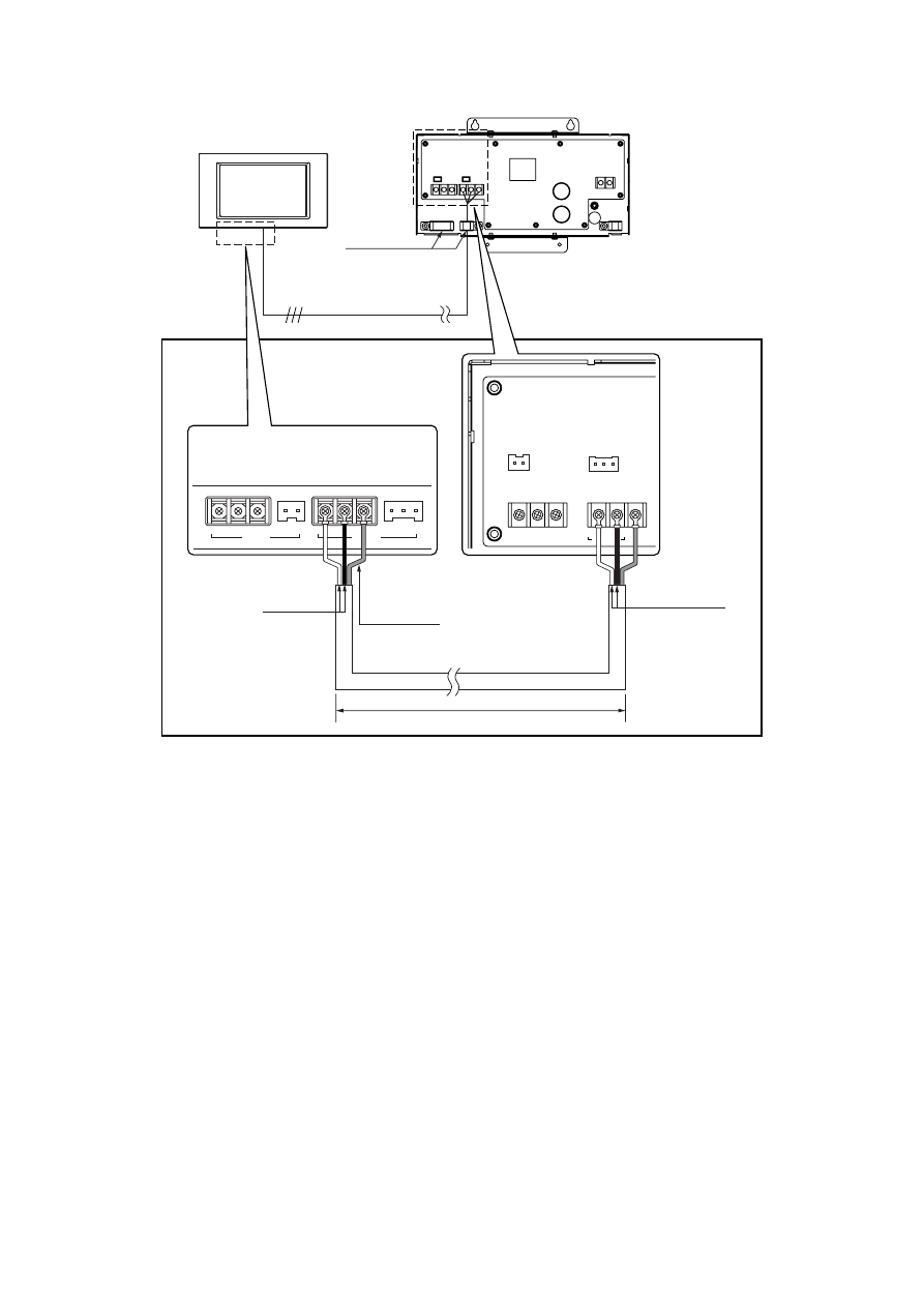
3. DC Power Supply and M-NET Transmission Line
3-1. When connecting to the centralized controller (AG-150A)
(1) Without the use of an expansion controller (PAC-YG50ECA)
(a) Connected via the terminal block
The DC power cable and M-NET transmission line connect as shown in Fig. 4-3. The DC power cable has a 24VDC and a GND
polarity. Connect it to the terminals in accordance with the polarity. Connect the M-NET transmission line to the A, B
(non-polarity), and S (shield) terminal block.
TB1
L/L1 N/L2
Applicable area
EU
US
L
L1
N
L2
Power cable
Ԙ
ԙ
㨪
100-240V
A
Breaker for
wiring
B
Ground-fault
interrupter
Power source
100-240VAC
50Hz/60Hz
B
A
Power cable
Ground
Ground cable
Attach the
power line
Power line terminal
Ground cable
Power cable 2
* Use L/N in EU.
* Use L1/L2 in the U.S.
* Use a ring terminal to connect to the terminal block.
Fig. 4-2
Ground terminal
Power cable 1
*1 Install ground-fault interrupter and breaker for wiring on
the power supply.
*2 Do not use anything other than a breaker and fuse with
the correct capacity. Using a fuse or wire of too large
capacity may cause malfunction or fire.
*3 Note : When installing the unit, use the switch having a
contact separation of at least 3mm (
1
/
8
in.) in each pole.
FG
V+
V-
A
B
S
CN1
CN2
24VDC
M-NET
A
B
S
V+ V- FG
M-NET
Output
CN1
CN2
TB2
TB3
24VDC
TB7
Power supply unit (PAC-SC51KUA)
Centralized controller
(AG-150A)
Outdoor unit
Cable Clamp
M-NET transmission line
(Centralized control line)
DC power supply line (24VDC) *Polarized
* Use a ring terminal to connect to the terminal block
Back of controller
DC power supply line
(Polarity)
Shield
M-NET transmission
A, B line (Non-Polarity)
50 m (164 ft) or less
Fig. 4-3
Function earthing
(ground) line
DC power supply
line (Polarity)
Power supply unit
- 7 -
(b) Connecting the connector
When installing the unit in the mounting attachment A type (PAC-YG85KTB) (sold separately), DC power cable and M-NET
transmission line can be connected with the connector as shown in the Fig. 4-4. Connectable to the connector using the cable
that is supplied with AG-150A (Refer to the Installation Manual that came with AG-150A for details.)
After connection for the each cable, fasten each cable with the cable fixture.
CAUTION
• Both of PAC-SC51KUA and Outdoor unit can supply DC power to the M-NET transmission line.
Set the outdoor unit central control system transmission line power supply to the factory setting CN41 (no supply). For further
details, refer to the outdoor unit installation manual. Failure to do so may cause unit malfunction or fire.
Power supply unit (PAC-SC51KUA)
Centralized controller
(AG-150A)
M-NET transmission
line (Centralized
controll line)
DC power supply line
(24VDC) *Polarized
M-NET transmission line (Centralized control line)
DC power supply line (24VDC)
*Polarized
Fig. 4-4
- 8 -
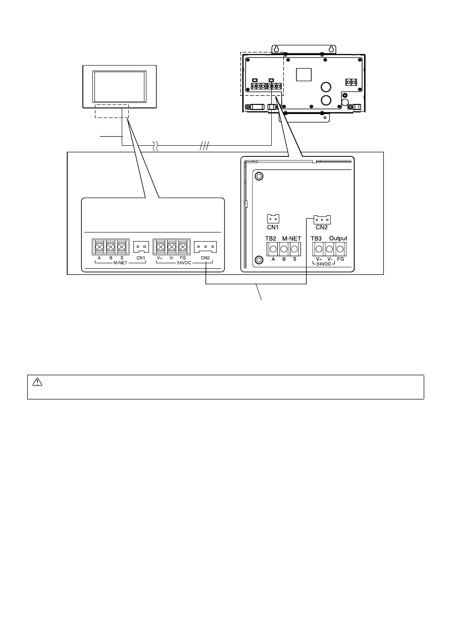
(2) With the use of an expansion controller (PAC-YG50ECA)
Only connect the DC power cable. (Use only TB3 or CN2.)
(a) Connected via the terminal block (TB3)
FG
V+
V-
A
B
S
CN1
CN2
24VDC
M-NET
A
B
S
V+ V- FG
M-NET
Output
CN1
CN2
TB2
TB3
24VDC
Power supply unit (PAC-SC51KUA)
Centralized controller
(AG-150A)
Cable Clamp
DC power supply line (24VDC) *Polarized
* Use a ring terminal to connect to the terminal block
Back of controller
DC power supply line
(Polarity)
50 m (164 ft) or less
Fig. 4-5
Function earthing
(ground) line
DC power supply
line (Polarity)
Power supply unit
- 9 -
(b) Connecting the connector (CN2)
After connection for the each cable, fasten each cable with the cable fixture.
3-2. When not connecting to the centralized controller (AG-150A)
Only use the M-NET output (TB2 or CN1).
CAUTION
• The 24 VDC power supply is for exclusive use with the centralized controller (AG-150A).
Power supply unit (PAC-SC51KUA)
Centralized controller
(AG-150A)
DC power supply line
(24VDC) *Polarized
DC power supply line (24VDC)
*Polarized
Fig. 4-6
- 10 -
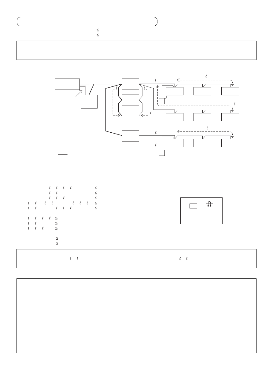
5 M-NET Transmission Lines Length
• Maximum length of M-NET transmission:
500m (1640 ft) *1
• Maximum power feeding length
:
200m (656 ft)
Example
1) Maximum length of M-NET transmission line:
1
L1+L2+L3+ 5+ 1+ 2 ( 3)
500m (1640 ft)
2
L1+L2+L3+ 5+ 4
500m (1640 ft)
3
L1+L2+L4+ 6+ 7 ( 8)
500m (1640 ft)
4
2 ( 3) + 1+ 5+L3+L4+ 6+ 7 ( 8)
500m (1640 ft)
5
4+ 5+L3+L4+ 6+ 7 ( 8)
500m (1640 ft)
2) Maximum power feeding length for the indoor control line:
1
5+ 1+ 2 ( 3) 200m (656 ft)
2
5+ 4
200m (656 ft)
3
6+ 7 ( 8)
200m (656 ft)
3) Maximum power feeding length for the centralized control line:
1
L1
200m (656 ft)*
2
L2 +L3 (L4)
200m (656 ft)
*The total length of DC power cable must not exceed 50m (164 ft).
NOTE
*
1: If the remote control cable exceeds 10m (32 ft), the additional length must be added to the total in order to avoid exceeding
the maximum length of the M-NET transmission specification.
NOTE
If the remote control cable ( 3, 8) does not exceed 10m (32 ft) in length, the length for 3,
8 may not need to be added to the
total length.
NOTE
This equipment has been tested and found to comply with the limits for a Class B digital device, pursuant to
Part 15 of the FCC Rules. These limits are designed to provide resonable protection against harmful interference
in a residential installation. This equipment generates, uses and can radiate radio frequency energy and,
if not installed and used in accordance with the instructions, may cause harmful interference to radio communications.
However, there is no quarantee that interference will not occur in a particular installation.
If this equipment does cause harmful interference to radio or television reception, which can be determined
by turning the equipment off and on, the user is encouraged to try to correct the interference by one or more
of the following measures:
-
Reorient or relocate the receiving antenna.
-
Increase the separation between the equipment and receiver.
-
Connect the equipment into an outlet on a circuit different from that to which the receiver is connected.
-
Consult the dealer or an experienced radio/TV technician for help.
Centralized
controller
Outdoor
unit*
Outdoor
unit*
Indoor
unit
Indoor
unit
Indoor
unit
Indoor
unit
Indoor
unit
Indoor
unit
Indoor
unit
Indoor
unit
Indoor
unit
M-NET remote controller
M-NET transmission line
(Centralized control line)
M-NET transmission line
(Indoor control line)
AG-150A
DC Power
supply
(24VDC)
Power
supply
unit
L1
L2
L4
L3
PAC-SC51KUA
1
3
M-NET remote controller
2
7
6
Length:
max. 50m (164 ft)
5
Outdoor
unit*
Outdoor
unit*
8
4
CN40
CN41
* To supply power to the M-NET line from PAC-SC51KUA,
connect the power jumper on outdoor unit to CN41.
Outdoor unit
ON
OFF

HEAD OFFICE: TOKYO BLDG. , 2-7-3, MARUNOUCHI, CHIYODA-KU, TOKYO 100-8310, JAPAN
Authorized representative in EU: MITSUBISHI ELECTRIC EUROPE B.V.
HARMAN HOUSE, 1 GEORGE STREET, UXBRIDGE, MIDDLESEX UB8 1QQ, U.K.
WT05372X03
Printed in Japan
Recycled Paper
Please be sure to put the contact address/telephone number on
this manual before handing it to the customer.
This product is designed and intended for use in the residential,
commercial and light-industrial environment.
The product at hand is
based on the following
EU regulations:
• Low Voltage Directive 2006/95/EC
• Electromagnetic Compatibility Directive,
2004/108/EC
Wyszukiwarka
Podobne podstrony:
IM PAC YG81TB WT05422X02 Apr 2009
IM PAC YG83UTB WT05420X01 Apr 2009
IM PAC IF011B E IF012B E BH79D099H02 GB 09 2009
IM PAC SE51CRB WT03594X05 GB Aug 2009
Kwasy karboksylowe Apr 2009(1)
IM PAC KE07DME WT05243X01 2007
IM PAC SC36NA E(WT04936X01) GB
0300122810 Yale University Press One State Two States Resolving the Israel Palestine Conflict Apr 20
IM PAC SE51CRA WT02699X01 GB 2005
IM PAC SA1ME E RG79V563H01 2007
IM PAC YG66DCA WT04977X01 EN 2007
IM PAC YG63MCA WT04975X01 EN 2007
IM PAC SE55RA E WT02925x01 pd
IM PAC YG60MCA WT04973X01 EN 2007
IM PAC AK31 51BC BG79U439K08 Sep 2010
IM PAC AH125 140 250M H WT04980X02 GB 2007
IM MAC 399IF E SG79Y416H05 Sep 2009
więcej podobnych podstron