MITSUBISHI ELECTRIC
Building Air Conditioning Control System
Remote ON/OFF Adaptor
PAC-SE55RA-E
Instruction Manual
This product is a wiring component that connects an external circuit to the indoor unit when the air conditioner is being operated by an external cir-
cuit (locally procured). Variations of the connection method with the external circuit will provide different types of operating configurations.
Example: Timer operation, remote control operation, others.
For your safety, first be sure to read “ 1 Safety Precautions “ described below thoroughly and then install the Remote ON/OFF Adaptor PAC-
SE55RA-E correctly.
This symbol denotes what could lead to serious injury or death if your misuse the PAC-SE55RA-E.
This symbol denotes what could lead to a personal injury or damage to your property if you misuse the PAC-SE55RA-E.
●
The following two symbols are used to denote dangers that may be caused by incorrect use and their degree:
●
After reading this instruction manual, keep it in a place where the final user can see it anytime he or she wants to it.
When someone moves, repairs or uses the PAC-SE55RA-E, make sure that this manual is forwarded to the final user.
1 Safety Precautions
.
WARNING
.
CAUTION
.
WARNING
Ask your dealer or technical representative to install the unit.
Any deficiency caused by your own installation may result in an elec-
tric shock or fire.
Ensure that installation work is done correctly following this
instruction manual.
Any deficiency caused by installation may result in an electric shock
or fire.
.
CAUTION
Do not install in any place exposed to flammable gas leakage.
Flammable gases accumulated around the body of PAC-SE55RA-E
may cause an explosion.
Do not use in any special environment.
Using in any place exposed to oil (including machine oil), steam and
sulfuric gas may deteriorate the performance significantly or give
damage to the component parts.
Do not install in any steamy place such a bathroom or kitchen.
Avoid any place where moisture is condensed into dew.
Doing so may cause an electric shock or a malfunction.
Wire so that it does not receive any tension.
Tension may cause wire breakage, heating or fire.
Do not wash with water.
Doing so may cause an electric shock or a malfunction.
Do not install in any place where acidic or alkaline solution or spe-
cial spray are often used.
Doing so may cause an electric shock or malfunction.
Do not install in any place at a temperature of more than 40
:
:
or
less than 0
:
:
or exposed to direct sunlight.
Stop the operation if any malfunction occurs.
If malfunction occures (burning smell, etc.) stop the operation and turn
off the power supply. Contact the your dealer or technical representa-
tive immediate. If the controller continues to operate after a malfunction
occurs, this may cause damage, electric shock or fire.
Firmly connect the wiring using the specified cables.
Carefully check that the cables do not exert any force on the ter-
minals.
Improper wiring connections may produce heat and possibly a fire.
Never modify or repair the PAC-SE55RA-E by yourself.
Any deficiency caused by your modification or repair may result in an
electric shock or fire.
Consult with your dealer about repairs.
All electrical work must be performed by a licensed technician,
according to local regulations and the instructions given in this
manual.
Any lack of electric circuit or any deficiency caused by installation may
result in an electric shock or fire.
Do not move and re-install the PAC-SE55RA-E yourself.
Any deficiency caused by installation may result in an electric shock or
fire.
Ask your distributor or special vendor for moving and installation.
WT02925X01
2 Confirming the Supplied Parts
1. Check that the box contains one adaptor for remote ON/OFF adaptor (2m) in addition to this manual.
2. All parts other than the remote ON/OFF adaptor (PAC-SE55RA-E) are procured locally.
➀
External timer : No voltage contact output timer (with separate circuits for power supply and switch).
➁
Switch : Single pole, single action switch.
.
Caution Select a part with contacts for extremely low amperage.
DC 5V or 12V is used at the contact points for the timer and switch so there is a load
of only approximately 1mA. Improper switch selection could cause improper operation.
➂
Transit relay : This is used when installing the wiring in accordance with "6. Wiring Restrictions."
➃
Electric wire : The length of the electrical wiring for the remote ON/OFF adaptor is 2 meters.
To extend this length, use sheathed vinyl cord or cable.
Electric wire type: CVV, CVS, CPEV or equivalent.
Wire size: 0.5 mm
2
to 1.25 mm
2
Keep wire extensions to within 10 meters.
Do not turn on the main power until installation has been complet-
ed.
Fail to do so may cause an electric shock or fire.
Note : Please keep LVD. LVD;Low Voltage Directive (EC Directive of Europe)
Apply some countermeasure for wiring and relay not to be touched
from outside.
➀
Wiring should be covered by the insulation tube.
➁
Use relay with EU regulation.
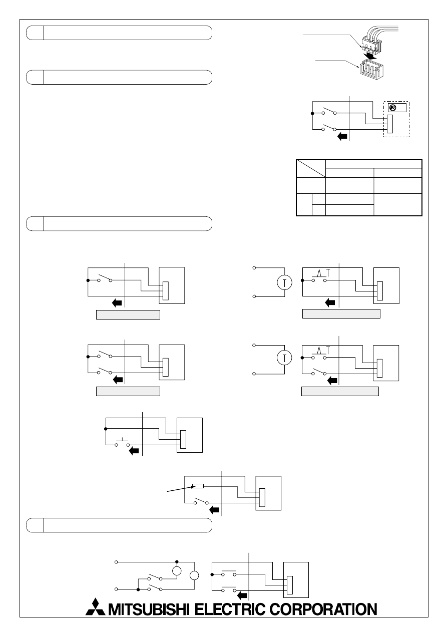
3 Connecting to the Indoor Unit
1. Connect to the connector CN32 on the indoor controller board.
2. Press the connector for the remote ON/OFF adaptor into the CN32 connector.
The connector can only be connected in one direction only. Do not force the connection.
4 Locally Procured Wiring
With the remote ON/OFF adaptor, variations of connection method with the locally
installed circuit will provide different types of operating configurations.
Example: External timer operation, remote control operation
1. Basic Connection Method
SW1 - Operating switch
Performs operation/stopping of indoor unit.
SW2 - Selecting switch
For selecting whether the operation/stopping is to be performed by external circuit
or remote control.*
* Also includes system controller (central controller).
2. Switch Settings (Refer to table at right for details.)
5 Examples of Usage
6 Wiring Restrictions
For remote operation
CN32
Orange
Red
Brown
Local wiring
For remote timer operation
CN32
Orange
Red
Brown
Local wiring
Indoor controller board
For remote operation
CN32
Orange
Red
Brown
Local wiring
CN32
Orange
Red
Brown
Local wiring
SW1
SW1
Power supply for
external timer
For remote timer operation
CN32
Orange
Red
Brown
Local wiring
Power supply for
external timer
SW2
SW2
CN32
Orange
Red
Brown
Local wiring
SW2
SW2
Since this is not used, be sure to
completely wrap with insulation tape
If SW2 is on, operation cannot be performed by
the remote controller.
If SW2 is off, operation is permited.
Use a momentary switch (a switch that is turned on manually and
turns off automatically) for SW2.
Press SW2 (for 1 second or more) and the operation starts. After
this, the remote controller can be used for operations.
In either case, there is a 5 to 6 second delay from the time when the operating command is sent until the unit operates.
1. To perform operation/stopping by only remote operation or external timer and to prohibit operation/stopping by the remote
controller, use the following circuits.
2. To perform operation/stopping by remote operation or external timer and allow operation/stopping by the remote
controller, use the following circuits.
3. To start operation by remote operation and then freely use remote controller, use the following circuit.
4. To permit/prohibit the use of the remote controller by an external circuit.
Indoor controller board
Indoor controller board
Indoor controller board
Indoor controller board
Indoor controller board
SW2
ON
OFF
SW1
ON
OFF
Remote
controller
Cannot perform
operation/stopping
Can perform
operation/stopping
Operation
Stopping
Cannot perform
operation/stopping
Indoor controller
board
CN32
Orange
Red
Brown
Local wiring
SW1
SW2
ELV
SW2 - If on.
• Operation/stopping cannot be controlled from
remote controller.
Other operations (such as temperature settings
and changing fan speed) can be performed.
• Operation/stopping can be performed by SW1.
SW2 - If off.
• Operations can be performed
from remote controller.
• Operation/stopping cannot be
performed by SW1.
2
3
Remote ON/OFF adaptor
CN32 connector
CN32
Orange
Red
Brown
Local wiring
Power supply
X2
X1
SW2
SW1
X2
X1
Indoor controller board
Keep the length of wire from the circuit board of the indoor unit within 10 meters. Excessive length could cause improper opera-
tion.
Use a transit relay when extending wiring such as remote wiring.
Wyszukiwarka
Podobne podstrony:
IM PAC SF40RM E WT02926X01
IM PAC KE07DME WT05243X01 2007
IM PAC SC36NA E(WT04936X01) GB
IM PAC IF011B E IF012B E BH79D099H02 GB 09 2009
IM PAC SE51CRA WT02699X01 GB 2005
IM PAC SA1ME E RG79V563H01 2007
IM PAC YG66DCA WT04977X01 EN 2007
IM PAC YG81TB WT05422X02 Apr 2009
IM PAC YG63MCA WT04975X01 EN 2007
IM PAC YG83UTB WT05420X01 Apr 2009
IM PAC YG60MCA WT04973X01 EN 2007
IM PAC AK31 51BC BG79U439K08 Sep 2010
IM PAC AH125 140 250M H WT04980X02 GB 2007
IM PAC YT51CRA WT03594X02 GB 2005
IM PAC SA88HA E WT02522X01 pl
IM PAC IF011B E RG79D377H01 pl
IM PAC KE03DM F WT03396X01
IM PAC SE51CRB WT03594X05 GB Aug 2009
IM PAC SH83 84 85 86DM E RG79V973H02 Nov 2010
więcej podobnych podstron