
Mitsubishi Electric Air Conditioner Network System
DIDO controller
PAC-YG66DCA
Installation/Instruction Manual
Before using the DIDO controller, please read this installation/instruction manual carefully to ensure proper operation.
Keep this installation/instruction manual for future reference.
Contents
Page
1.
Safety Precautions.............................................. 1
2.
Device Capabilities ............................................. 1
3.
Confirmation of Parts .......................................... 2
4.
Specifications...................................................... 2
4-1.
Product Specifications ....................... 2
4-2.
External View ..................................... 3
5.
Example of System Configuration....................... 3
6.
Installation Method.............................................. 4
6-1.
Parts to be Procured Locally.............. 4
6-2.
Installation Procedure ........................ 4
7.
Wiring Method..................................................... 6
7-1.
Names of Parts .................................. 6
7-2.
Connecting the Power Line and
M-NET Transmission Line ................. 7
7-3.
Connecting the Signal Lines .............. 7
7-3-1. Standard Terminals
(Channels 1 and 2) ............................ 8
(1) Inputs ................................................. 8
(a) Non-voltage a Contact Inputs....... 8
(2) Outputs .............................................. 8
(a) Non-voltage Relay Contact
Outputs......................................... 8
(b) Transistor Outputs
(Open Collector) ........................... 9
7-3-2. Expansion Connectors
(Channels 3 to 6) ............................. 10
(1) Expansion Inputs/Outputs................ 10
8.
Initial Setting Procedure.................................... 11
9.
Switch List......................................................... 12
10.
Display Content................................................. 13
10-1.
Display Content List ......................... 13
10-2.
Communication Error Status
Display ............................................. 14
11.
Test Run ........................................................... 14
1
• Before using the device, thoroughly read the following safety precautions and use as directed.
• Hazards and levels of danger that can occur due to incorrect handling are classified by the following symbols.
• After reading this manual, keep this manual for future reference. When the device is reinstalled or repaired, give this
manual to those who provide these services. When the user changes, make sure that the new user receives this manual.
This device can be used in combination with a system controller to operate/stop general-purpose equipment, as well as to
monitor the operating status and error status.
Furthermore, this device is equipped with two sets (channels 1 and 2) of standard terminals and four sets of expansion
connectors as the input/output terminals.
In addition to the above, this device also features an interlock function that interlocks M-NET devices for indoor units, etc. set
in advance and performs settings such as temperature control and operation/stoppage using the status of contact terminals.
1
Safety Precautions
Warning
Incorrect handling can result in death, serious injury, etc.
Caution
Incorrect handling can result in injury or damage to the building or its contents.
WARNING
CAUTION
Ask your dealer or a qualified technician to install the device.
Improper installation by the user may result in electric shock or fire.
Properly install the device on a surface that can withstand the
weight of the device.
Device installed on an unstable surface may fall and cause injury.
Only use specified cables. Securely connect each cable so
that the terminals do not carry the weight of the cable.
Improperly connected or fixed cables or short-circuited cables may
produce heat and/or result in fire.
Do not make any modifications or alternations to the device.
Modifications or improper repair may result in electric shock or fire.
Consult your dealer for repair.
Properly install the device according to the instructions in this
manual.
Improper installation may result in electric shock or fire.
Have all electrical work performed by an authorized
electrician according to the local regulations and instructions
in this manual.
Power supply circuit capacity shortage or improper installation may
result in electric shock or fire. Ask your dealer or a specialist when
performing an electrical work.
Do not move or reinstall the device by yourself.
Improper installation may result in electric shock or fire. Consult
your dealer or a specialist when moving or reinstalling the device.
Do not install the device where a flammable gas leak may
occur.
If a flammable gas leaks and piles up around the device, it may be
ignited and/or explode.
Do not use the device in an unusual environment.
If the device is installed where a large amount of oil (including machine
oil), steam or sulfidizing gas is present, this environment may lead the
device to a remarkable drop in performance or damage its parts.
Do not install the device where a large amount of steam rises,
such as in the bathroom or kitchen.
Avoid installing this device where dew condensation occurs. If the
device is installed in such places, it may result in electric shock or
malfunctions.
Do not install the device where acidic or alkaline solutions or
chemical sprays are used frequently.
Doing so may lead to electric shock or malfunctions.
When installing the device in a hospital, communication station, or similar place, provide sufficient protection against noise.
An inverter equipment, private power generator, high-frequency medical equipment or radio communication equipment may interfere with the
normal operation of this device. On the other hand, the device may affect such equipment by creating noise that disturbs medical treatment or
image broadcasting.
Do not put tension on the power supply wires.
If tension is put on the wires, they may break and result in
excessive heat and/or fire.
Do not immerse the device in water.
Doing so may lead to electric shock or malfunctions.
Do not install the device where the temperature may become
more than 40°C [104°F] or less than 0°C [32°F] or it will be
subjected to direct sunlight.
If the device is installed in such place, it may result in deformation
or malfunctions.
Use standard products with the proper current capacity.
The use of non-standard wires may result in current leak,
excessive heat, and/or fire.
Do not touch the main board with hands or tools. Prevent dust
from forming on the board.
Doing so may result in fire or malfunctions.
Do not apply an AC power source. The maximum applied
voltage for the device is 24 VDC.
Using the incorrect voltage may result in device failure, ignition,
and/or fire.
2
Device Capabilities
Caution: Usage Restrictions
• We take no responsibility for compensation for damages caused by reasons not attributable to us, for opportunities lost as a
result of a failure of this device or an electrical power failure on the customer or any third party site, for damages caused by
special circumstances, regardless of whether we can predict them or not, for secondary damages, for accidental damages, or
for damages to objects other than this device.
We also take no responsibility for compensation for damages caused by the customer's work, including, but not limited to,
replacement work, readjustment of machinery and equipment on the local site, and startup and trial operation.
• Do not use this device for disaster prevention control and security control.
(In particular, do not use this device in life critical applications.)
• It is recommended to provide a circuit such as an external switch capable of turning operation on/off from general-purpose
equipment in case operation of the general-purpose equipment becomes no longer possible because of a failure of the DIDO
controller or a peripheral part.
2
• Confirm that the box contains the following parts.
* In addition to the parts mentioned above, other parts need to be procured locally in order to operate this device. Furthermore, other Mitsubishi optional
parts may be required depending on how the device is to be used.
For details, refer to "6 Installation Method".
4-1. Product Specifications
*1: For details, refer to "6-1 Parts to be Procured Locally".
*2: Supply electric power from a power unit for the transmission line or an outdoor unit. Furthermore, the power consumption factor of the M-NET circuitry
of this device is "1/4" (equivalent to one ME Remote Controller).
*3: Non-voltage Relay contact or transistor is available for output. Only one can be used at a time.
*4: ( ) is in the case of a pulse.
*5: The output is open collector type. Power must be supplied from an external power source to the output circuit of this device.
*6: Power is supplied from this device to the external contacts.
*7: Power must be supplied from an external power source.
*8: Interlock control is performed from the Maintenance Tool. For details, refer to the instruction manual for the Maintenance Tool.
3
Confirmation of Parts
Number
Part Name
Quantity
1
DIDO controller
1
2
Installation/instruction manual (this document)
1
4
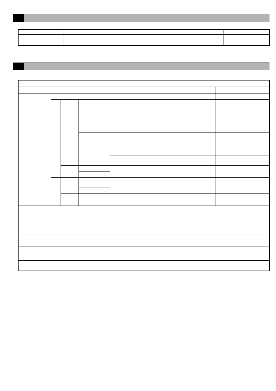
Specifications
Item
Rating and Specification
Power Supply
24 VDC±10%: 5 W (*1)
Screw terminal block (M3)
Interface
M-NET communication
17 to 30 VDC (*2)
Screw terminal block (M3)
Output
(*3)
ON/OFF,
(ON)
(*4)
Non-voltage Relay contact
(2)
Applied load
MAX: 24 VDC, 5 W
MIN: 5 VDC, 2 mW
* AC loads cannot be
connected.
Screw terminal block
(M3.5)
Transistor (2)
24 VDC 40 mA or less
(*5)
Screwless terminal block
(OFF)
(*4)
Non-voltage Relay contact
(2)
Applied load
MAX: 24 VDC, 5 W
MIN: 5 VDC, 2 mW
* AC loads cannot be
connected.
Screw terminal block
(M3.5)
Transistor (2)
24 VDC 40 mA or less
(*5)
Screwless terminal block
Input
ON/OFF
Non-voltage a contact
(2 each)
24 VDC 1 mA or less
(*6)
Screwless terminal block
Error/Normal
Output
(*3)
ON/OFF, (ON)
(*4)
Transistor (4 each)
24 VDC 40 mA or less
(*5)
9 pin connector
(OFF) (*4)
Input
ON/OFF
24 VDC input (4 each)
24 VDC 1 mA or less
(*7)
9 pin connector
Error/Normal
Interlock
Function
Interlock M-NET devices and output contacts according to status of input contacts. (*8)
Environment
Conditions
Temperature
Operating temperature range 0 to 40°C [32°F to 104°F]
Storage temperature range
-20 to 60°C [-4°F to 140°F]
Humidity
30 to 90%RH (no condensation)
Dimensions
200 (W) × 120 (H) × 45 (D) mm / 7
7
/
8
(W) × 4
3
/
4
(H) × 1
25
/
32
(D) in
Weight
0.6 kg / 1 3/8 lb
Current Time
Backup during
Power Failure
If the power is cut, the internal capacitor will keep counting the current time normally for approximately one week.
(The internal capacitor takes approximately a day to charge. Replacement of a battery is not necessary.)
Installation
Environment
Inside a control panel (indoors)
* Use this product in a hotel, a business office environment or similar environment.
Standard
Expansion
3
4-2. External View
200 (7
7
/
8
)
111 (4
3
/
8
)
45 (1
25
/
32
)
107.6
( 4
1
/
4
)
15
(
19
/
32
)
11
0
(
4
11
/
32
)
26
( 1
1
/
32
)
120
( 4
3
/
4
)
26
( 1
1
/
32
)
150 (5
29
/
32
)
26 (1
1
/
32
)
83.5 (3
5
/
16
)
27 (1
3
/
32
)
52 (2
1
/
16
)
46.5 (1
27
/
32
)
4.5
(
3
/
16
)
[ 24 VDC Power Supply]
N623
DIDO
PAC-YG66DCA
MODEL
DIDO controller
SERVICE REF. PAC-
INPUT
WEIGHT
SERIAL No.
MADE IN JAPAN
YG66MCA-J
VOLTAGE
DC24V;0.2A
0.6 kg / 1 /
3 8
lb
PAC-YG66DCA
[ Output LEDs ]
ON/OFF
(ON)
(OFF) ON/OFF
(ON)
(OFF)
Ch2
Ch1
harmful interference, and (2)this device must accept any interference
received, including interference that may cause undesired operation.
subject to the following two conditions: (1)this device may not cause
This device complies with Part15 of the FCC Rules.Operation is
controller
[ INPUT ]
[ Expansion
ON/OFF
Error
Error
ON/OFF
Ch2
Ch1
I/O ]
Ch5,Ch6
Ch3,Ch4
[ OUTPUT ] Non-voltage Contact Output
ON/OFF,(ON)
ON/OFF,(ON)
(OFF)
(OFF)
ON/OFF,(ON)
(OFF)
ON/OFF,(ON)
[ Junction Terminal ]
[ OUTPUT ] Transistor Output
(OFF)
Ch2
Ch1
Ch2
Ch1
24 VDC
9
(
3
/
8
)
Unit: mm (in)
5
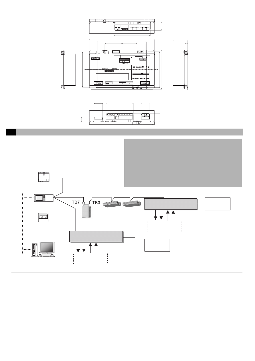
Example of System Configuration
Note:
• For the shield ground of the M-NET centralized control line, use single-point grounding at the power unit for the transmission
line.
However, when supplying electric power to the M-NET centralized control line from the R410A series outdoor unit without using
a power supply unit for the transmission line, use single-point grounding at the TB7 of that outdoor unit.
Furthermore, when connecting this device to the M-NET indoor control line, use grounding at the TB3 for each outdoor unit
system.
• If this device is connected to the M-NET indoor control line and the outdoor unit is down because, for example, the power supply
is interrupted for servicing or there is a failure, the DIDO controller cannot be controlled from the system controller.
• Controlling the system remote controller, ON/OFF remote controller, and schedule timer is only possible with channel 1 of a
standard terminal.
• When G(B)-50A is connected, monitoring control can only be performed from G(B)-50A Web or TG-2000A. Monitoring control
cannot be performed from the system remote controller, ON/OFF remote controller or schedule timer.
(c)
M-NET
M-NET
LAN
(a) (b)
(d)
(a) (b)
(c) (d)
(a) ON/OFF, (ON) output
(b) (OFF) output
(c) ON/OFF input
(d) Error/Normal input
Standard: Terminal block (for 2 units)
Expansion: Connectors (for 4 units)
Total: 6 units
<Restrictions>
Maximum of 50 units (50 channels) per G(B)-50A
However, the number of units that can be connected to a G(B)-50A is
up to 50 including the number of contacts used on this device, an
indoor unit, Lossnay unit, etc.
Centralized control line
Indoor control line
DIDO controller
G-50A or GB-50A
or
System remote controller,
ON/OFF remote controller,
Schedule timer
G(B)-50A Web or
TG-2000A
DIDO controller
Ventilation fan,
lighting, etc.
× up to 6 units
Ventilation fan,
lighting, etc.
* This figure omits the power supply line and only shows the transmission line.
24 VDC
Power supply
24 VDC
Power supply
Power supply unit
PAC-SC50KUA
× up to 6 units
City Multi
4
6-1. Parts to be Procured Locally
Prepare the following parts to install this device.
[Parts to be Purchased Separately]
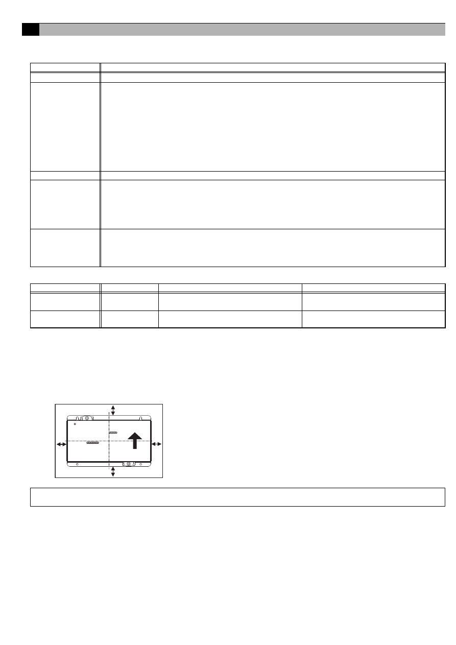
6-2. Installation Procedure
The DIDO controller PAC-YG66DCA does not have a waterproof structure.
Be sure to install the DIDO controller inside a control panel that is located indoors.
Prepare a control panel capable of storing this device such as the one shown in the figure. (Install the device in a control
panel strong enough to withstand a weight of 0.6 kg [1
3
/
8
lb].)
This device can be installed flat or vertically. Clear the space shown below when installing.
6
Installation Method
Required Part
Specification
Unit fixing screws
M4 screw × 4
Power supply for this
unit
Power source: 24 VDC±10% 0.2 A (Minimum loading), SELV circuit, power line with grounding terminal
Ripple noise: Lower than 200 mVp-p
Compatible specification
Authorized or CE marked products
Subject to regulations: - IEC60950 (or EN60950)
- CISPR22/24 (or EN55022/24)
- IEC61000-3-2/3-3 (or EN61000-3-2/3-3)
When using transistor output (including extension output) for the 24 VDC output of this device, increase the
capacity to match the number used.
• 1 set used: 0.3 ADC (Minimum) • 2 sets used: 0.4 ADC (Minimum) • 3 sets used: 0.5 ADC (Minimum)
• 4 sets used: 0.6 ADC (Minimum) • 5 sets used: 0.7 ADC (Minimum) • 6 sets used: 0.8 ADC (Minimum)
* The increase of the power supply capacity is 0.1 ADC for every set.
Power line
Use a sheathed vinyl cord or cable. At least 0.75 mm² (AWG18)
M-NET transmission
line
Type of the cable: Sheathed vinyl cords or cable which comply with the following specifications or equivalent.
• CPEV
Φ1.2 mm to Φ1.6 mm • CVVS 1.25 mm² to 2 mm² (AWG 16 to 14)
* CPEV: PE insulated PVC jacketed shielded communication cable
* CVVS: PVC insulated PVC jacketed shielded control cable
PE: Polyethylene PVC: Polyvinyl choloride
Power needs to be supplied to the M-NET circuitry of this device. Use an outdoor unit or a separately purchased
power supply unit for the transmission line.
Signal lines
Use electric wire of an appropriate size for the terminal block of this device.
Electric wire size ···· (1) Solid wire:
Φ0.65 mm (AWG21) – Φ1.2 mm (AWG16)
(2) Stranded wire: 0.75 mm² (AWG18) – 1.25 mm² (AWG16)
Single strand: At least
Φ0.18 mm
To use an expansion input/output, use a separately purchased external input/output adapter.
Name
Model
Application
Remark
Power supply unit
PAC-SC50KUA
Power supply to the M-NET transmission line This is not required when power is to be
supplied from an outdoor unit.
External I/O adapter
PAC-YG10HA
Connection adapter for using an expansion
input/output
This is required when an expansion input/
output is used.
Note: The space shown above does not include space for peripherals. Additionally, the amount of space necessary varies according to
the functions that are used and the wiring method. Secure enough space appropriate for the type of installation.
100
(
3
15
/
16)
100
(
3
15
/
16)
100
(
3
15
/
16)
100
(
3
15
/
16)
Size of the device: 200 (W) × 120 (H) × 45 (D) mm/
7
7
/
8
(W) × 4
3
/
4
(H) × 1
25
/
32
(D) in
Unit: mm (in)
5
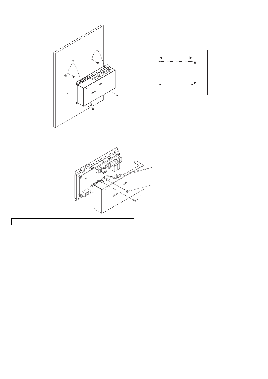
(1) Fix the top of this unit to the control panel at two points by loosely tightening the screws (M4) that were procured locally.
Fix the bottom in place with two screws and then tighten all four of the screws.
(2) To remove the cover, as shown in the figure, remove the two screws for fixing the cover in place and then remove the cover by
unhooking the upper hook section from the lower case. To attach the cover, hook the upper hook section on the lower case and then
fix the cover in place with the two screws that were removed.
Note: Two hooks are located on the upper section of the cover.
Screw pitch
Unit: mm (in)
110
(
4
11
/32)
150
(
5
29
/32)
Hooks
Screws for fixing
the cover
6
(3) Refer to "7 Wiring Method" and connect the wires for the power line, M-NET transmission line, and input/output signal lines.
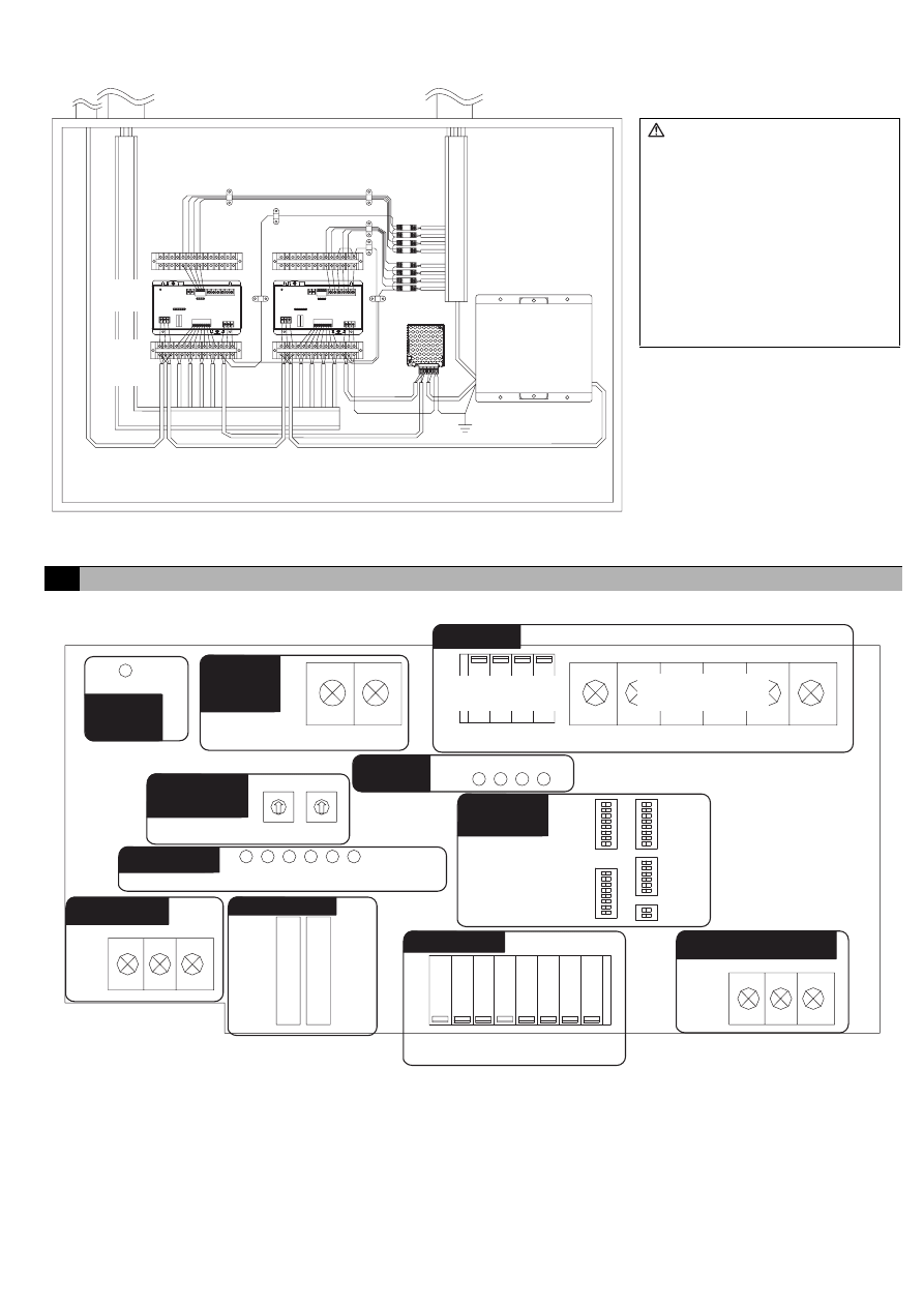
7-1. Names of Parts
N
FG
L
-V
+V
PAC-SC50KUA
M-NET
Diagram Image (Installed within a Control Panel)
* The wiring in the diagram has been
simplified.
M-NET
Input
Power line/Output
DIDO
controller
24 VDC
Power source
Relay
Junction
terminal
block
Caution:
• Perform wiring so that the
terminal block is not strained.
If strained, use a wire guide or
junction terminal to alleviate the
stress on the terminal block.
• Do not connect the wires
directly from the top of the
control panel to the terminal
block.
Moisture may enter this device
along the wiring and cause
electric shock or fire.
7
Wiring Method
CN16
CN04
CN10
/ 11 / 19
/ 20
CN40
CN06 / 05 / 08 / 03
CN17
CN12
CN14
LED 11/ 12/ 13/ 14/ 15/ 16
SW03
SW01
SW08
SW02
SW09
SW06
SW07
LED05/ 04/ 03/ 02
A / B / S
V+ / V- / FG
LED17
Non-voltage
Contact Output
Transistor Output
(open collector)
(CPU power on)
10s
1s
Output
Junction
Terminal
(24 VDC)
Output
LEDs
M-NET
Address
Input
24 VDC Power Supply
Expansion I/O
Status LEDs
M-NET
M-NET
Power on
Function
Settings
7
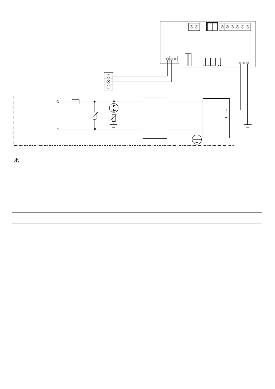
7-2. Connecting the Power Line and M-NET Transmission Line
7-3. Connecting the Signal Lines
• Separately procure the relay, power supply for the relay, terminal block, and cable locally.
• The maximum wire length is 100 m. However, since the use of long wires makes the device susceptible to noise, using
wires shorter than 10 m is recommended.
• Connect another relay within 10 m from DIDO controller to extend the input line.
CN16
CN17
A/B/S
V+/V-/FG
S
FG
M-NET
S / B /
A
(M1)
(M2)
U
U
R
Tightening torque for terminal screws: 1 N·m
Connect the device to a power supply unit (PAC-SC50KUA) for
the transmission line or an outdoor unit (either a centralized
control line or indoor control line can be connected).
* Only the M-NET circuitry of this device receives the power from the
M-NET transmission line. The power consumption factor is "1/4"
(equivalent to one ME Remote Controller).
Figure 7-1 Example of Connecting the Power Line and M-NET Transmission Line
DIDO controller
Circuit Onsite
(example)
Fuse
Varistor
Arrester
Noise
Filter
24 VDC
Power
source
AC Power Line
Varistor
* Functional
ground
Caution:
• Use a power line and M-NET transmission line that satisfy the specifications described in "6-1 Parts to Procured Locally".
• Attach a circuit comprising the following components to the supply primary side of the 24 VDC power supply.
(1) Varistor, (2) Arrester, (3) Noise filter, (4) Fuse
• It is important to pay attention to the polarity when connecting to the 24 VDC power supply terminal block.
Connecting the positive and negative in the reverse order will cause a failure.
• Fix the power line and M-NET transmission line in place on the outside to ensure that the terminal block is not affected by any
external force.
Not securely connecting and fixing the wires in place may cause heat generation and fire.
• Make sure that the copper wiring is not short-circuiting the plates (cover, lower case) or neighboring wires.
Cover the shielded line of the M-NET transmission line with materials such as vinyl tape and prevent short-circuiting with the plates.
Note: If this device is connected to an M-NET indoor control line and the outdoor unit is down because, for example, the power supply
is interrupted for servicing or there is a failure, the DIDO controller cannot be controlled from the system controller.
8
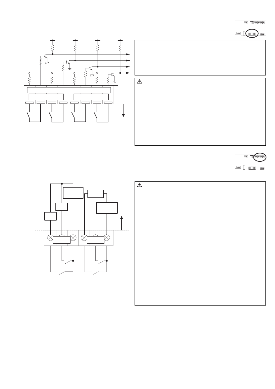
7-3-1. Standard Terminals (Channels 1 and 2)
(1) Inputs
(a) Non-voltage a Contact Inputs
* To use these, various settings need to be configured. Refer to "8 Initial Setting Procedure".
(2) Outputs
* Non-voltage Relay contact or transistor is available for output. Only one can be used at a time.
(a) Non-voltage Relay Contact Outputs
* To use these, various settings need to be configured. Refer to "8 Initial Setting Procedure".
Ch1
Ch2
/
11
/ 19
/
20
CN 10
+
ON/OFF
ON/OFF
+
+
+
Note:
• Connect the operate/stop (ON/OFF) inputs so that closing the
contact operates (ON) the device and opening the contact
stops (OFF) the device.
• The error/normal inputs of channels 1 and 2 can be switched
between a contact and b contact. For details, refer to "9
Switch List".
Caution:
• The polarity of the input terminals is important, so be sure to
match the polarity when using contacts that have polarity.
• Select a contact with a minimum applicable load of 1 mADC
or less.
• Supply 24 VDC 1 mA from the positive terminal to the external
contacts.
• Strip 12±1 mm (15/32 ±1/32 in) of the wire coating and insert
firmly into the terminal.
• Make sure that the copper wiring is not short-circuiting the
plates (cover, lower case) or neighboring wires.
• Perform wiring so that the terminal block is not strained.
If strained, use a wire guide or junction terminal to alleviate
the stress on the terminal block.
Error/
Normal
Error/
Normal
Line Onsite
24 VDC
CN04
Ch1
Ch2
V2
Y1
Y1
X1
(OFF)
ON/OFF, (ON)
ON/OFF, (ON)
(OFF)
Caution:
• To use X1 and Y1 relay, obtain one that satisfies the following
specifications.
Operating coil
[Applied load]
MAX: 24 VDC, 5 W (Built-in diode)
MIN: 5 VDC, 2 mW (Built-in diode)
*1 AC loads cannot be connected.
*2 Provide a power supply (V1, V2) that matches the load
and relay to be used.
• To drive a direct load, use ones within the following.
[Applied load]
MAX: 24 VDC, 5 W
MIN: 5 VDC, 2 mW
* AC loads cannot be connected.
• Make sure that the copper wiring is not short-circuiting the
plates (cover, lower case) or neighboring wires.
• Perform wiring so that the terminal block is not strained.
If strained, use a wire guide or junction terminal to alleviate
the stress on the terminal block.
• Do not connect the wires directly from the top of the control
panel to the terminal block.
Moisture may enter this device along the wiring and cause
electric shock or fire.
( ) is in the case of a pulse.
Line
Onsite
Load
Tightening torque for terminal screws: 1 N·m
Power supply
V1 (DC)
Power supply
V2 (DC)
9
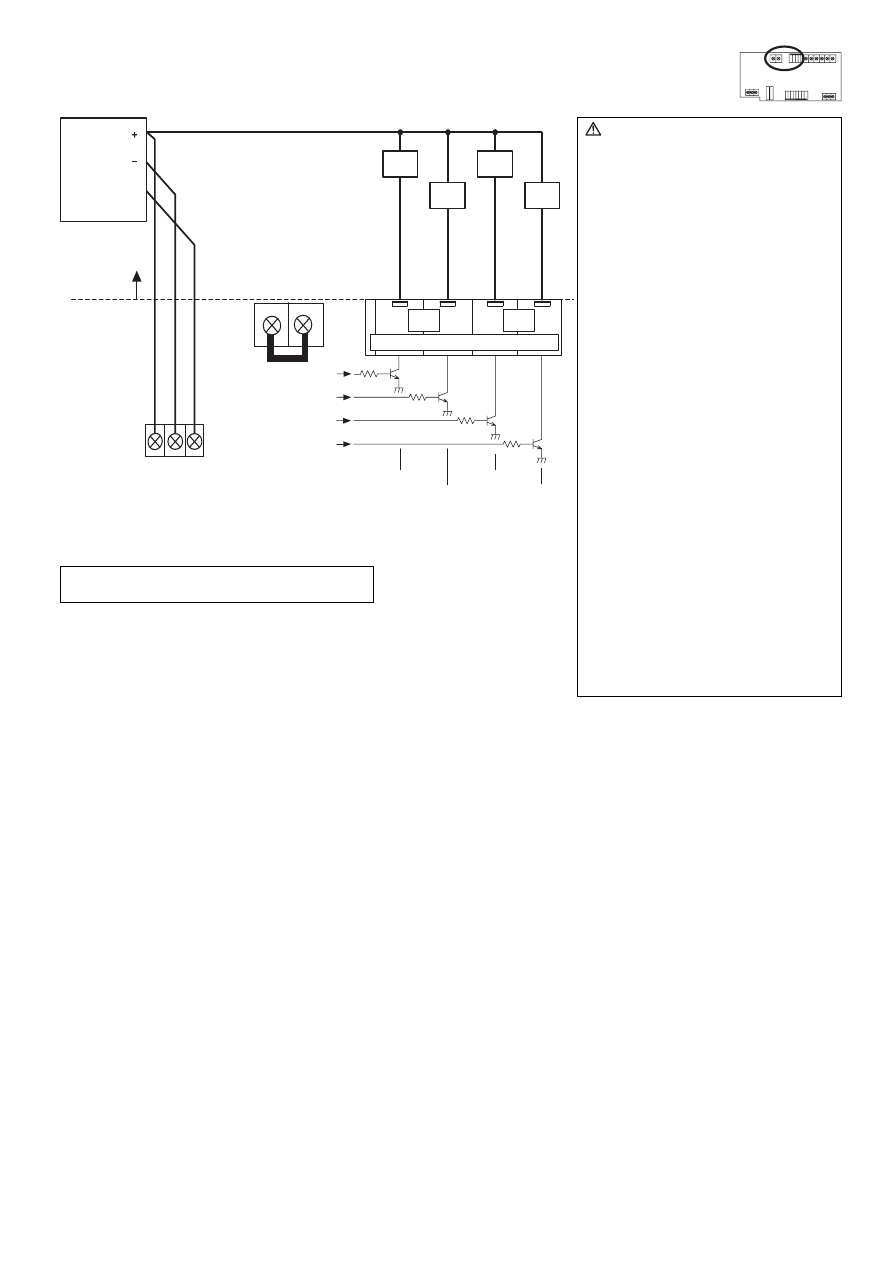
(b) Transistor Outputs (Open Collector)
* To use these, various settings need to be configured. Refer to "8 Initial Setting Procedure".
X2
Y2
X1
Y1
Ch2
Ch1
FG
CN16
V+/ V-/ FG
CN40
CN06
ON/OFF,
(ON)
ON/OFF,
(ON)
(OFF)
(OFF)
05
/
/
/
08
03
Caution:
• When X1, X2, Y1 and Y2 relays are
used, select ones that satisfy the
following specifications.
Operating coil
Rated voltage: 24 VDC (Built-in
diode)
Power consumption: 0.9 W or less
(*1) Be sure to use the ones with
the voltages rated above.
Exceeding the rated voltage
may affect the ON/OFF of
other outputs.
(*2) When using a separate
power supply for this device,
connect GND of the power
supply to V- of CN16 of the
terminal block of this device.
(*3) Use a relay with a
withstanding voltage of at
least 2000 VAC between the
coil and contact.
Otherwise, there is the
likelihood of an electric shock
or fire.
• Strip 12±1 mm (15/32 ±1/32 in) of the
wire coating and insert firmly into the
terminal.
• Make sure that the copper wiring is
not short-circuiting the plates (cover,
lower case) or neighboring wires.
• Perform wiring so that the terminal
block is not strained.
If strained, use a wire guide or
junction terminal to alleviate the
stress on the terminal block.
• Do not connect the wires directly from
the top of the control panel to the
terminal block.
Moisture may enter this device along
the wiring and cause electric shock or
fire.
( ) is in the case of a pulse.
24 VDC Power source
Line Onsite
24 VDC
Power
source
Note: The junction terminal CN40 is provided.
Use them as relay terminals if necessary.
Tightening torque for terminal screws: 1 N·m
10
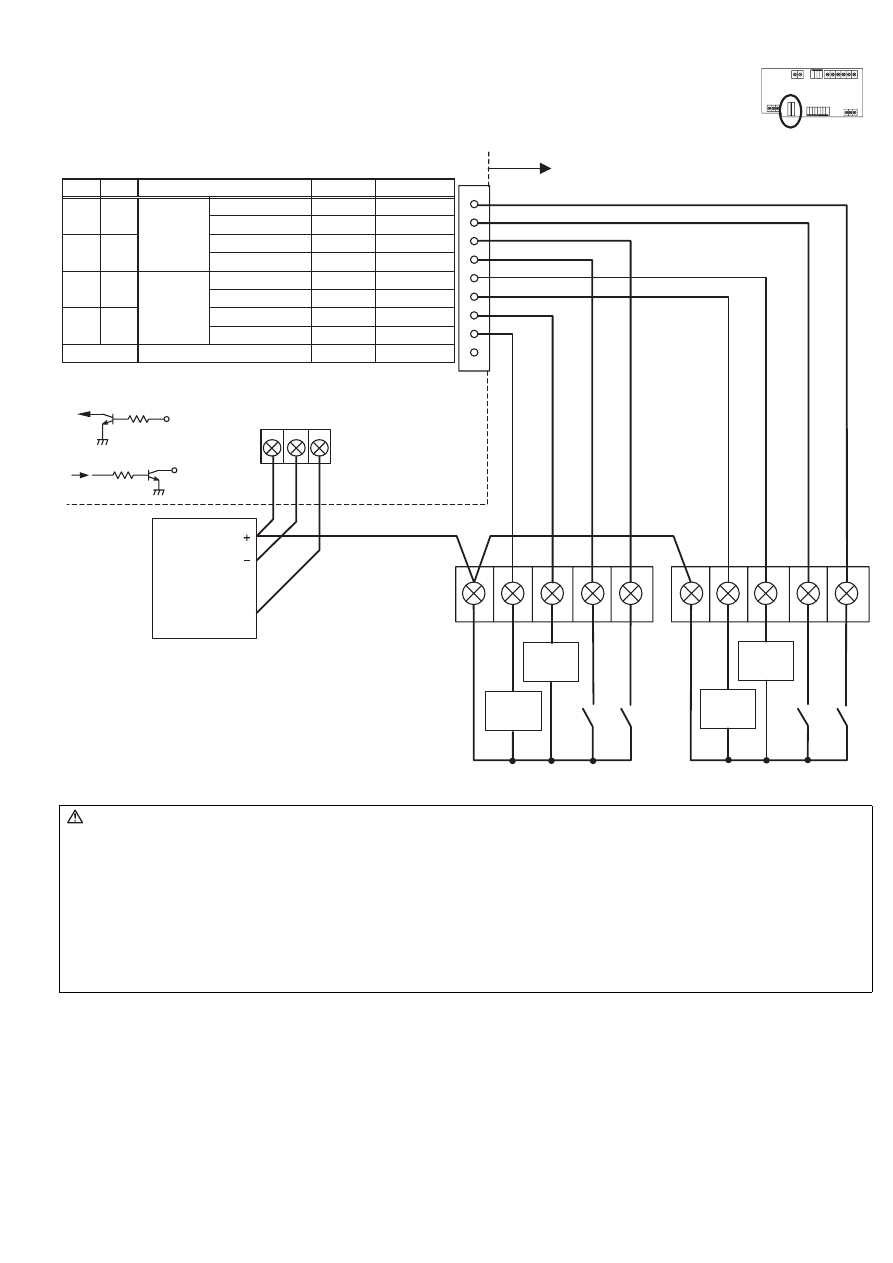
7-3-2. Expansion Connectors (Channels 3 to 6)
(1) Expansion Inputs/Outputs
* Purchase an optional external input/output adapter (model: PAC-YG10HA) when using expansion inputs/
outputs.
* To use these, various settings need to be configured. Refer to "8 Initial Setting Procedure".
PAC -YG10HA
X2
Y2
X4
Y3
X3
Y1
X1
Y4
CN16
V + / V- / FG
FG
CN14
(CN12)
CN14
Ch3
Ch5
Ch4
Ch6
Ch3
Ch5
Ch4
Ch6
CN12
ON/OFF
ON/OFF
ON/OFF, (ON)
(OFF)
(OFF)
ON/OFF, (ON)
3
5
7
8
-
9
9
1
1
2
4
6
Brown
Purple
Orange
Yellow
Blue
Gray
INPUT
OUTPUT
( ) is in the case of a pulse.
Terminal Block
Input
Output
24 VDC
Power
source
Circuit example
24 VDC Power Source
Error/Normal
Error/Normal
Unused
Function
Pin No.
Green
Red
Black
Lead Wire
Line Onsite
Caution:
• When using X1, X2, X3, X4, Y1, Y2, Y3 and Y4 relays, select ones that satisfy the following specifications.
Operating coil
Rated voltage: 24 VDC (Built-in diode)
Power consumption: 0.9 W or less
(*1) Be sure to use the ones with the voltages rated above. Exceeding the rated voltage may affect the ON/OFF of other outputs.
(*2) When using a separate power supply for this device, connect GND of the power supply to V– of CN16 of the terminal block
of this device.
(*3) Use a relay with a withstanding voltage of at least 2000 VAC between the coil and contact.
Otherwise, there is the likelihood of an electric shock or fire.
• Select a contact with a minimum applicable load of 1 mADC or less for the input contact.
11
After completing the procedures described in "6 Installation Method" and "7 Wiring Method," set the initial settings in
accordance with the procedure described below.
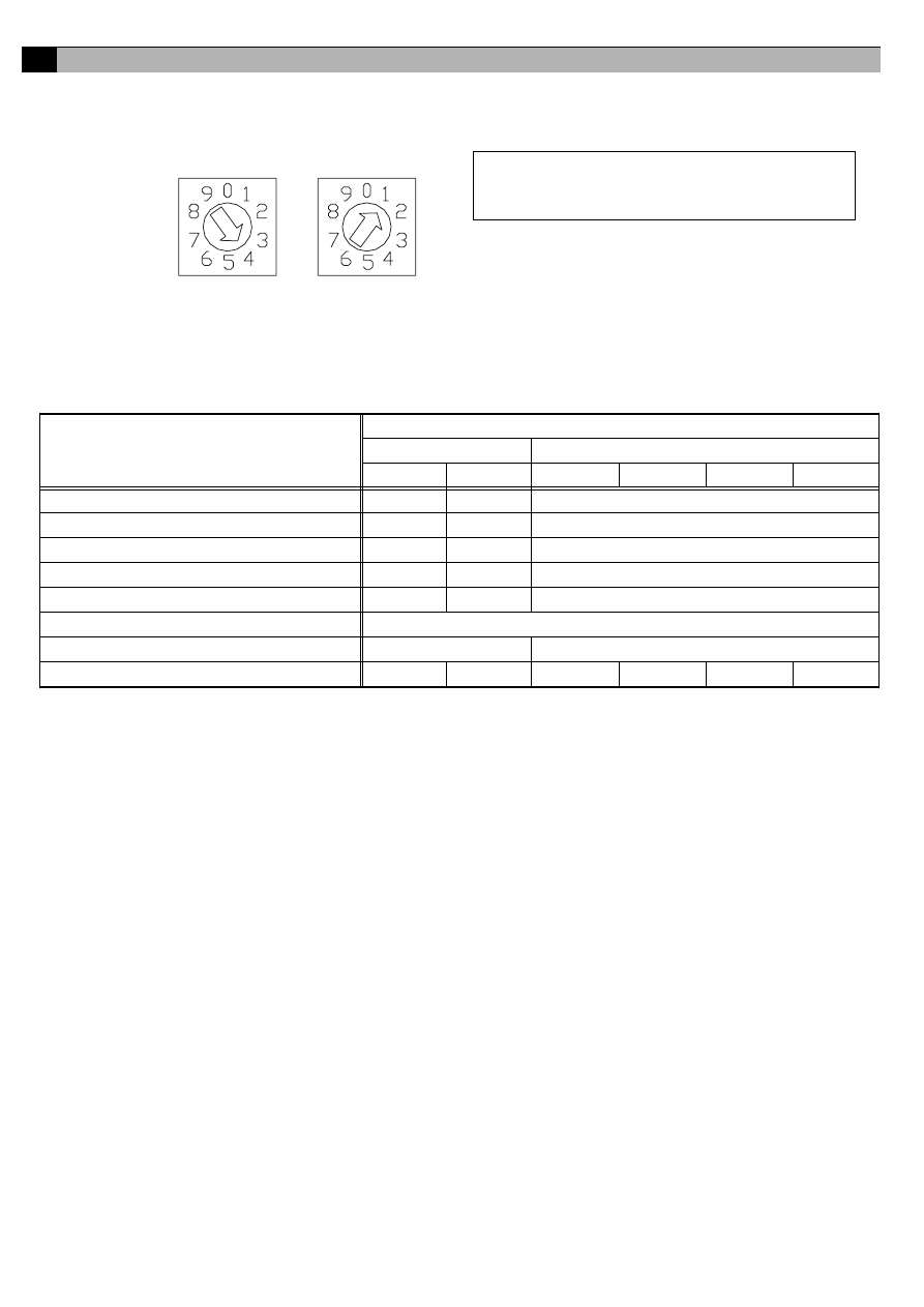
(1) M-NET address settings
(2) Use the dip switches to select functions.
Select the function required for each input/output channel to be used.
The switch assignment for each channel is shown below. Configure each of the settings while referring to "9 Switch List".
(3) Turn on the power of this device.
Verify that the LED16 (CPU power on) and LED17 (M-NET power on) are lit.
(4) Set the group settings so that this device is a target for control from the system controllers.
Set the group settings (contact numbers to use (channel)) in the system controllers (G(B)-50A, TG-2000A, system remote controller,
schedule timer, and ON/OFF remote controller) and then start up this device.
* With the system remote controller, schedule timer, and ON/OFF remote controller, group settings can only be configured for
channel 1.
(5) Set the time.
Set the current time from a system controller (G(B)-50A, TG-2000A, system remote controller, or schedule timer) or a Maintenance
Tool.
(6) To use the interlock control function, perform settings from the Maintenance Tool.
Perform settings such as interlocking criteria for this device with the Maintenance Tool.
For details on setting procedures, refer to the instruction manual for the Maintenance Tool.
8
Initial Setting Procedure
Setting
Channel Used
Standard
Expansion
Ch1
Ch2
Ch3
Ch4
Ch5
Ch6
Emergency stop command enable setting
SW01-1
SW02-1
SW03-1 (The setting is common to channels 3 to 6)
Error input logic setting
SW01-2
SW02-2
SW03-2 (The setting is common to channels 3 to 6)
Error interlock stop output setting
SW01-3
SW02-3
SW03-3 (The setting is common to channels 3 to 6)
Output operation setting for power failure recovery
SW01-4
SW02-4
SW03-4 (The setting is common to channels 3 to 6)
Output signal setting
SW01-5
SW02-5
SW03-5 (The setting is common to channels 3 to 6)
Selection of status display mode
SW03-6, SW03-7
Error display is cancelled (for 10 seconds).
SW03-8
–
Error input usage setting
SW08-1
SW08-2
SW08-3
SW08-4
SW08-5
SW08-6
SW06
SW07
Note:
• An address from 01 to 50 can be set.
• Set an address that is not the same as that of
another unit.
The address is set to "01" at factory shipment.
In the case of address "41"
10s
1s
12
Set the dip switches for function selection according to the system to be used.
At the time of shipment, all dip switches are set to OFF and the M-NET address is set to 01.
The settings of SW03-1 to 5 are common to expansion input/output channels 3 to 6.
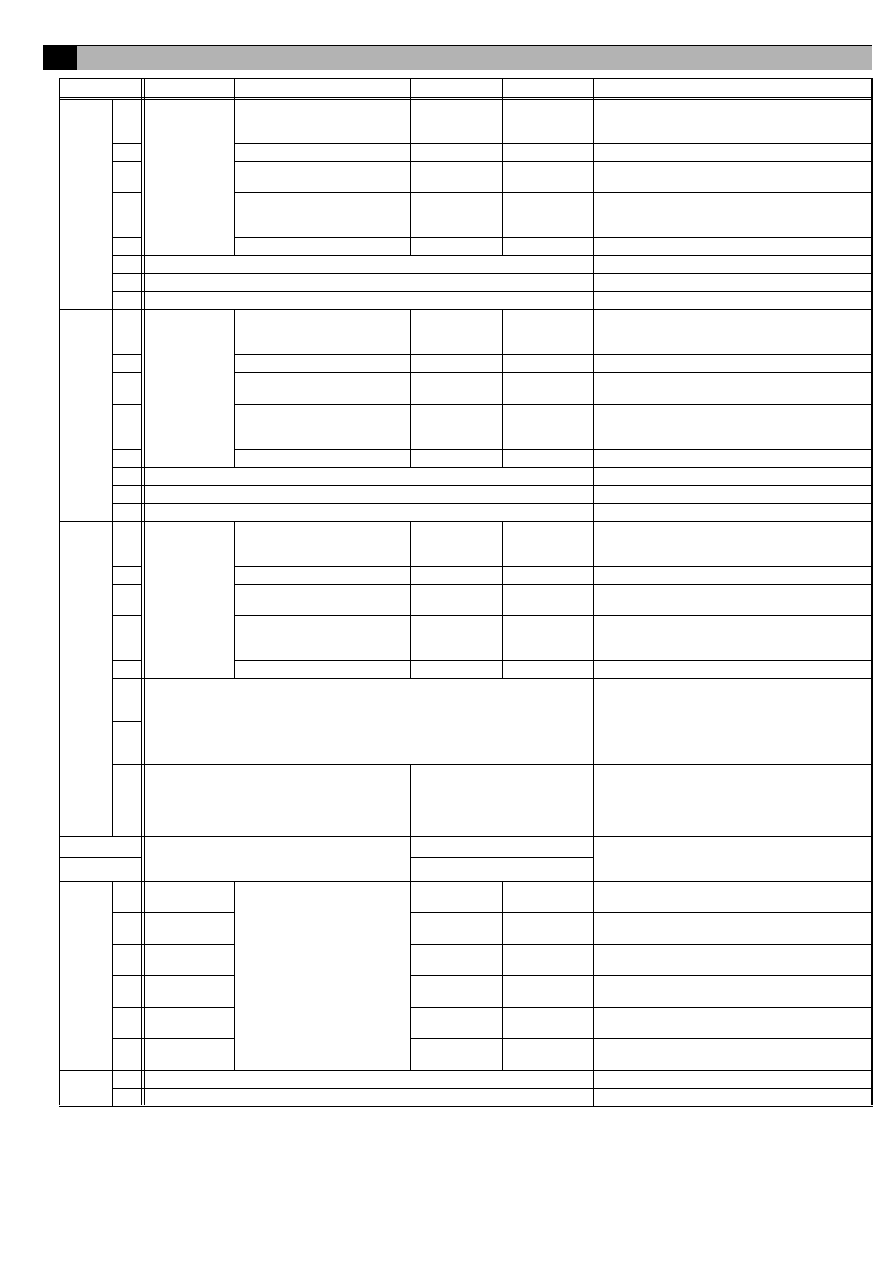
9
Switch List
Switch
Channel
Function Setting
OFF
ON
Remark
SW01
1
Channel 1
(standard)
Emergency stop command
enable setting
Disabled
Enabled
Select the output operation for when an emergency
stop command is received from a system
controller.
2
Error input logic setting
a contact
b contact
–
3
Error interlock stop output
setting
No
Yes
Select whether to interlock and stop output for error
input.
4
Output operation setting for
power failure recovery
Stop
Recover to
state prior to
power failure
Select the output operation for when there is a
recovery from a power failure.
5
Output method setting
Level output
Pulse output
–
6
Unused
Set to OFF
7
Unused
Set to OFF
8
Unused
Set to OFF
SW02
1
Channel 2
(standard)
Emergency stop command
enable setting
Disabled
Enabled
Select the output operation for when an emergency
stop command is received from a system
controller.
2
Error input logic setting
a contact
b contact
–
3
Error interlock stop output
setting
No
Yes
Select whether to interlock and stop output for error
input.
4
Output operation setting for
power failure recovery
Stop
Recover to
state prior to
power failure
Select the output operation for when there is a
recovery from a power failure.
5
Output method setting
Level output
Pulse output
–
6
Unused
Set to OFF
7
Unused
Set to OFF
8
Unused
Set to OFF
SW03
1
Channel 3 to 6
(standard)
Emergency stop command
enable setting
Disabled
Enabled
Select the output operation for when an emergency
stop command is received from a system
controller.
2
Error input logic setting
a contact
b contact
–
3
Error interlock stop output
setting
No
Yes
Select whether to interlock and stop output for error
input.
4
Output operation setting for
power failure recovery
Stop
Recover to
state prior to
power failure
Select the output operation for when there is a
recovery from a power failure.
5
Output signal setting
Level output
Pulse output
–
6
Selection of status display mode:
SW03-6,
SW03-7
(1) Normal display (input status or error status
of channels 1 and 2):
OFF
OFF
(2) Operation input status display of channels 3 to 6:
OFF
ON
(3) Operation output status display of channels 3 to 6:
ON
OFF
(4) Error input status display of channels 3 to 6:
ON
ON
Select the display mode for the status display LED
mode.
7
8
Error display is cancelled (for 10 seconds).
Change the switch to ON once
and then return it to OFF.
Only enabled while communication error status is
displayed.
* The communication error status display is
masked for 10 seconds and the status set with
SW03-6 and 7 is displayed.
SW06
M-NET address
(Address 10s) 0 to 9 (decimal)
An address from 01 to 50 can be set.
Set an address that is not the same as that of
another unit.
SW07
(Address 1s) 0 to 9 (decimal)
SW08
1
Channel 1
(standard)
Error input usage setting
No
Yes
Select whether to use error/normal input for
channel 1.
2
Channel 2
(standard)
No
Yes
Select whether to use error/normal input for
channel 2.
3
Channel 3
(expansion)
No
Yes
Select whether to use error/normal input for
channel 3.
4
Channel 4
(expansion)
No
Yes
Select whether to use error/normal input for
channel 4.
5
Channel 5
(expansion)
No
Yes
Select whether to use error/normal input for
channel 5.
6
Channel 6
(expansion)
No
Yes
Select whether to use error/normal input for
channel 6.
SW09
1
Unused
Set to OFF
2
Unused
Set to OFF
13
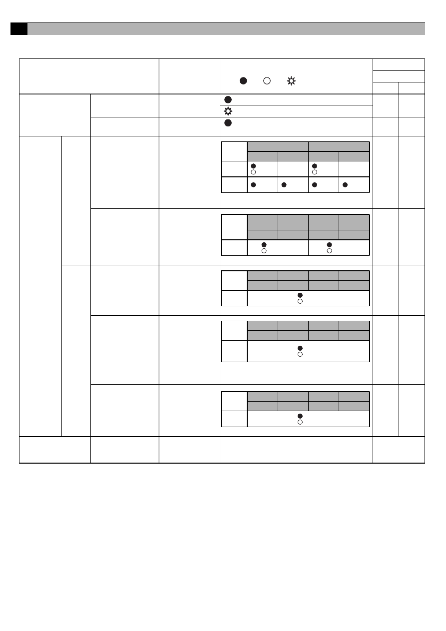
The LEDs of this device indicate the operation output status, operation input status, and error status of this device.
10-1. Display Content List
*1: If LED11 flashes quickly three times in any of the display states, it is an indication that an error input has been detected on one of channels 3 to 6. To
confirm the details, turn ON both of SW03-6 and 7 and select to "(3) Error Input Status Display of Channels 3 to 6".
*2: If a communication error occurs in any of the display states, switch to "Communication Error Status Display". Changing SW03-8 from ON to OFF masks
the "Communication Error Status Display" for 10 seconds so that the input/output status display set with SW03-6 and 7 can be confirmed.
10
Display Content
Display Item
Display LED
Content
Note :On, :Off, :Flashing
Condition
Switch
03-6
03-7
Power supply status
(1) Power supply to
CPU
LED16
(CPU power on)
: Lights when the CPU is energized.
–
–
: Flashes during M-NET communication.
(2) Power supply to
M-NET circuit
LED17
(M-NET power on)
: Lights when the M-NET is energized.
–
–
Input/output
status
Ch1, 2
(1) Operation output
status
LED05/04/03/02
(Output LEDs)
–
–
(2) Operation/error
input status
LED12/13/14/15
(Status display
LEDs)
OFF
OFF
Ch3-6
(1) Operation input
status
LED12/13/14/15
(Status display
LEDs)
OFF
ON
(2) Operation output
status
LED12/13/14/15
(Status display
LEDs)
ON
OFF
(3) Error input status LED12/13/14/15
(Status display
LEDs)
ON
ON
Communication error
status (*2)
(1) 4-digit error code LED12/13/14/15
(Status display
LEDs)
Refer to "10-2 Communication Error Status
Display".
When a
communication
error occurs
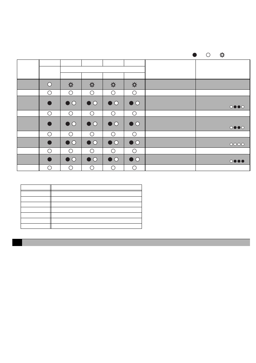
* In the case of pulse output, the LED only lights during pulse
output period.
Output
Method
Ch1
Ch2
LED5
LED4
LED3
LED2
Level
Output
: ON
: OFF
–
: ON
: OFF
–
Pulse
Output
: ON
: OFF
: ON
: OFF
* LED11 flashes each time a change in input is detected. (*1)
Input
Method
Ch1
Operation
Ch2
Operation
Ch1 Error
Ch2 Error
LED12
LED13
LED14
LED15
Level
Input
: ON
: OFF
: Error
: Normal
* LED11 flashes each time a change in input is detected. (*1)
Input
Method
Ch3
Ch4
Ch5
Ch6
LED12
LED13
LED14
LED15
Level
Input
: ON
: OFF
* LED11 flashes each time a change in input is detected. (*1)
* In the case of pulse output, the LED only lights during pulse
output period.
Output
Method
Ch3
Ch4
Ch5
Ch6
LED12
LED13
LED14
LED15
Level/
Pulse
Output
: ON
: OFF
* LED11 flashes each time a change in input is detected. (*1)
Input
Method
Ch3
Ch4
Ch5
Ch6
LED12
LED13
LED14
LED15
Level
Input
: Eroor
: Normal
14
10-2. Communication Error Status Display
If a communication error occurs, a 4-digit error code will be repeatedly displayed according to the steps shown below.
Communication error status display consists of the following 10 steps. This operation is performed repeatedly to indicate the
4-digit error code for the communication error.
Furthermore, changing SW03-8 from ON to OFF masks the "Communication Error Status Display" for 10 seconds so that
the input/output status set with SW03-6 and 7 can be displayed.
Note :On, :Off, :Flashing
The error codes that are displayed for M-NET communication errors are as shown below.
Use the following procedure to confirm operation of the system.
(1) Configure the settings of this device and the system controllers while referring to "8 Initial Setting Procedure".
(2) Perform an operation from a system controller and confirm whether a connected general-purpose device can be operated normally.
(3) In the case of using contact inputs
(a) Change the operate/stop status of the connected device and confirm whether the operation status is displayed on the system
controller.
(b) Generate an error on the connected general-purpose device and confirm whether the error is displayed on the system controller.
(4) In the case of using error interlock stop outputs
(a) Generate an error on the connected device and confirm that "Stop" is output from a contact output.
If there is a problem, check the wiring and settings.
For details on configuring settings, refer to "8 Initial Setting Procedure" and "9 Switch List".
LED11
LED12
LED13
LED14
LED15
Function
Remark
Common
Error cord display (Binary number indication)
2
3
=8
2
2
=4
2
1
=2
2
0
=1
STEP1
"Error Status Display"
Starting Point Indication
LEDs 12 to 15 flash 3 times
STEP2
Blank
Turn Off
STEP3
/
/
/
/
Error code 1000's digit
Error code 1000's digit
indication
In the case of 6,
STEP4
Blank
Turn Off
STEP5
/
/
/
/
Error code 100's digit
Error code 100's digit
indication
In the case of 6,
STEP6
Blank
Turn Off
STEP7
/
/
/
/
Error code 10's digit
Error code 10's digit indication
In the case of 0,
STEP8
Blank
Turn Off
STEP9
/
/
/
/
Error code 1's digit
Error code 1's digit indication
In the case of 7,
STEP10
Blank
Turn Off
Error Code
Description of Error
6600
Multiple address error
6601
M-NET polarity unset error
6602
Transmission processor hardware error
6603
Transmission circuit bus-busy error
6606
Communications with transmission processor error
6607
No ACK error
6608
No return of response frame
11
Test Run

WT04977X01
This product is designed and intended for use in the residential,
commercial and light-industrial environment.
This product at hand is
based on the following
EU regulations:
• Low Voltage Directive 73/23/EEC
• Electromagnetic Compatibility Directive
2004/108/EC
NOTE:
This equipment has been tested and found to comply with the limits for a Class
B digital device, pursuant to Part 15 of the FCC Rules. These limits are designed
to provide reasonable protection against harmful interference in a residential
installation. This equipment generates, uses and can radiate radio frequency
energy and, if not installed and used in accordance with the instructions, may
cause harmful interference to radio communications.
However, there is no guarantee that interference will not occur in a particular
installation.
If this equipment does cause harmful interference to radio or television
reception, which can be determined by turning the equipment off and on, the
user is encouraged to try to correct the interference by one or more of the
following measures:
- Reorient or relocate the receiving antenna.
- Increase the separation between the equipment and receiver.
- Connect the equipment into an outlet on a circuit different from that to which
the receiver is connected.
- Consult the dealer or an experienced radio/TV technician for help.
HEAD OFFICE: TOKYO BLDG., 2-7-3, MARUNOUCHI, CHIYODA-KU, TOKYO 100-8310, JAPAN
Wyszukiwarka
Podobne podstrony:
IM PAC YG63MCA WT04975X01 EN 2007
IM PAC YG60MCA WT04973X01 EN 2007
IM PAC AK30 50BC BG79U439H04 2007
IM PAC KE07DME WT05243X01 2007
IM PAC SA1ME E RG79V563H01 2007
IM PAC AH125 140 250M H WT04980X02 GB 2007
Powiedz im, Fan Fiction, Dir en Gray
IM PAC SC36NA E(WT04936X01) GB
IM PAC IF011B E IF012B E BH79D099H02 GB 09 2009
IM PAC SE51CRA WT02699X01 GB 2005
IM PAC YG81TB WT05422X02 Apr 2009
IM PAC YG83UTB WT05420X01 Apr 2009
IM PAC SE55RA E WT02925x01 pd
IM PAC AK31 51BC BG79U439K08 Sep 2010
IM PAC YT51CRA WT03594X02 GB 2005
IM PAC SA88HA E WT02522X01 pl
IM PAC IF011B E RG79D377H01 pl
IM PAC KE03DM F WT03396X01
więcej podobnych podstron