Air-Conditioners Indispensable Optional Parts
BRANCH BOX
PAC-AK51BC
PAC-AK31BC
ONLY FOR R410A OUTDOOR UNIT
ONLY FOR INDOOR USE
HFC
utilized
R410A
INSTALLATION MANUAL
For safe and correct use, please read this installation manual thoroughly before installing the air-conditioner
unit.
INSTALLATONSHANDBUCH
Zum sicheren und ordnungsgemäßen Gebrauch der Klimaanlage das Installationshandbuch gründlich
durchlesen.
MANUAL D’INSTALLATION
Veuillez lire le manual d’installation en entier avant d’installer ce climatiseur pour éviter tout accident et vous
assurer d’une utilisation correcte.
INSTALLATIEHANDLEIDING
Voor een veilig en juist gebruik moet u deze installatiehandleiding grondig doorlezen voordat u de aircondi-
tioner installeert.
MANUAL DE INSTALACIÓN
Para un uso seguro y correcto, lea detalladamente este manual de instalación antes de montar la unidad de
aire acondicionado.
MANUALE DI INSTALLAZIONE
Per un uso sicuro e corretto, leggere attentamente questo manuale di installazione prima di installare il con-
dizionatore d’aria.
MANUAL DE INSTALAÇÃO
Para segurança e utilização correctas, leia atentamente este manual de instalação antes de instalar a uni-
dade de ar condicionado.
INSTALLATIONSMANUAL
Læs venligst denne installationsmanual grundigt, før De installerer airconditionanlægget, af hensyn til sikker
og korrekt anvendelse.
INSTALLATIONSMANUAL
Läs denna installationsmanual noga för säkert och korrekt bruk innan luftkonditioneringen installeras.
MONTAJ ELKİTABI
Emniyetli ve doğru biçimde nasıl kullanılacağını öğrenmek için lütfen klima cihazını monte etmeden önce bu
elkitabını dikkatle okuyunuz.
РУКОВОДСТВО ПО УСТАНОВКЕ
Для осторожного и правильного использования прибора необходимо тщательно ознакомиться с данным руководс-
твом по установке до выполнения установки кондиционера.
ΕΓΧΕΙΡΙΔΙΟ ΟΔΗΓΙΩΝ ΕΓKATAΣTAΣHΣ
Για ασφάλεια και σωστή χρήση, παρακαλείστε διαβάσετε προσεχτικά αυτό το εγχειρίδιο εγκατάστασης πριν
αρχίσετε τηv εγκατάσταση της μονάδας κλιματισμού.
Deutsch
Français
English
VOOR DE INSTALLATEUR
Nederlands
PARA EL INSTALADOR
Español
PER L’INSTALLATORE
Italiano
PARA O INSTALADOR
Português
TIL INSTALLATØREN
Dansk
FÖR INSTALLATÖREN
Svenska
MONTÖR İÇİN
Türkçe
ДЛЯ УСТАНОВИТЕЛЯ
Русский
FÜR INSTALLATEURE
POUR L’INSTALLATEUR
FOR INSTALLER
Ελληνικά
ΓΙA AYΤΟΝ ΠΟΥ ΚΑΝΕΙ ΤΗΝ ΕΓΚΑTAΣΤAΣΗ

2
Contents
1. Safety precautions .............................................................................................2
2. Selecting a location for installation ....................................................................2
3. Confirming supplied accessories .......................................................................3
4. Dimensions and required servicing space of Branch Box .................................3
5. Refrigerant piping ..............................................................................................4
6. Mounting the branch box ...................................................................................5
7. Installing refrigerant piping.................................................................................5
8. Installing drain piping .........................................................................................6
9. Electrical work....................................................................................................7
10. Test run..............................................................................................................9
1. Safety precautions
► Before installing the unit, make sure you read all the “Safety precau-
tions”.
► Please report to your supply authority or obtain their consent before
connecting this equipment to the power supply system.
After installation work has been completed, explain the “Safety Precautions,” use,
and maintenance of the unit to the customer according to the information in the
Operation Manual and perform the test run to ensure normal operation. Both the
Installation Manual and Operation Manual must be given to the user for keeping.
These manuals must be passed on to subsequent users.
: Indicates a part which must be grounded.
Warning:
Carefully read the labels affixed to the main unit.
Warning:
Describes precautions that must be observed to prevent danger of injury or
death to the user.
Caution:
Describes precautions that must be observed to prevent damage to the unit.
This installation manual is only for the branch box installation. In installing the indoor units and outdoor units, refer to the installation manual attached to
each unit.
Warning:
• Ask a dealer or an authorized technician to install the unit.
• For installation work, follow the instructions in the Installation Manual and
use tools and pipe components specifically made for use with refrigerant
specified in the outdoor unit installation manual.
• The unit must be installed according to the instructions in order to minimize
the risk of damage from earthquakes, typhoons, or strong winds. An incor-
rectly installed unit may fall down and cause damage or injuries.
• The unit must be securely installed on a structure that can sustain its
weight.
• If the air conditioner is installed in a small room, measures must be taken
to prevent the refrigerant concentration in the room from exceeding the
safety limit in the event of refrigerant leakage. Should the refrigerant leak
and cause the concentration limit to be exceeded, hazards due to lack of
oxygen in the room may result.
• Ventilate the room if refrigerant leaks during operation. If refrigerant comes
into contact with a flame, poisonous gases will be released.
• All electric work must be performed by a qualified technician according to
local regulations and the instructions given in this manual.
• Use only specified cables for wiring.
• The terminal block cover panel of the unit must be firmly attached.
• Use only accessories authorized by Mitsubishi Electric and ask a dealer or
an authorized technician to install them.
• The user should never attempt to repair the unit or transfer it to another lo-
cation.
• After installation has been completed, check for refrigerant leaks. If refriger-
ant leaks into the room and comes into contact with the flame of a heater or
portable cooking range, poisonous gases will be released.
• Be sure to connect the power supply cords and the connecting wires for the
indoor units, outdoor units, and branch boxes directly to the units (no inter-
mediate connections). Intermediate connections can lead to communication
errors if water enters the cords or wires and causes insufficient insulation
to ground or a poor electrical contact at the intermediate connection point.
(If an intermediate connection is necessary, be sure to take measures to
prevent water from entering the cords and wires.)
Caution:
• Make sure that the refrigerant pipes are well insulated to prevent conden-
sation. Incomplete insulation may cause condensation on the surface of
pipes, wetting of the ceiling, floor and other important properties.
• Make sure that the drainage pipe is carried out correctly following this man-
ual and that it is insulated in order to prevent condensation. Any deficiency
caused by piping may result in water leakage, wetting of the
ceiling, floor and other personal properties.
2. Selecting a location for installation
* The branch box is only for indoor use.
Please attach the special optional cover (PAC-AK350CVR-E) to install the
branch box in the outdoors.
• Ensure that the branch box is installed in a location which facilitates servicing
and maintenance. (ensure that the required maintenance hole or service space
is available).
• Do not install near bedrooms. The sound of refrigerant flowing through
the piping may sometimes be audible.
• Ensure that it is located where noise in operation will not be a problem.
After power is supplied or after an operation stop for a while, a small
clicking noise may be heard from the inside of the branch box. The elec-
tronic expansion valve is opening and closing. The unit is not faulty.
• Determine the route of refrigerant piping, drain piping, and electrical wiring be-
forehand.
• Ensure that the location of the installation is such that the length of refrigerant
piping is within the specified limits.
• Ensure that the unit is out of reach of children at least 1.8 m above the floor.
• Ensure that the branch box is installed above the ceiling of corridor, bath room,
etc., where persons are not regularly there (Avoid installing at around center of
the room.) for maintenance.
• Ensure that the location of the installation is such that the down-gradient of the
drain piping is greater than 1/100.
• Do not install in location that is hot or humid for long periods of time.
* Ensure that the unit is installed in a location able to support its weight.
Warning:
Ensure that the unit is installed firmly in a location able to support its weight.
If the installation is of insufficient strength the unit may fall, resulting in injury.
: Type A
: Type B
S1
S2
S3
S1
S2
S3
S1
S2
S3
S1
S2
S3
S1
S2
S3
S1
S3
S2
TB3B
TB3
C
TB3A
TB3D
TB3E
TB2B
320
402
24
12
198
450
91
55
73
25
75
75
75
75
200
23
39
65
95
61
280
39
70
35
68
79
25
25
25
25
21
E
D
C
B
E
D
C
B
A
A
ø20
50 34
(mm)
200
Type A
ø
2
0
Type B
B
A
3
3. Confirming supplied accessories
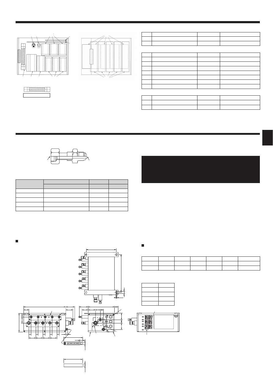
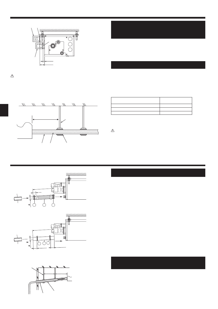
4. Dimensions and required servicing space of Branch Box
PAC-AK51BC (5-branches type)
3.1. Check the Branch Box accessories and parts
Accessory name
Q’ty
Washer (with insulation)
4
Washer
4
For refrigerant piping joint
Accessory name
Q’ty
Pipe cover (Liquid)
1
TO OUTDOOR UNIT
Pipe cover (Gas)
1
TO OUTDOOR UNIT
Pipe cover (Liquid)
5
TO INDOOR UNITS
Pipe cover (Gas)
5
TO INDOOR UNITS
Joint cover (Liquid)
3
Joint cover (Gas)
3
Band
24
For drain pipe
Accessory name
Q’ty
Drain hose
1
Type A or Type B
Band
2
Fig. 3-1
Optional different (deformed) joints
Fig. 4-1
* Please connect 2 indoor units or more with one system.
* 1-2 branch boxes may be connected to one outdoor unit.
* Suspension bolt : W3/8 (M10)
* Refrigerant pipe flared connection
* The piping connection size differs according to the type and capacity of
indoor units. Match the piping connection size for indoor unit and branch
box. If the piping connection size of branch box does not match the pip-
ing connection size of indoor unit, use optional different-diameter (de-
formed) joints to the branch box side. (Connect deformed joint directly to
the branch box side.)
Suspension bolt pitch
To indoor unit
Flexible drain hose (Accessory)
Drain pipe connection (VP-16)
To outdoor unit
Service panel (for LEV, THERMISTOR)
3-WIRE BAND
Electric cover
3-electric wire inlet
Terminal block (to indoor unit)
Terminal block (to outdoor unit)
* Ensure that the branch box is installed as shown on the below drawing. Leg must
be located on top. Otherwise drainage will not be properly performed.
PAC-AK51BC (Fig. 4-2)
Suspension bolt: W3/8 (M10)
Refrigerant pipe flared connection
A
B
C
D
E
To outdoor unit
Liquid pipe
ø6.35
ø6.35
ø6.35
ø6.35
ø6.35
ø9.52
Gas pipe
ø9.52
ø9.52
ø9.52
ø9.52
ø12.7
ø15.88
Drain hose size : O.D. 20 (VP16)
Model name
Connected pipes diameter
Diameter A
Diameter B
mm
mm
mm
MAC-A454JP
ø9.52 → ø12.7
ø9.52
ø12.7
MAC-A455JP
ø12.7 → ø9.52
ø12.7
ø9.52
MAC-A456JP
ø12.7 → ø15.88
ø12.7
ø15.88
PAC-493PI
ø6.35 → ø9.52
ø6.35
ø9.52
PAC-SG76RJ-E
ø9.52 → ø15.88
ø9.52
ø15.88
Fig. 4-2
Conversion formula
1/4 F
ø6.35
3/8 F
ø9.52
1/2 F
ø12.7
5/8 F
ø15.88
3/4 F
ø19.05
S1
S2
S3
S1
S2
S3
S1
S2
S3
S1
S2
S3
TB3B
TB3
C
TB3A
TB2B
320
402
24
12
198
450
91
205
73
75
75
200
23
39
65
95
61
280
39
70
35
68
79
25
25
25
21
C
B
A
C
B
A
ø
20
50 34
(mm)
200
Type A
ø
2
0
Type B
(3)
Min.250
(1)
(2)
450
280
198
180-200
*3
*2
B
A
Min. 50
Min. 250
*1
Min.
250
Min.30
Min.
250
450
4
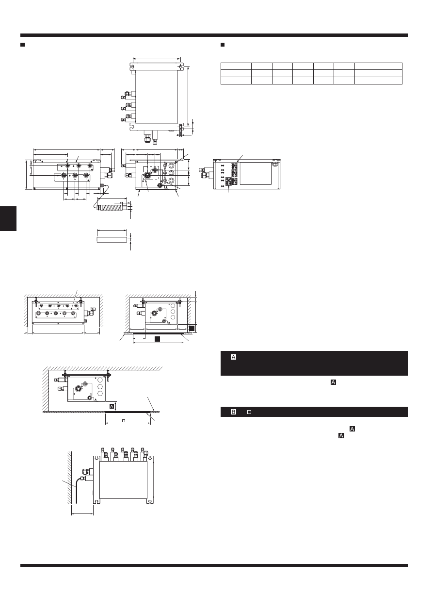
4. Dimensions and required servicing space of Branch Box
PAC-AK31BC (3-branches type)
PAC-AK31BC (Fig. 4-3)
Suspension bolt: W3/8 (M10)
Refrigerant pipe flared connection
A
B
C
To outdoor unit
Liquid pipe
ø6.35
ø6.35
ø6.35
ø9.52
Gas pipe
ø9.52
ø9.52
ø9.52
ø15.88
Drain hose size: O.D.20 (VP16)
4.1. Space required for installation and servicing
(1) Front View (Fig. 4-4)
Branch box
On the side of piping
(2) Side View (Fig. 4-5, Fig. 4-6)
For indoor installations
Ceiling board
Maintenance hole
PCB side
*1: A minimum 350 mm is required for 90° bends in refrigerant piping.
*2: is “ Min. 200 mm ” <recommendation>.
(Premise: The slope of drain piping is securable 1/100 or more. Required
200 mm or more, when not securable.)
In the case of less than 200 mm (for example
is 100 mm), the exchange work
of Branch box from a maintenance hole becomes difficult (Only exchange work
of a PCB, linear expansion valve coils, sensors and drain pan is possible).
In the case of “ 450”, prepare a maintenance hole at a PCB side (as it is shown
in Fig. 4-6), and “Min. 300 mm” is needed as distance
.
In the case of less than 300 mm (for example
is 100 mm), the exchange
work of Branch box, linear expansion valve coils, sensors, and drain pan from a
maintenance hole becomes difficult (Only exchange work of a PCB is possible).
(3) Top View (Fig. 4-7)
Refrigerant piping
When facing in the opposite direction to the refrigerant piping.
*3: is “ 600 mm ” <recommendation>.
5. Refrigerant piping
* Always follow the specifications written in the installation manual of the outdoor unit. Exceeding these requirements may cause reduced performance of the
equipment, and malfunctions.
Fig. 4-7
Fig. 4-3
Fig. 4-4
Fig. 4-6
Fig. 4-5
(mm)
()
A
*
50
.
ni
M
50
.
ni
M
D
Min.30
ll
a
W
Wall mount
5
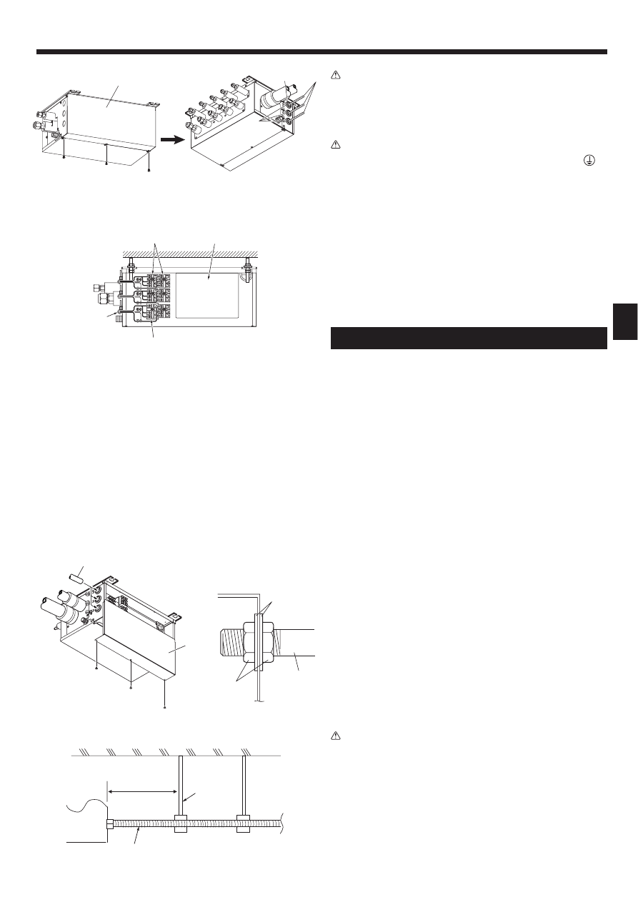
6. Mounting the Branch Box
(1) Install the suspension bolts (procure locally) at the specified pitch (Fig. 4-2, 4-3).
(2) Fit the washers and nuts ( , , procure locally) to the suspension bolts.
(Fig. 6-1)
(3) Hang the unit on the suspension bolts.
(4) Fully tighten the nuts (check ceiling height).
(5) Use a level to adjust the branch box to the horizontal.
When unit is hung and nuts tightened
Suspension bolt
Nuts
Washer (with cushion)
Ensure that cushion faces downwards
Washer (without cushion)
Nut (procure locally)
Suspension bolt
Ensure that this face is always installed upwards.
Ceiling board.
Note:
* Refer to “4-1”.
Caution:
• Always install the unit horizontally.
• This unit may be installed suspended from the ceiling.
•
This unit may only be installed vertically, as shown in the diagram below.
(Side is facing up.)
• Incorrect installation may result in the drain overflowing.
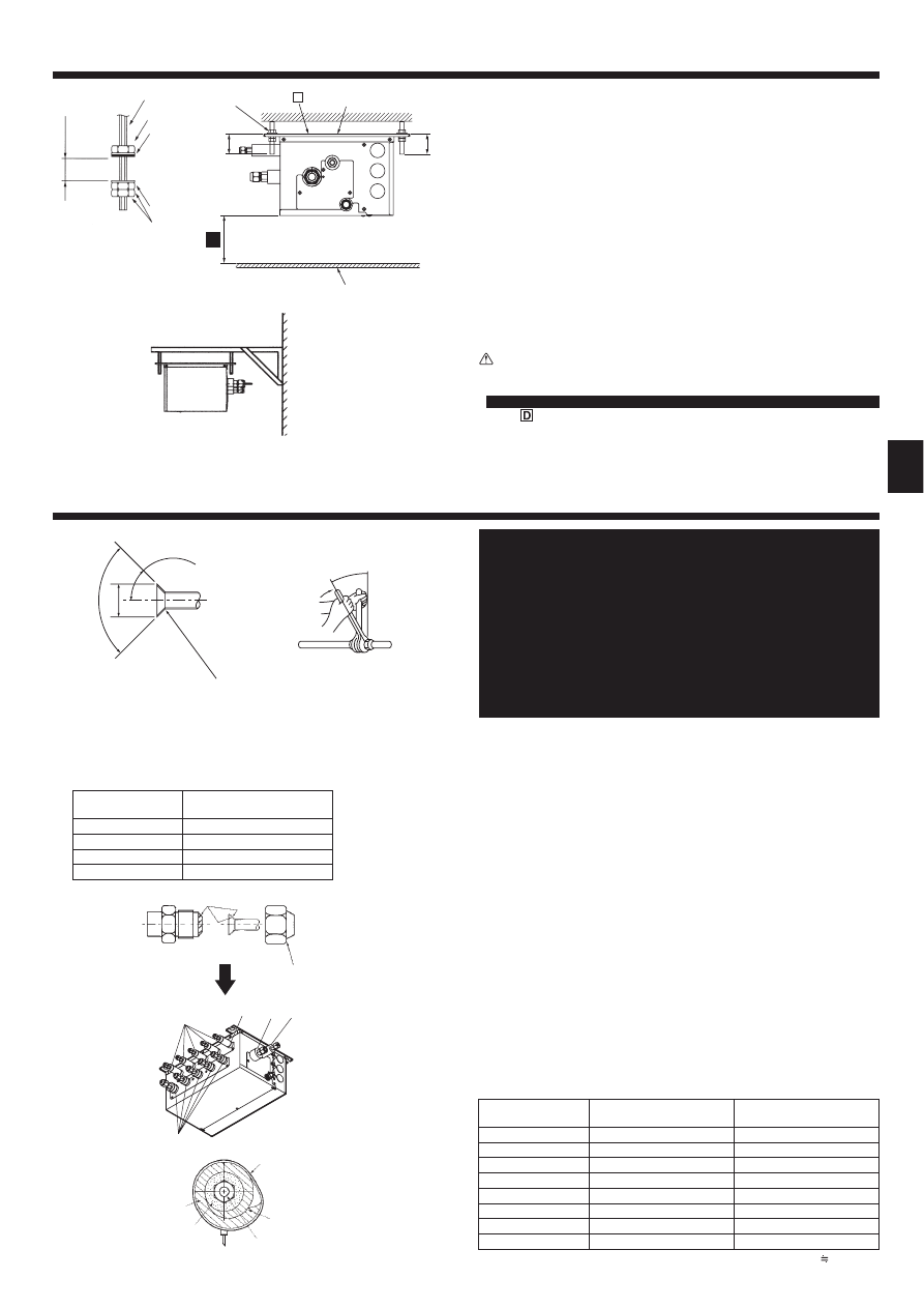
7. Installing refrigerant piping
Flare cutting dimensions
Flare nut tightening torque
90
°
±
0.5°
øA
R0.4~R0.8
45°± 2°
Flare cutting dimensions
Table 1
Copper pipe O.D.
(mm)
Flare dimensions
øA dimensions (mm)
ø6.35
8.7 - 9.1
ø9.52
12.8 - 13.2
ø12.7
16.2 - 16.6
ø15.88
19.3 - 19.7
► Connect the liquid and gas pipes of each indoor unit to the same end
connection numbers as indicated on the indoor unit flare connection
section of each Branch Box. If connected to wrong end connection
numbers, it doesn’t work normally. (Fig. 7-1)
► When connecting indoor units, make sure to connect refrigerant pipes
and connection wires to the appropriate connection ports marked with
matching alphabets. (Ex. A, B, C, D, E)
Note:
Be sure to mark all the local refrigerant piping (liquid pipes, gas pipes, etc.)
for each indoor unit designating clearly which room it belongs in. (Ex. A, B,
C, D, E)
► List indoor unit model names in the name plate on the control box of
Branch Box (for identification purposes).
► To prevent water dripping from the refrigerant piping, install sufficient
thermal insulation.
► When using commercially available refrigerant piping, ensure that both
liquid and gas piping are wrapped with commercially available thermal
insulation materials (insulation materials at least 12 mm thick and able
to withstand temperatures in excess of 100 °C).
► Refer to the installation manual of the outdoor unit when creating a
vacuum and opening or closing valves.
(1) Remove the flared nuts and caps from the branch box.
(2) Flare the ends of the liquid and gas piping, and apply refrigeration oil (procure
locally) to the flared seat.
(3) Connect the refrigerant piping immediately. Always tighten the flared nuts
to the torque specified in the table below using a torque wrench and double
spanner.
(4) Press the pipe covers and on the liquid piping against the unit and wrap
to hold in place.
(5) Press the pipe covers and on the gas piping against the unit and wrap to
hold in place.
(6) Apply the supplied bands
at a position 10 - 20 mm from each end of the
pipe covers (
).
(7) If the indoor unit is not connected, fit the supplied pipe covers (with caps,
and ) to the branch box refrigerant piping connections to prevent condensa-
tion dripping from the pipes.
(8) Clamp the pipe covers (
) in place with the supplied bands .
Flare nut tightening torque
Table 2
Copper pipe O.D.
(mm)
Flare nut O.D.
(mm)
Tightening torque
(N·m)*
ø6.35
17
14 - 18
ø6.35
22
34 - 42
ø9.52
22
34 - 42
ø9.52
26
49 - 61
ø12.7
26
49 - 61
ø12.7
29
68 - 82
ø15.88
29
68 - 82
ø15.88
36
100 - 120
* 1N·m
10 kgf·cm
Fig. 6-1
Fig. 6-2
* Purchase an appropriate
bracket locally if the unit
is to be mounted on a
wall.
Fig. 7-1
Fig. 7-2
Fig. 7-3
1.5 to 2 m
25 cm
200
23
20
11
11
10
10
200
11
11
10 to 20
10 to 20
20
6
7. Installing refrigerant piping
8. Installing drain piping
10~20
30~50
(mm)
Caution:
Tighten the flare nut with a torque wrench in the specified method.
Overtightening will cause the flare nut to crack and it will cause refrigerant
leakage over a period of time.
Apply refrigeration oil to the entire (Fig. 7-2) surface of the flared seat.
Basically use flared nuts fitted to the body (commercially available flared nuts
may crack).
Note:
A special flare nut (optional or attached to the indoor unit) is needed to
some indoor units.
Please refer to the installation manual of outdoor unit and indoor unit for
details.
Band
Pipe covers
Tighten
Refrigerant piping
Thermal insulation for refrigerant piping
► Use the following procedures for indoor connection part which indoor
unit is not connected. (Fig. 7-4)
(1) In order to prevent refrigerant leaks, make sure that the flare nuts are tightened
according to the specified torques* in Table 3.
* Refrigerant may also leak if the flare nuts are tightened more than the speci-
fied torques.
(2) In order to prevent condensation, install the pipe covers
and fasten them
with the supplied bands
.
Table 3
Diameters of branch box openings for
connecting indoor units (mm)
Tightening torque
(N·m)
ø6.35
13 ± 2
ø9.52
30 ± 2
ø12.7
50 ± 2
► Refrigerant charge:
Refer to the installation manual of the outdoor unit.
Use only R410A refrigerant (use of other refrigerants may cause troubles).
• To ensure that the drain piping has a down-gradient (greater than 1/100),
do not make traps or humps in piping.
• Install thermal insulation to prevent condensation dripping.
• Ensure that the horizontal length (not diagonal length) of drain piping does not
exceed 20 m. If the drain piping extends over a significant distance, install sup-
ports to ensure that the piping does not sag. Do not fit air bleed pipes under
any circumstances (water may exit from air bleed pipes).
• Do not fit odor traps at drain piping outlets.
• Install drain outlets in locations where odors will not present problems.
• Do not place drain piping directly in drains which may contain sulfurous gases.
• Drain piping may be installed in any direction provided the above requirements
are followed.
• Keep bends of attached drain hose to a maximum of 45°.
(1) Apply PVC adhesive (procure locally) to the drain connection on the branch
box and push the attached drain hose
onto the connection as far as it will
go. (Fig. 8-1)
(2) Insert a hard PVC pipe (VP-16, procure locally) into the attached drain hose
and glue it together and fix it. (Fig. 8-1)
VP-16 procured locally
Thermal insulation
(3) Fit a band
to the attached drain hose
(Fig.8-1)
(4) Ensure that the drain piping down-gradient is greater than 1/100. (Fig. 8-2)
Supports
Down-gradient greater than 1/100.
Thermal insulation
Type A
Type B
(mm)
Note:
The drain hose is available in either Type A or Type B.
The installation methods are different between Type A and Type B.
Fig. 7-5
Caution:
To avoid excessive strain on the branch box, support piping with one or more
support(s) 1.5 m or less from the branch box.
Refer to Fig. 7-5 as an example.
Refrigerant piping
Thermal insulation for refrigerant piping
Fig. 7-4
Fig. 8-1
Fig. 8-2
1.5 m or less
Support
Pipe cover
7
9. Electrical work
S1
S2
S3
S1
S2
S3
S1
S2
S3
S1
S2
S3
S1
S2
S3
S1
S3
S2
TB3C
TB3
E
TB3A
TB3B
TB3D
TB2B
► Cautions for electrical work
Warning:
• Always use dedicated circuits with breakers, and at the rated voltage.
Power supply circuits with insufficient capacity, and bad workmanship dur-
ing installation, may result in electric shock or fire.
• Always ensure that electrical wiring inlets are sealed when the branch box
is installed outdoors.
Rainwater on the terminal blocks may result in fire or malfunction.
Caution:
• Be sure to establish an earth. Do not earth the unit to a utility pipe,
arrester, or telephone earth.
Incomplete earth may cause electrical shock. A high surge current from
lightning or other sources may cause damage to the air conditioner.
• Use the specified electrical wiring and ensure that it is connected properly,
and that it is not under tension.
Failure to follow these requirements may result in broken wiring, heating,
or fire.
► Wiring connecting branch box and outdoor unit, and branch box and in-
door units, functions as both power supply and signal cable. Connect this
wiring in accordance with the terminal block numbers to ensure correct
polarity.
► Ensure that the appropriate refrigerant piping and electrical wiring are
connected to each indoor unit. Incorrect wiring will interfere with the cor-
rect operation of the unit.
• Support the wiring coming from the branch box to avoid excessive strain
on the branch box.
(Fit the support 1.5 m or less along the cable from the branch box.)
► Connect refrigerant pipes and connection wires to the appropriate ports
marked with matching alphabets (Ex. A, B, C, D, E) on this unit.
► Always fix each ground wire separately with a ground screw.
► To prevent that wiring installed in the ceiling is chewed by rats etc., it
should be installed in wiring conduit.
1. Remove the screws in the cover. (Fig. 9-1)
2. Remove the cover.
3. Pass the wiring into the branch box. (Fig. 9-2)
4. Fix each wire in place with a wiring clamp. (Fig. 9-3)
5. Firmly connect each wire to the appropriate terminal block. (Fig. 9-3)
6. Replace the cover.
7. When the branch box is installed outdoors, ensure that the wiring inlets are
sealed with putty to prevent entry of rainwater. (Fig. 9-2)
Electric cover
3-Bush
Seal
Wiring
BC controller
Band
Terminal block: TB2B <To outdoor unit> ø1.6 - ø2.0
Terminal block: TB3A-TB3E <To indoor unit> ø1.6
9.1. When using wiring conduit (Fig. 9-4)
Replace the horizontal cover when the wiring conduit has been fixed in place.
Cover
Wiring conduit
Washer
Nut
Wiring conduit
Wiring conduit of up to 1" OD may be used.
(1) When using 1" OD wiring conduit, remove the bush and fix to the branch box.
Remove the horizontal cover while fixing to the branch box.
(2) When using wiring conduit of 3/4" OD or smaller, notch the bush and insert the
wiring conduit approximately 100 mm into the branch box.
* Replace the horizontal cover when the wiring conduit has been fixed in place.
Caution:
To avoid excessive strain on the branch box, support a conduit pipe with
one or more support(s) 1.5 m or less from the branch box.
Refer to Fig. 9-5 as an example.
*
Fig. 9-3
Fig. 9-1
Fig. 9-2
Fig. 9-4
Fig. 9-5
1.5 m or less
Support
8
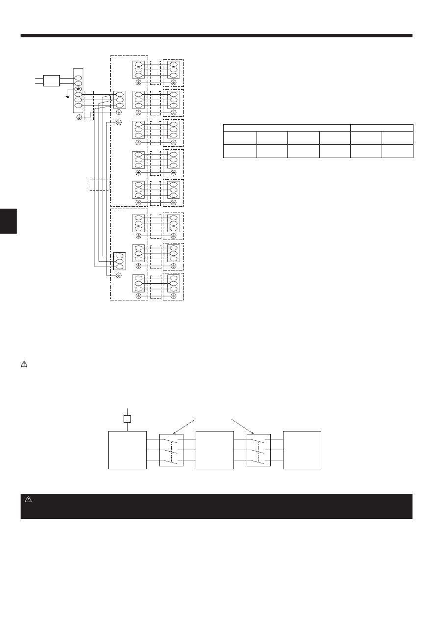
9. Electrical work
Branch box
#
2
(3-branch type)
<example>
(in case of 2-branch boxes)
L
N
S1
S2
S3
S1
S2
S3
S1
S2
S3
S1
S2
S3
TB3A
S1
S2
S3
S1
S2
S3
TB3B
TB2B
S1
S2
S3
S1
S2
S3
TB3C
S1
S2
S3
S1
S2
S3
TB3D
S1
S2
S3
S1
S2
S3
TB3E
(A)
(A)
(B)
S1
S2
S3
S1
S2
S3
TB3A
S1
S2
S3
S1
S2
S3
S1
S2
S3
TB3B
S1
S2
S3
S1
S2
S3
TB3C
(D)
(D)
(D)
(D)
(D)
(D)
(D)
(D)
(C)
A ROOM
Branch box
#
1
(5-branch type)
Outdoor unit
Indoor unit
Circuit
breaker
E ROOM
B ROOM
C ROOM
D ROOM
F ROOM
G ROOM
H ROOM
Indoor unit
TB2B
(C)
S1
S2
S3
S1
S2
S3
S1
S2
S3
S1
S2
S3
Power supply
Outdoor unit
Isolator (Switch)
3 poles isolator (Switch)
“A-control”
Indoor unit
Branch
box
Warning:
In case of A-control wiring, there is high voltage potential on the S3 terminal caused by electrical circuit design that has no electrical insulation between power
line and communication signal line. Therefore, please turn off the main power supply when servicing. And do not touch the S1, S2, S3 terminals when the power
is energized. If isolator should be used between outdoor unit and branch box/indoor unit and branch box, please use 3-poles type.
Caution:
After using the isolator, be sure to turn off and on the main power supply to reset the system. Otherwise, the outdoor unit may not be able to detect the
branch box(es) or indoor units.
9.2. External wiring procedure (Fig. 9-6)
Power supply: Single phase 220/230/240 V, 50 Hz 220 V, 60 Hz
Note:
Power supply input: Outdoor unit only. Connect the lines (C), (D) in accor-
dance with the terminal block names to ensure correct polarity.
As for lines (C), S1 and S2 are for connecting the power source.
And S2 and S3 are for signals. S2 is a common cable for the power source
and signal.
Wire diameter
Breaker
(A) Main
power line
(B) Earth
line
(C) Signal line/
Earth line
(D) Signal line/
Earth line
Interrupting
current
Performance
characteristic
6.0 mm²
6.0 mm²
1.5 mm² *2/
Min. 1.5 mm²
1.5 mm²/
Min. 1.5 mm²
*1
*1
When using twisted wire for the wiring, the use of round terminal is required.
*1 Refer to the installation manual of the outdoor unit.
*2 Max 45 m (“Outdoor unit - Branch box #1” plus “Branch box #1 - Branch box
#2”). If 2.5 mm² used, Max 55 m.
Notes: 1. Wiring size must comply with the applicable local and national
code.
2. Power supply cords and Indoor unit/Branch box/Outdoor unit con-
necting cords shall not be lighter than polychloroprene sheathed
flexible cord. (Design 60245 IEC 57)
3. Install an earth line longer than power cables.
Fig. 9-6
S1
S2
S3
(3C Flat cable
s 2)
9
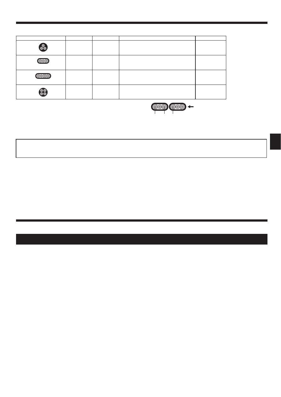
9. Electrical work
WIRING SPECIFICATIONS
(OUTDOOR-BRANCH BOX CONNECTING CABLE)
Cross section of cable
Wire size (mm²) Number of wires
Polarity
L (m)*6
Round
2.5
3
Clockwise : S1-S2-S3
* Pay attention to stripe of yellow and green
(50)
*2
Flat
2.5
3
Not applicable
(Because center wire has no cover finish)
Not applicable
*5
Flat
1.5
4
From left to right : S1-Open-S2-S3
(45)
*3
Round
2.5
4
Clockwise : S1-S2-S3-Open
*Connect S1 and S3 to the opposite angle
(55)
*4
10. Test run
• Refer to the “Test run” section of the installation manual of the indoor units and outdoor unit.
• When installation of the indoor unit, branch box, and outdoor unit is complete, begin test run to check for water leaks in the branch box.
• After power is supplied or after an operation stop for a while, a small clicking noise may be heard from the inside of the branch box. The electronic expan-
sion valve is opening and closing. The unit is not faulty.
• Be sure to perform the test run for each indoor unit. Make sure each indoor unit operates properly following the installation manual attached to the unit.
• If you perform the test run for all indoor units at once, you cannot detect any erroneous connection, if any, of the refrigerant pipes and the indoor/outdoor unit connecting
wires.
*1 :Power supply cords of appliances shall not be lighter than design 60245 IEC or
60227 IEC.
*2 : In case that cable with stripe of yellow and green is available.
*3 : In case of regular polarity connection (S1-S2-S3), wire size is 1.5 mm².
*4 : In case of regular polarity connection (S1-S2-S3).
*5 : In the flat cables are connected as this picture, they can be used up to 55 m.
*6 : Mentioned cable length is just a reference value.
It may be different depending on the condition of installation, Humidity or
materials, etc.
Be sure to connect the outdoor-branch box/indoor-branch box connecting cables directly to the units (no intermediate connections).
Intermediate connections can lead to communication errors if water enters the cables and causes insufficient insulation to ground or a poor electrical contact at the in-
termediate connection point.
Wyszukiwarka
Podobne podstrony:
IM PAC AK30 50BC BG79U439H04 2007
IM PAC SH83 84 85 86DM E RG79V973H02 Nov 2010
IM PAC KE07DME WT05243X01 2007
IM PAC SC36NA E(WT04936X01) GB
IM PAC IF011B E IF012B E BH79D099H02 GB 09 2009
IM PAC SE51CRA WT02699X01 GB 2005
IM PAC SA1ME E RG79V563H01 2007
IM PCA RP50 140KAQ RG79D720H01 Nov 2010
IM PAC YG66DCA WT04977X01 EN 2007
IM PAC YG81TB WT05422X02 Apr 2009
IM PAC YG63MCA WT04975X01 EN 2007
IM PAC YG83UTB WT05420X01 Apr 2009
IM PAC SE55RA E WT02925x01 pd
IM PAC YG60MCA WT04973X01 EN 2007
IM PAC AH125 140 250M H WT04980X02 GB 2007
IM PAC YT51CRA WT03594X02 GB 2005
IM PAC SA88HA E WT02522X01 pl
IM PAC IF011B E RG79D377H01 pl
IM PAC KE03DM F WT03396X01
więcej podobnych podstron