- 1 -
• Before installing the Electric Box, please read the following safety precautions carefully to ensure proper installation.
• Observe the following precautions to ensure safety.
• The following symbols are used in this manual to indicate the type and severity of potential consequences that may result when
given instructions are not followed exactly as stated.
• After the completion of installation, perform a test run to confirm proper operation.
• Retain this manual for future reference. When the unit is reinstalled or repaired, make this manual available to those who provide
these services. Make sure that the manual is passed on to any future air condition system users.
1 Safety Precautions
WARNING
Indicates a risk of death or serious injury.
CAUTION
Indicates a risk of injury or damage to the product.
WARNING
CAUTION
Air-conditioner Network System Optional Parts
Electric Box for AG-150A
PAC-YG83UTB
Installation Manual
Applicable
Model
Centralized Controller
AG-150A
Only a dealer or qualified technician should replace
the unit.
Improper replacement by an unqualified person may result
in electric shock or fire.
The Electric Box should be installed on a surface that
is strong enough to support the weight of the unit.
If the Electric Box is installed on a surface that lacks the
strength to support it, it may fall and cause injury.
Do not attempt to modify or repair the Electric Box.
Modification or improper repair may result in electric shock
or fire. Consult your dealer when repairs are necessary.
Install the Electric Box properly according to the
instructions detailed in this Installation Manual.
Improper installation by an unqualified person may result in
electric shock or fire.
Electric work must be performed by authorized
personnel according to the local regulations and the
instructions detailed in the Installation Manual.
Inadequate circuit capacity or improper installation may
result in electric shock or fire.
Ask your dealer or an authorized technician to move
the Electric Box.
Improper installation by an unqualified person may result in
electric shock or fire. Consult your dealer or a qualified
technician.
Do not install the Electric Box where there is a risk of
leaking flammable gas.
If the leaked gas accumulates around the Electric Box, it
may ignite and cause an explosion.
Do not use the Electric Box in an environment that has
high concentrations of oil, steam, or sulfuric gas.
These substances may have adverse effects on the
performance of the Electric Box or damage its parts.
Seal the wire access holes with putty to prevent dew,
water, and insects from entering to avoid electric
shock.
Do not install this Electric Box in a place that has the
potential for steam, such as a bathroom or kitchen.
Steam may cause an electric shock or a unit malfunction.
Do not install this Electric Box where an acid, alkaline
solution, or special chemical spray is used frequently
to avoid electric shock or malfunction.
Keep the cables from coming in direct contact with the
edges of the wire access holes.
If the cables are damaged, they may cause electric shock
or fire.
This Electric Box is for exclusive use with the AG-150A
and cannot be used with other devices.
- 2 -
The Installation Manual and the parts listed below are included with the package.
* Leave the Electric Box in the package until ready to install to protect it from damage.
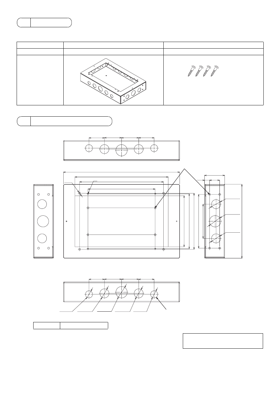
2 Parts List
Name
1
Electric Box (PAC-YG83UTB)
2
Mounting screws
Quantity
1
4
Shape
3 External Dimensions
NOTE
There is no top or bottom orientation.
Wood screws M4×20
* If the Electric Box is installed on a non-wood surface,
select an appropriate type of screws (4 pcs.) to suit
the structure type.
Check that the wall is strong enough to support the
weight of the Electric Box (PAC-YG83UTB:2.0 kg).
ø21.5
(
7
/
8
)
ø27.1
(1-
1
/
8
)
ø27.1
(1-
1
/
8
)
ø27.1
(1-
1
/
8
)
ø34
(1-
6
/
17
)
ø27.1
(1-
1
/
8
)
ø21.5
(
7
/
8
)
ø34
(1-
6
/
17
)
346 (13-
5
/
8
)
278 (11)
250 (9-
7
/
8
)
200 (7-
7
/
8
)
M4
ø6 (
2
/
9
)
163 (6-
7
/
16
)
167 (6-
5
/
8
)
102 (4-
1
/
16
)
15
(
5
/
8
)
60
(2-
3
/
8
)
30
(1-
3
/
16
)
51 (2-
1
/
16
)
51 (2-
1
/
16
)
46 (1-
13
/
16
)
46 (1-
13
/
16
)
51 (2-
1
/
16
)
51 (2-
1
/
16
)
46 (1-
13
/
16
)
46 (1-
13
/
16
)
152 (6)
160 (6-
5
/
16
)
220
(8-
11
/
18
)
Unit: mm (in)
Knockout hole
Mounting holes
Weight
2.0 kg (4-
7
/
16
lb)
- 3 -
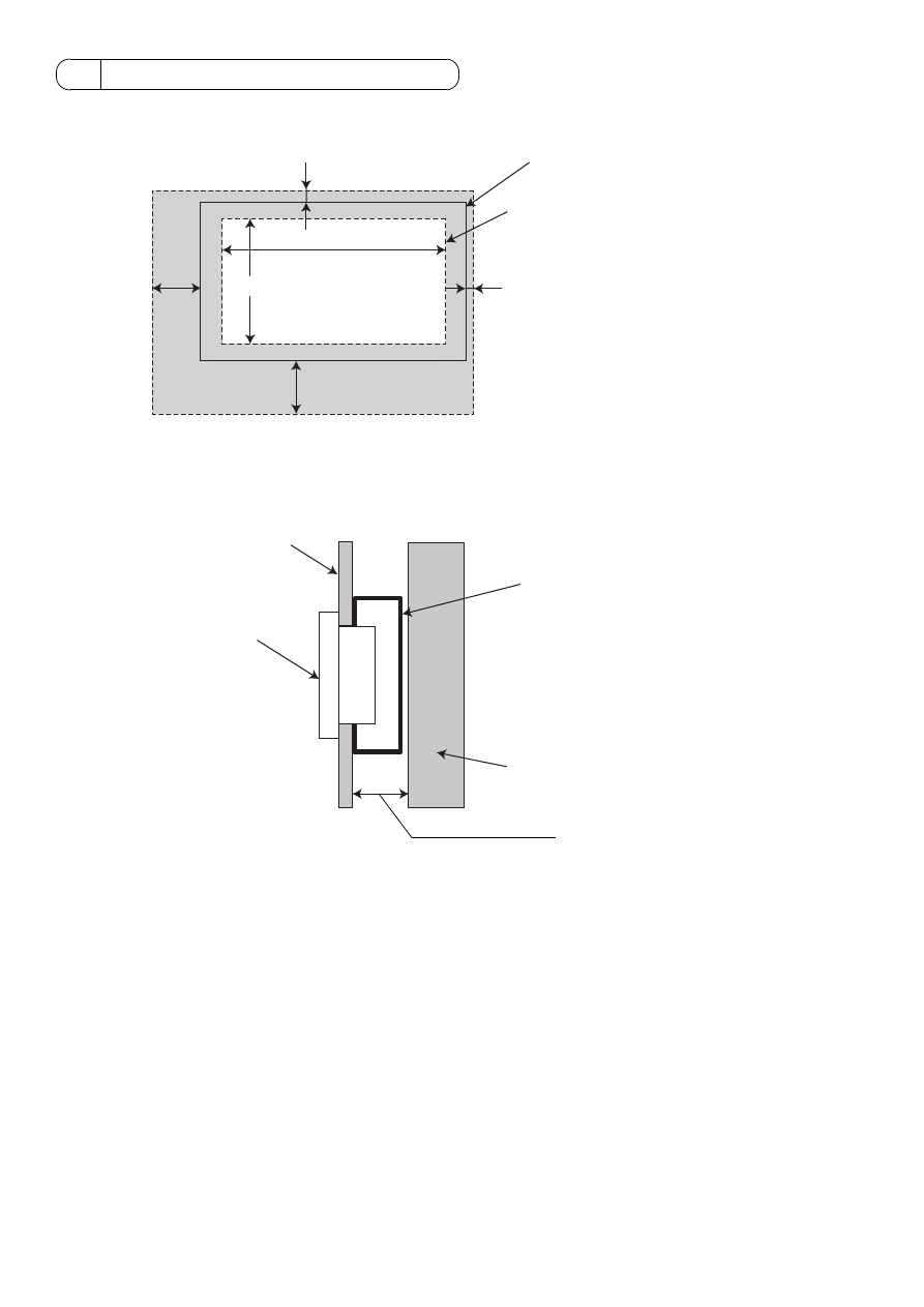
1. Required installation space
Install the electric box so that there is enough wall space around the Centralized controller AG-150A as shown below.
2. Required space behind the wall
A minimum space of 60 mm (2-
3
/
8
in) is required behind the wall.
4 Selecting an Installation Site
185(7-
5
/
16
)
300(11-
13
/
16
)
127(5)
102.5(4-
1
/
16
)
7(
5
/
16
)
17.5(
3
/
4
)
Electric Box size (PAC-YG83UTB)
Centralized controller (AG-150A) size
Unit: mm (in)
Inside wall
Electric Box (PAC-YG83UTB)
60 mm (2-
3
/
8
in) minimum
Building structure (posts, etc.)
Centralized
controller (AG-150A)
- 4 -
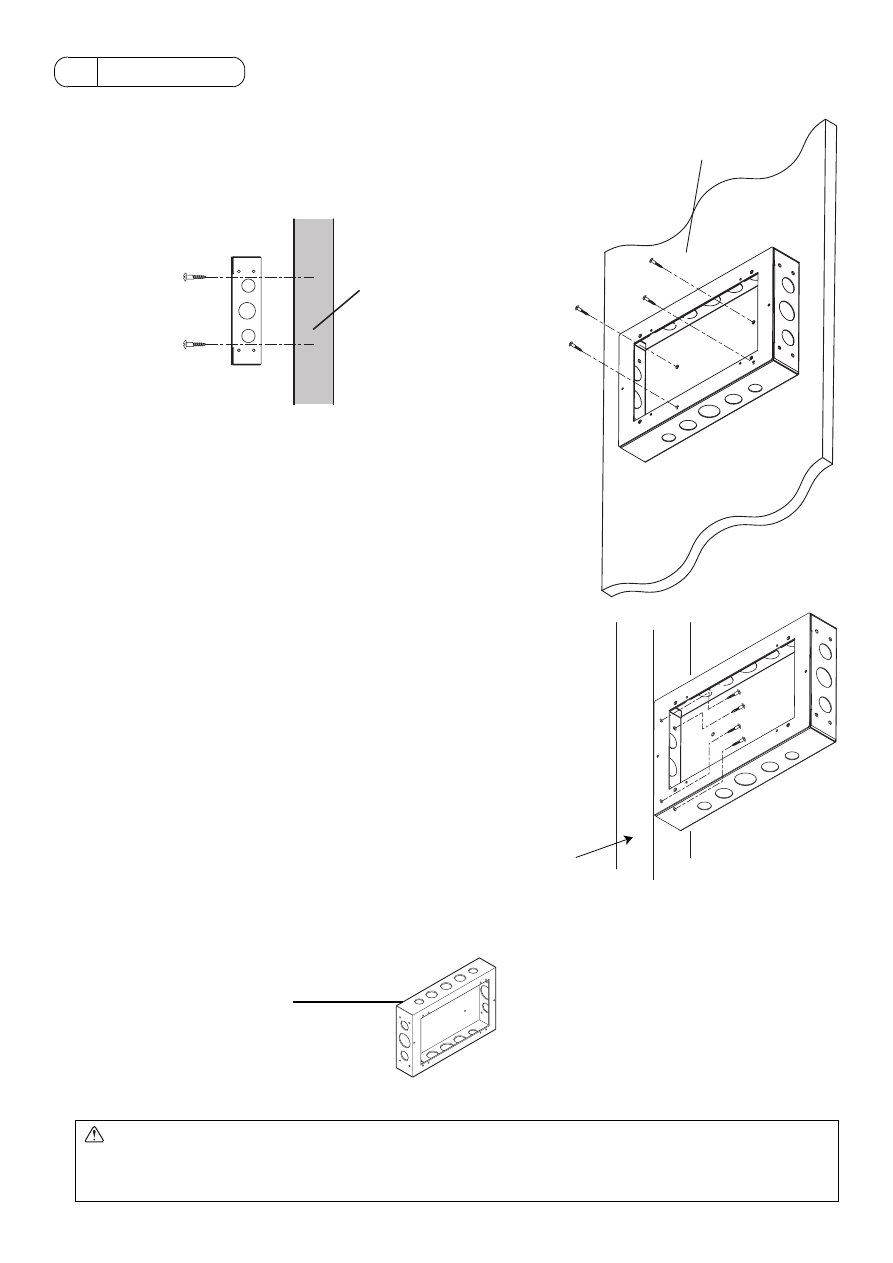
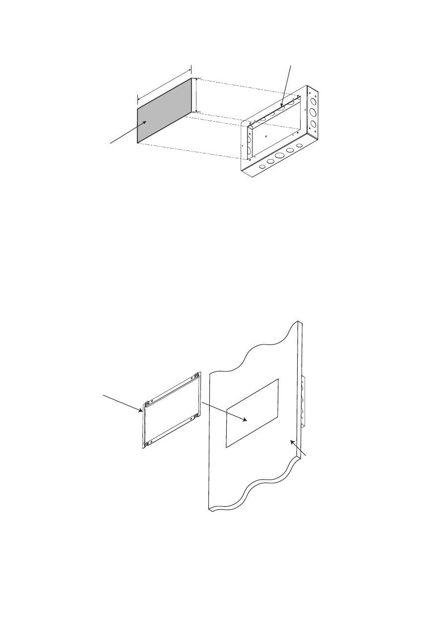
1. Installing the Electric Box (PAC-YG83UTB)
1
Rear installation
To mount the rear of the Electric Box to a structure inside a wall, fix the
Electric Box with the four mounting screws as shown in the right figure.
Select an appropriate type of screws (4 pcs.) to suit the structure type.
Check that the wall is strong enough to support the weight of the Electric Box.
2
Side mounting
Use the four mounting screws to mount the side of the Electric Box to a post
or other building structure.
Select an appropriate type of screws (4 pcs.) to suit the structure type.
Check that the wall is strong enough to support the weight of the Electric
Box.
2. Punch out the knockout holes.
Punch out appropriate knockout holes, depending on how the cables are routed.
5 Installation
CAUTION
Keep the cables from coming in direct contact with the edges of the wire access holes.
If the cables are damaged, they may cause electric shock or fire.
Install a bushing at the end of the conduit tube.
Building structure
Building
structure
Front
Post
Punch out the knockout holes.
(Punch out the appropriate
knockout hole.)
- 5 -
3. Cutting a hole in the wall
Cut a hole for the Electric Box in the wall. Cut a hole along the edges of the Electric Box opening.
The opening should be exactly 278 mm (11 in) [W] × 152 mm (6 in) [H] to allow for a proper installation of the AG-150A.
4. Installing the installation plate
The A type installation plate (supplied with AG-150A) installed by first fitting it in the wall opening, then attaching it to the Electric
Box.
1
Fit the A type installation plate in the wall opening.
278(11)
152(6)
Size of the opening
Cut a hole along the edges of the opening.
Unit: mm (in)
A type installation plate
(supplied with the AG-150A)
Wall
- 6 -
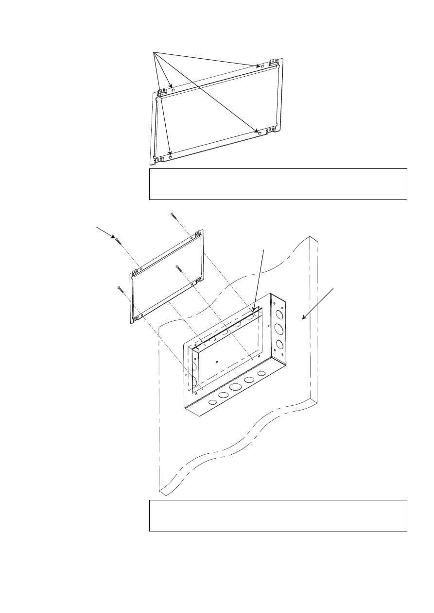
2
Screw the A type installation plate down by putting the M4 flathead screws (supplied with AG-150A) through the mounting
holes on the Electric Box.
Mounting holes
NOTE
If a precise hole is cut out in as shown in Step 3 above, the screw holes on the A type
installation plate will automatically be aligned with the screw holes on the Electric Box.
M4 flathead screws
(supplied with AG-150A)
Mounting holes for the
A type installation plate
Wall
NOTE
Drilling prepared holes (ø3) on the walls will make it easier to screw in the screws.
(* Drill appropriate prepared holes according to the wall material.)
- 7 -
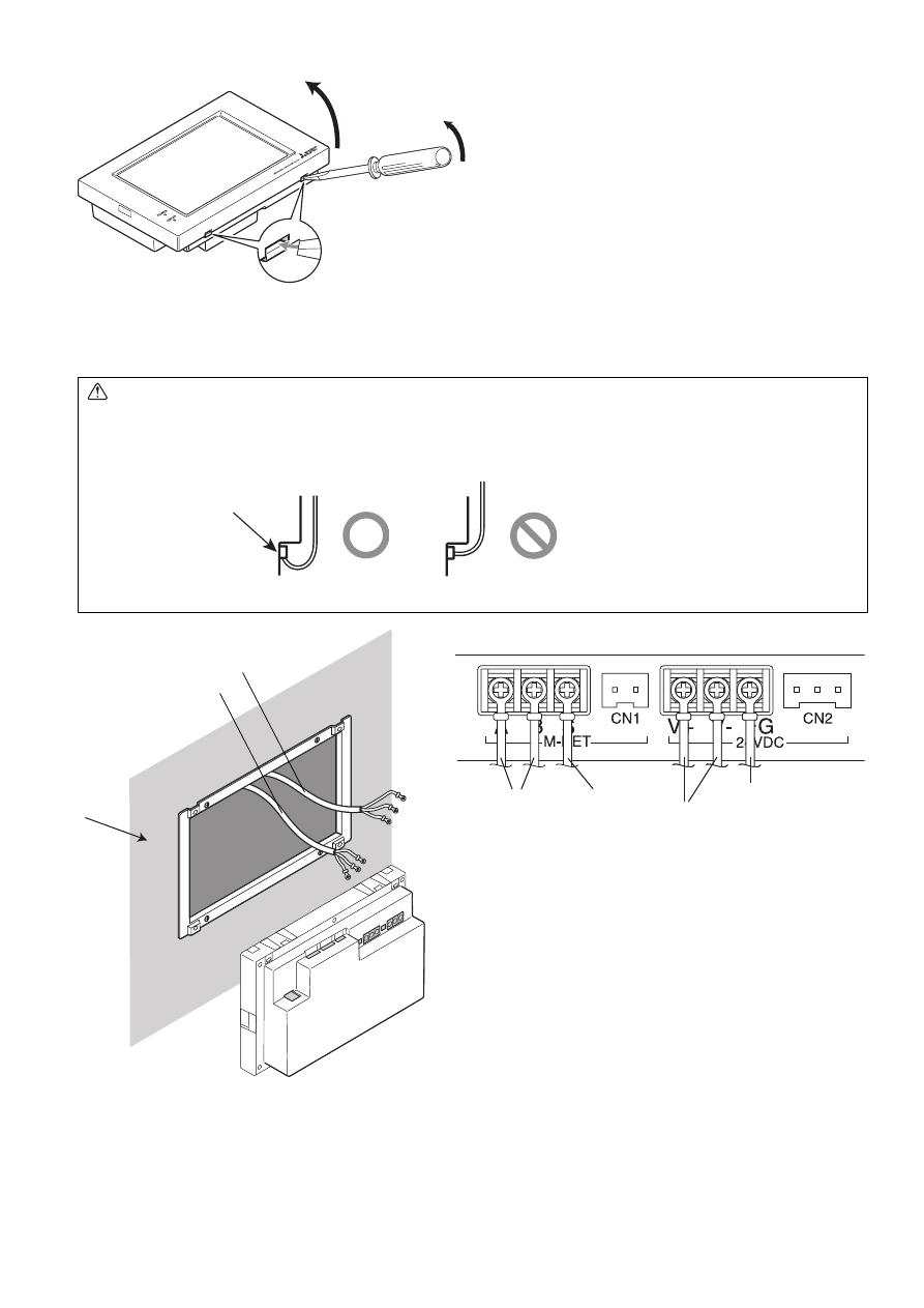
5. Remove AG-150A surface cover.
6. Wiring
Connect the cables to the AG-150A.
Refer to the AG-150A Installation Manual for details.
CAUTION
* Do not put the signal wire and power wire in the same conduit.
* When routing the cable from the top of the controller, let the cable hang down below the connector before connecting it to
the terminal block or connector as shown in the figure below to prevent water from running down the cable and cause
electric shock or fire.
Insert a flat-tip screwdriver in the holes
indicated and move the handle up to
remove the cover.
Terminal block or
connector
Good example
Bad example
Wall
DC Power cable
M-NET transmission cable
M-NET
transmission
cable
DC power cable
Back of controller
shield
Function earthing
(ground) cable
- 8 -
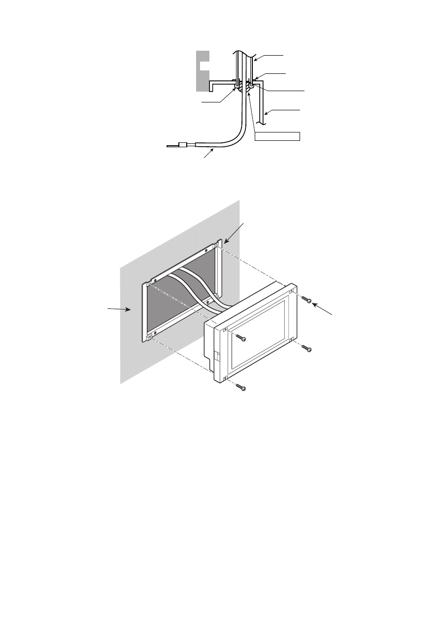
7. Sealing the cable access hole with putty
Install a bushing at the end of a conduit tube, and seal the space in between with putty.
8. Installing the AG-150A
Install the AG-150A with the four M4 round head screws on the A type installation plate.
9. Replace the AG-150A surface cover.
Conduit
Electric box
Bushing
M-NET transmission cable
or DC power cable
Lock nut
Wall
Line lead-in port
Seal with putty
M4 rounded screw
(supplied with AG-150A)
A type installation plate
Wall


HEAD OFFICE: TOKYO BLDG. , 2-7-3, MARUNOUCHI, CHIYODA-KU, TOKYO 100-8310, JAPAN
Authorized representative in EU: MITSUBISHI ELECTRIC EUROPE B.V.
HARMAN HOUSE, 1 GEORGE STREET, UXBRIDGE, MIDDLESEX UB8 1QQ, U.K.
WT05420X01
Printed in Japan
Recycled Paper
Wyszukiwarka
Podobne podstrony:
IM PAC YG81TB WT05422X02 Apr 2009
IM PAC SC51KUA J WT05372X03 Apr 2009
IM PAC IF011B E IF012B E BH79D099H02 GB 09 2009
IM PAC SE51CRB WT03594X05 GB Aug 2009
Kwasy karboksylowe Apr 2009(1)
IM PAC KE07DME WT05243X01 2007
IM PAC SC36NA E(WT04936X01) GB
0300122810 Yale University Press One State Two States Resolving the Israel Palestine Conflict Apr 20
IM PAC SE51CRA WT02699X01 GB 2005
IM PAC SA1ME E RG79V563H01 2007
IM PAC YG66DCA WT04977X01 EN 2007
IM PAC YG63MCA WT04975X01 EN 2007
IM PAC SE55RA E WT02925x01 pd
IM PAC YG60MCA WT04973X01 EN 2007
IM PAC AK31 51BC BG79U439K08 Sep 2010
IM PAC AH125 140 250M H WT04980X02 GB 2007
IM MAC 399IF E SG79Y416H05 Sep 2009
więcej podobnych podstron