Русский
English
Deutsch
Français
Nederlands
Español
Italiano
∂ÏÏËÓÈο
Português
Dansk
Svenska
Türkçe
M-NET Interface
Model
MAC-399IF-E
[FOR INSTALLER]
INSTALLATION MANUAL
[FÜR INSTALLATEURE]
INSTALLATIONSHANDBUCH
[POUR L’INSTALLATEUR]
MANUEL D’INSTALLATION
[FÖR INSTALLATÖREN]
INSTALLATIONSMANUAL
[VOOR DE INSTALLATEUR]
INSTALLATIEHANDLEIDING
[PER L’INSTALLATORE]
MANUALE DI INSTALLAZIONE
[PARA EL INSTALADOR]
MANUAL DE INSTALACIÓN
[PARA O INSTALADOR]
MANUAL DE INSTALAÇÃO
[TIL INSTALLATØREN]
INSTALLATIONSMANUAL
[°π∞ ∞À∆√¡ ¶√À ∫∞¡∂π ∆∏¡ ∂°∫∞∆∞™∆∞™∏]
E°XEIPI¢IO O¢H°IøN E°KATA™TA™H™
[MONTÖR ‹Ç‹N]
MONTAJ ELK‹TABI
[ДЛЯ УСТАНОВИТЕЛЯ]
РУКОВОДСТВО ПО УСТАНОВКЕ
[
]
[
]
2
1. Safety Instructions
• Read all Safety Instructions before using this device.
• This manual contains important safety information. Be sure to comply with all instructions.
• After installing the Interface, provide this Installation Manual to the user.
Instruct users to store their room air conditioner Instruction Manual and Warranty in a safe location.
Warning
(Improper handling may have serious consequences, including injury or death.)
■ Users should not install the Interface on their own.
Improper installation may result in fire, electric shock, or damage/water leaks if the Interface unit falls. Consult the dealer
from whom you purchased the unit or professional installer.
■ The Interface should be securely installed in accordance with the enclosed Installation Instructions.
Improper installation may result in fire, electric shock, or damage/water leaks if the Interface unit falls.
■ The unit should be mounted in a location that can support its weight.
If installed in an area that cannot support the unit, the Interface unit could fall and cause damage.
■ Securely attach the electrical component cover to the Interface unit.
If the electrical component cover of the Interface unit is not securely attached, dust or water penetration could occur,
resulting in a fire or electric shock.
■ Mitsubishi components or other designated components must be used for installation.
Improper installation may result in fire, electric shock, or damage/water leaks if the Interface unit falls.
■ When performing electrical work, adhere to the technical standards regarding electrical equipment and the interior
wiring standards, follow the instructions provided in the Instruction Manual, and be sure to use a dedicated circuit.
Inadequate circuit capacity or improper installation could result in a fire or electric shock.
Contents
1. Safety Instructions .......................................................................................................................... 2
2. Before Installation ........................................................................................................................... 3
3. Mounting the M-NET Interface Unit ................................................................................................ 4
4. Setting the Switches ....................................................................................................................... 5
5. Connecting the M-NET Interface to indoor unit .............................................................................. 7
6. Connecting the M-NET Interface, the Power Supply, and the ME Remote Controller .................... 8
7. Notes Regarding Use ..................................................................................................................... 9
8. Table of Functions Activated from the ME Remote Controller/System Controller ......................... 10
9. Specifications ................................................................................................................................ 10
3
2. Before Installation
2.1. How to Use the M-NET Interface
Caution
When using a packaged air conditioner (city-multi) system remote controller, you cannot register packaged air condi-
tioners and room air conditioners in the same group. In this case, register the Packaged and room air conditioner in
different groups.
■ Functions
Centralized and individual management of M/P/S series using M-NET(*).
* A type of packaged air conditioner control (city-multi)
■ Related Products Sold Separately
• ME Remote Controller
PAR-F27MEA
• Centralized Controller
G-50A
• System Remote Controller
PAC-SF44SRA
• ON/OFF Remote Controller
PAC-YT40ANRA
• Schedule Timer (M-NET)
PAC-YT34STA
• Power supply unit
PAC-SC50KUA
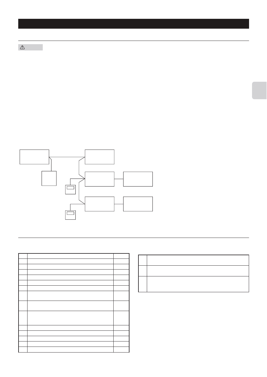
■ Sample of System Configuration (only M/S series outdoor-unit)
Sample configuration of a system using a centralized controller
1 Centralized controller (M-NET)
2 Power supply unit
3 Packaged air conditioner system
4 M-NET Interface
5 Indoor unit
6 ME Remote Controller
* The number of units that can be connected to the
centralized controller (G-50A) is max. 50, including
packaged and room air conditioners. The wiring
from the M-NET Interface to the centralized
controller can have a maximum length of 500 m.
The wiring from the M-NET Interface to the ME
Remote Controller can have a maximum length of
10 m.
For details, see the MELANS Catalog and the
instruction manuals for the Centralized Controller
and ME Remote Controller.
2.2. Accessory
Before installing the device, make sure you have all the necessary parts.
■ Accessory
1
Interface unit (with 5-core connecting cable)
1
2
Wall mounting bracket
1
3
Screws for mounting 2 3.5×12
4
4
Cushioning material (with adhesive)
1
5
Mounting cord clamp (small)
1
6
Mounting cord clamp (medium)
1
7
Mounting cord clamps (large)
2
8
Screws for mounting 5–7 3.5×12
2
* Use when attaching the clamps to the interface unit.
9
Screw for mounting 6 4×10
1
* Use this when mounting the clamps near the M series.
0
Screw for mounting 6 4×16
1
* Use this when mounting cord clamp together with the
parts of M series.
A
Cable ties
5
B
Fasteners (for joining the lead wires)
3
C
Cord clamps for wiring
3
D
Screws for mounting C 3.5×12
3
E
Screws 3.5×12 (spare)
2
■ Items to Prepare at the Installation Site
A
Connecting wires (centralized controller)
Shield wires CVVS/CPEVS
B
Remote control wires (for connecting the ME Remote Controller)
2-core sheath wire 0.3 mm
2
Related parts sold separately
C
* Prepare the necessary number of parts sold separately as needed
for your system.
1
3
2
6
6
4
4
5
5
Use wires which have insulation more than the MAX voltage.
* MAX voltage is defined according to the law of the country where
the interface is used.
* CPEVS; PE insulated PVC jacketed shielded communication cable
* CVVS; PVC insulated PVC jacketed shielded control cable
PE: Polyethylene
PVC: Polyvinyl chloride
4
3. Mounting the M-NET Interface Unit
The M-NET Interface unit should be placed in a location where the 5-core connecting cable from the interface can reach an indoor
unit. Do not extend the 5-core connecting cable. This will cause the device to malfunction.
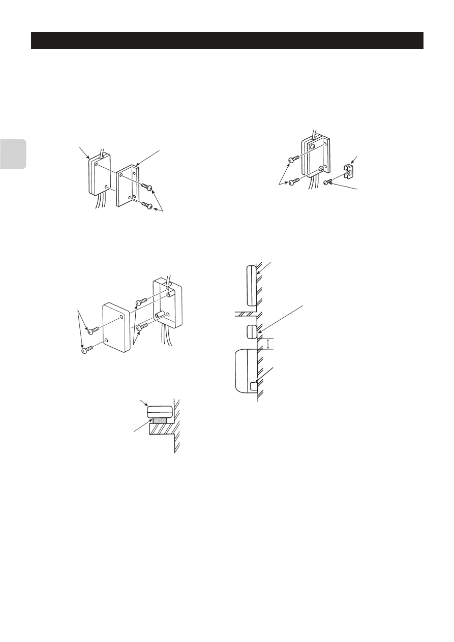
Mount the interface unit securely to a pillar or wall using 2 or more screws.
Screws 3
■ When Using Wall Mounting Bracket 2
1
Attach the wall mounting bracket 2 to the interface unit 1
using 2 screws 3.
Screw D
Interface unit 1
Wall mounting
bracket 2
Screws 3
Cord clamp for
wiring C
■ When Mounting Directly to a Wall
Mount the case of the interface unit 1 to the wall using the
screws 3.
* When mounting the interface unit 1 using a cushioning
material 4, be sure to mount it in a location where it will not
fall.
Interface unit 1
mounting screws
Screws 3
Cushioning material 4
Interface unit 1
2
Mount the unit to a pillar or wall using 2 screws 3.
When mounting the interface unit 1 inside a ceiling
or wall, install an access door to facilitate mainte-
nance.
When the interface unit 1 is mounted
above an indoor unit, it should be
positioned 40 mm or more away from the
unit to ensure that ceiling grills can be
removed.
40 mm or more
Attach the 5-core connecting cable of the interface unit
1 here. Store extra 5-core connecting cable in the
ductwork space behind the indoor unit.
* If there is any slack in the 5-core connecting cable,
use a fastener B to keep it in place.
5
4. Setting the Switches
If the system is not configured correctly, the unit will not function properly. You may be unable to control the functions of the indoor
unit from the System Controller/ME Remote Controller or functions not available on the indoor unit could appear on the System
Controller/ME Remote Controller display. You should therefore ensure that the system is properly configured before connecting
the power supply.
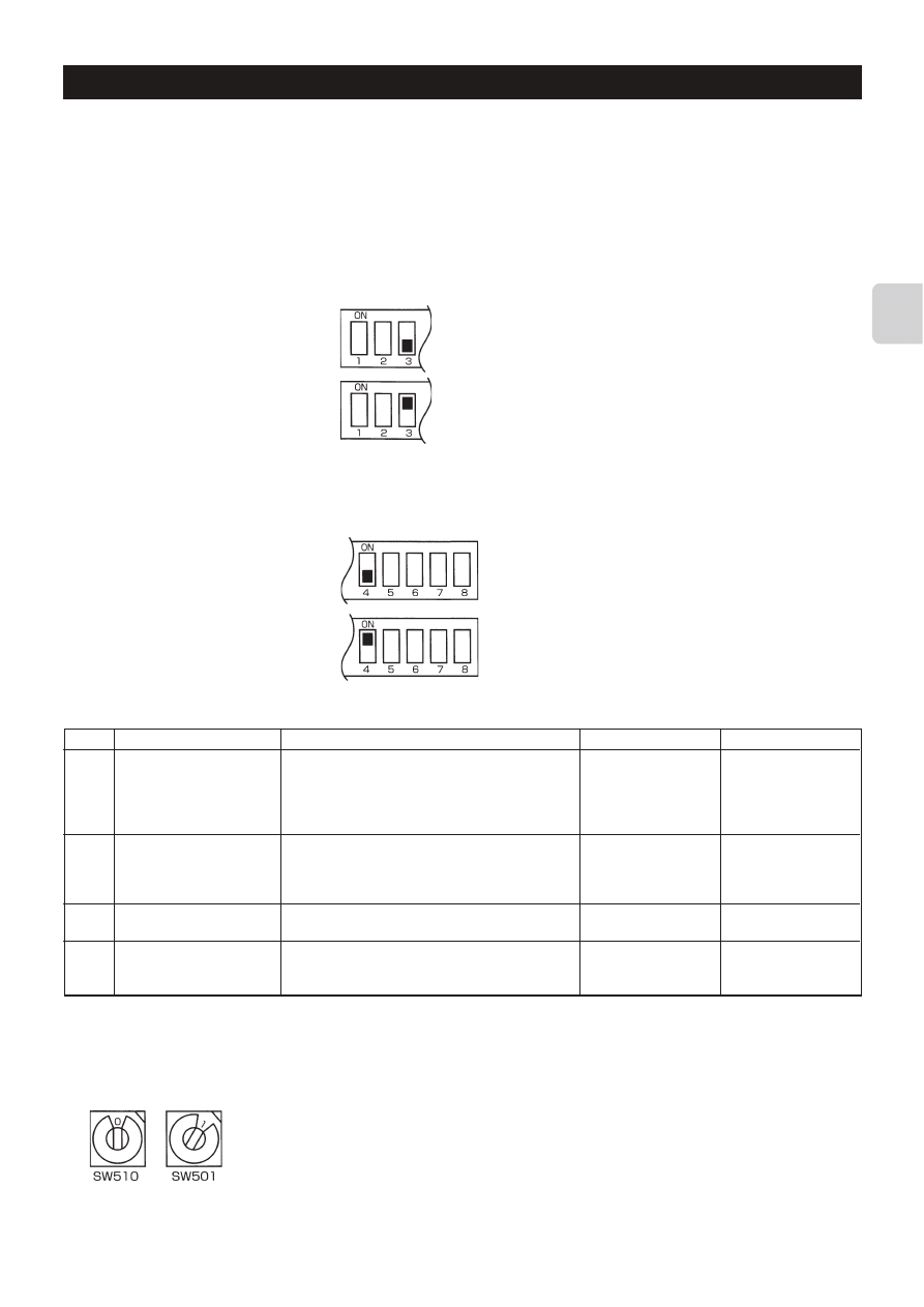
■ SW500 No. 1, No. 2 - Not in use
These should be set to OFF (if set to ON, the device will not communicate properly with the System Controller).
■ SW500 No. 3 - Power On/Off Settings
This setting indicates whether the indoor unit should be turned off or on when power is supplied to the indoor unit or M-NET
Interface.
Turn on with power No
[Unit remains off when the power is supplied.]
■ SW500 No. 4 - Availability of purifier or fan mode
If there is no “Purifier” button on the wireless remote control, and if the word “Fan” does not appear when the “Mode” button is
pressed, the purifier and fan modes are not available (set to OFF).
Turn on with power Yes
[Unit turns on when the power is supplied.]
Has a purifier or fan mode
Does not have a purifier or fan mode
ON
Does have an auto op-
eration mode
Does not have a fan os-
cillation setting
Does not have a fan di-
rection setting
Cooling unit only
■ SW500 No. 5–No. 8 - M series Function Check
Function description
Availability of automatic op-
eration mode (a mode that al-
lows the air conditioner to de-
termine whether to select
cooling or heating).
Availability of a fan oscillation
setting
Availability of a fan direction
setting
Availability of a heating mode
SW500
No. 5
No. 6
No. 7
No. 8
How to check a function
If “Auto” is not displayed when you push the “Mode” but-
ton on the wireless remote control, the auto operation
mode is not available (OFF).
If “Oscillate” is displayed when you push the “Fan Direc-
tion” button on the wireless remote control, the fan os-
cillation setting is available (OFF). (If there is no “Fan
Direction” button, the setting is OFF.)
If there is a “Fan Direction” button on the wireless re-
mote control, the fan direction setting is available (OFF).
If “Heat” appears when you push the “Mode” button on
the wireless remote control, the unit is a model that of-
fers both cooling and heating (OFF).
OFF
Does not have an auto
operation mode
Has a fan oscillation set-
ting
Has a fan direction set-
ting
Dual cooling and heating
model
■ SW510, SW501 - Address settings
Specifies the address settings for centralized management (address settings can be set from 01–50).
SW510 sets the 10s position of the address and SW501 sets the 1s position of the address.
For example, to set a unit to the address 25, set SW510 to “2” and SW501 to “5”.
1s position
Self-Address
10s position
6
DM00J805B
DIP
(1)
1
24
40
64
A
IC570
LD501-1
LD501-2
LD503-1
LD503-2
CST50
CST51
1
8
CN501
1
9
CN502
1
11
CN503
4
1
CN504
L570
L571
1
5
CN127
C500
1
5
CN560
C570
C571
C572
C573
C576
LD502-1
LD502-2
R5A1
R5A2 R5A3 R5A4 R5A5
R5A6 R5A7 R5A8
R5B1 R5B2 R5B3
R5B4 R5B5
R5B6
R5B7 R5B8
R5C1
R5C2
R5C3
R5C4
R5C5
R5C6
R5D1
R5D2
R5D3
R5D4
R5D5
R5D6
R5D7
R5D8
R5E1
R5E2
R5E3
R5E4
R5E5
R5E6
R5E7
R5E8
R5F1
R5F2
R5F3
PG
R5F4
R5F5
R5F6
R5F7
R5G1
R5G2
R5G3
R5G4
R5G5
R5G6
Q560
R500
Q561
R501
R502
R503
R504
R505
R506
R507
R508
R509
R510
R511 R512 R513 R514 R515 R516 R517
R518
R51A
PC560
PC561
R535
R536
C502
C503
R540
R541
C510
C511
C512
C513
R550
C514
R551
R562
R563
R564
R565
R582
R583
R584
R585
C560
D500
C574
IC500
IC501
52
40
1
13
14
26
27
39
IC510
C575
C501
Pb Solder
DM00J805B
A
DIP
(2)
1
1
A1
A2
B2
B1
S
M-Net2
M-Net1
1
10
M-NET Address
Q520
Q521
ON
SW500
SW501
SW510
ON
SW520
TB520
TB521
1
8
CN511
1
9
CN512
1
11
CN513
4
1
CN514
C520
C521
C522
C523
C524
C525
PG
ZD520
ZD521
ZD522
ZD523
R520
R521
R522
R523
R524
R525
R526
R527
R528
C526
C527
C528
1
11
12
22
23
33
34
44
IC520
PG
Pb Solder
SW500
SW510
SW501
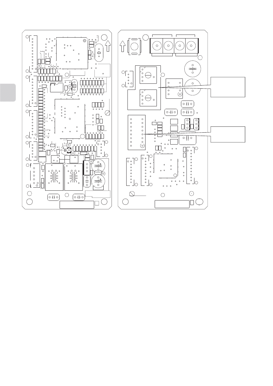
■ Position of SW500, SW501, SW510
7
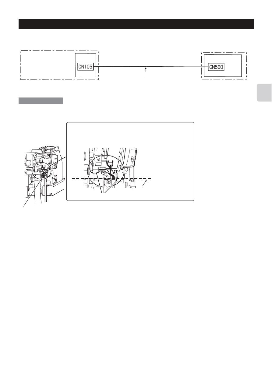
5. Connecting the M-NET Interface to indoor unit
Connect the M-NET Interface board to the indoor control board.
Connect the 5-core connecting cable that comes
with the M-NET Interface unit to the connector
CN105 on the indoor control board.
Indoor unit
Indoor control board
Interface unit 1
• 5-core connecting cable connected to the Indoor unit should be mounted on the Indoor unit.
If the 5-core connecting cable is not securely mounted, the connector may detach, break, or malfunction.
• Set the interface dip switch (SW500–502) settings before turning on the power.
• If the interface dip switch (SW500–502) settings are not set correctly, the system will not function properly.
Hook
The range in which the thin part
of the connecting cable is
secured.
2 If there is excess thin part of the connecting cable, lay it out
using hooks as shown in the figure.
The thin part of the cable should be secured above the dotted
line indicated in the figure.
1 Attach a mounting cord clamp 5–6 provided with the parts prepared at the installation site to the thick
part of the connecting cable, and fix it with a screw 9.
3 Close the cover of the indoor control P.C. board. Reinstall the front panel and the lower right corner box.
Dotted line (The position of the
edge face of the indoor control
P.C. board.)
Connection example
8
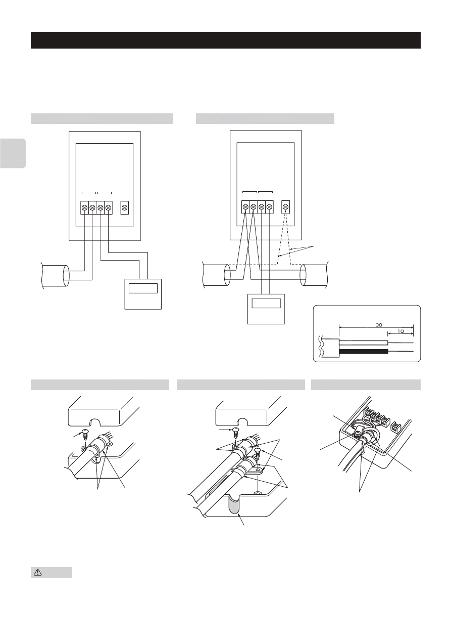
6. Connecting the M-NET Interface, the Power Supply, and the ME Remote Controller
• When connecting the unit to a system controller or ME Remote Controller, connect the transmission line of the M-NET to the
control signal terminal.
Connect the 2-core connecting wire A to A1/B1 or A2/B2.
• Cross the shield portion of each connecting wire using the S terminal only when cross wiring the connecting wires.
• When connecting the connecting wire A and the ME Remote Controller connecting wires B to the terminal board, there is no
need to worry about polarity.
When the connecting wire A is not cross-wired
When the connecting wires A are cross-wired
1 Shield
2 Connecting wires A
(M-NET transmission wire)
3 ME Remote Controller
(only when needed)
Bare wire size
• After the wiring is completed secure the ires with the cord clamp (large) and the cable ties.
1 Screws 8
2 Cord clamp (large) 7
3 Cord clamp (small) 5
Caution
• Electrical work should be performed in accordance with the Technical Standards Regarding Electrical Equipment
and the Interior Wiring Standards.
• Connecting wires and remote control wires should be located as far away from other electrical wiring as possible.
Placing them too closely together could cause a malfunction.
When the connecting wires A are cross-wired
A1 B1 A2 B2
S
2
3
A1 B1 A2 B2
S
2
2
3
1
When using the ME remote controller
When the connecting wire A is not cross-wired
1
4
2
1
5
4
1
2
4
3
1
4
2
4 Cable ties A
5 Cut with nippers at the notches.
Make sure the cut surface is free of any burr so that the
connecting wires do not get damaged.

9
7. Notes Regarding Use
Please read this information carefully before attempting a test run.
The following control information should be thoroughly explained and provided to the users of this device. (Please provide these
instructions to the user once the installation is complete.)
* This M-NET Interface operates M/P/S Series using the controls of a packaged air conditioner (city-multi), but there are several
limitations imposed as a result of the functional differences between M/P/S Series and packaged air conditioners.
1. When operating the system using a system controller or ME Remote Controller, these operations will not appear on the
display of the wireless remote controller.
2. Functions available only on M series (e. g. ECONO COOL) cannot be operated using the ME Remote Controller/System
Controller. When these functions are operated using the wireless remote controller that came with M series, the operated
using the wireless remote controller that came with M series, the operation will not appear on the display of the ME Remote
Controller/System controller.
3. Functions that are available on the ME Remote Controller/System Controller but that are not available on the M/P/S series
can be operated by switching to a predetermined separate operation mode. (See the “Table of Functions Activated from the
ME Remote Controller/System Controller.”)
4. Functions that are available on the remote controller of the M/P/S series but are not available on the ME Remote Controller/
System Controller will produce a predetermined display. In this case, the actual operation and the display may differ. (If the
fan speed is automatically set using the remote controller that came with the M/P/S series, the setting “High” will appear on
the ME Remote Controller/System Controller. Likewise, if the fan direction is set to automatic, the setting “Downward Air
Flow 80%” will appear on the ME Remote Controller/System Controller.)
5. Because the temperature range of the M/S series is broader than the ME Remote Controller/System Controller, when the
M/S series is set to lower than 17°C or higher than 30°C, the temperature display on the ME Remote Controller/System
Controller will show the minimum or maximum temperature that can be set. (For example, even if the room air conditioner
is set to cool a room to 16°C, the display on the ME Remote Controller/System Controller may read “17°C.”)
The M/S series operates according to the room temperature detected by the M/S series unit.
6. Timer operations should be set using only the remote controller that came with the M/P/S series or the ME Remote
Controller/System Controller. If both are used to set the timer to the same time, the timer will not function properly.
7. When the timer is set using the remote controller that came with the M/P/S series, the timer information will not be dis-
played on the ME Remote Controller/System Controller.
8. If the timer is set using the ME Remote Controller/System Controller, the timer set using that device will not be cancelled
even if the unit is turned off using the remote controller that came with the M/P/S series.
9. When manual operations using the system controller are prohibited, the remote controller that came with the M/P/S series
will not function, but the beeping sound that is emitted when it is operating normally will still sound.
10. To clear an error message from the display of the ME Remote Controller/System Controller, briefly turn off the unit using
the ME Remote Controller/System Controller or the remote controller that came with the M/P/S series. (The error display
on the air conditioner unit may be cleared automatically, but it will not clear from the ME Remote Controller/System Control-
ler until the unit is turned off.)
11. The room temperature sensor installed in the ME Remote Controller cannot be used.
10
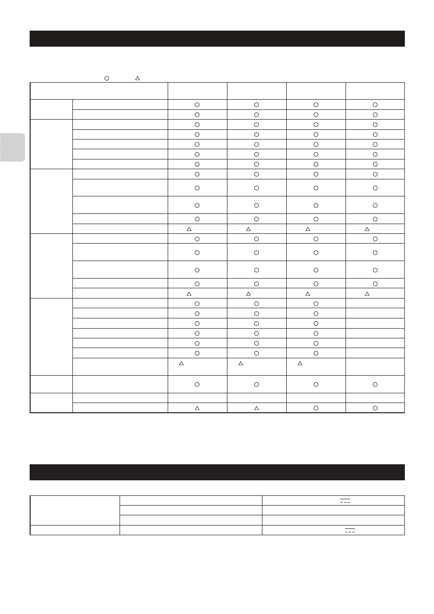
8. Table of Functions Activated from the ME Remote Controller/System Controller
Functions operated from the wireless remote controller that came with M/P/S series.
[Symbol]
: Available/ : Available with limitations on the display/×: Non-available/–: Non-applicable (no functions)
*1: Functions that are not available on M/P/S series (MAC-399IF) cannot be performed.
The display on the M-NET side shows the words in the parentheses.
(Symbols may be used instead of the words.)
*2: The display does not appear on the wireless remote controller.
ME remote
controller
(High)
(High)
(Bottom flow
Position3)
×
Power On (Operation)
Power Off (Stop)
Auto operation (Operation)
Manual Cool (Cool)
Manual Heat (Heat)
Manual Dry (Dry)
Air-purifying (Fan)
Low (First: Low)
Med. (Second: Medium2)
Med. (Third: Medium2)
High (Third: Medium1)
High (Forth: High)
Super high (Forth: High)
AUTO
Low (First: Low)
Med. (Second: Medium)
Med. (Second: Medium1)
High (Third: Medium)
Med. (Second: Medium2)
Super high (Forth: High)
AUTO
Position1 (Horizontal)
Position2 (Bottom flow Position2)
Position3 (Bottom flow Position3)
Position4 (Vertical)
Position5 (Vertical)
Swing
AUTO
16°C–31°C
Timer display
Inlet temp. (10–38°C) *2
9. Specifications
Input voltage
Power consumption
Input current
Input voltage
Air conditioner side
M-NET side
12 V
0.6 W
0.05 A
17–24 V
Functions *1
On/Off
Mode
Fan speed
(MSZ, S, P)
Fan speed
(MFZ)
Air direction
Set
temperature
Monitor
G-50A
(High)
(High)
(Bottom flow
Position3)
×
BACnetl/F
(High)
(High)
(Bottom flow
Position3)
×
LM-AP
(High)
(High)
—
—
—
—
—
—
—
×
Wyszukiwarka
Podobne podstrony:
IM MAC 397IF E SG79Y415H01 EN
eu can draft chapter ipr sep 2009
IM PAC YG81TB WT05422X02 Apr 2009
IM PAC YG83UTB WT05420X01 Apr 2009
IM MAC 821SC E SG79Y547H02 2007
BWE09240 PAC KE91 95TB E Sep 2009
IM PAR21MAA WT05598X01 GB 04 2009
IM MXZ 4A80VA SG79Y463H01
IM PAC SC51KUA J WT05372X03 Apr 2009
1438427751 State University of New York Press Heideggers Neglect of the Body Sep 2009
Biogasanlagen im EEG 2009
2009 5 SEP Endoscopy
IM jednolity tekst 2009
ZESPÓŁ SZKÓŁ PONADGIMNAZJALNYCH NR l IM, 12.PRACA W SZKOLE, ZSG NR 1 2008-2009
Materialy do seminarium IM 2009 10 czesc I
Biogasanlagen im EEG 2009
IM PCFY P40 125VKM E RG79D452H01 GB 01 2009
więcej podobnych podstron