English
[For Retailers and Contractors]
INSTALLATION MANUAL
MA & CONTACT TERMINAL Interface
Model
MAC-397IF
2
1. Safety Instructions
• Read all Safety Instructions before using this device.
• This manual contains important safety information. Be sure to comply with all instructions.
• After installing the Interface, provide this Installation Manual to the user.
Instruct users to store their room air conditioner Instruction Manual and Warranty in a safe location.
Warning
(Improper handling may have serious consequences, including injury or death.)
■ Users should not install the Interface themselves.
Improper installation may result in fire, electric shock, or damage/water leaks if the Interface unit falls. Consult the retailer or
specialty store where you purchased the unit for referral to an installer.
■ The Interface should be securely installed in accordance with the enclosed Installation Instructions.
Improper installation may result in fire, electric shock, or damage/water leaks if the Interface unit falls.
■ The unit should be mounted in a location that can support its weight.
If installed in an area that cannot support the unit, the Interface unit could fall and cause damage.
■ Securely attach the electrical component cover to the Interface unit.
If the electrical component cover of the Interface unit is not securely attached, dust or water penetration could occur,
resulting in a fire or electric shock.
■ Mitsubishi components or other designated components should be used for installation.
Improper installation may result in fire, electric shock, or damage/water leaks if the Interface unit falls.
■ When performing electrical work, adhere to the Technical Standards Regarding Electrical Equipment and the Inte-
rior Wiring Standards, follow the instructions provided in the Instruction Manual.
Improper installation could result in a fire or electric shock.
Contents
1. Safety Instructions .......................................................................................................................... 2
2. Before Installation ........................................................................................................................... 3
3. Connecting the Remote Control Interface to the RAC .................................................................... 4
4. Connecting the remote control interface with each system ............................................................ 5
5. Dip Switch Details ........................................................................................................................... 9
6. Test Run (Check Operations) ....................................................................................................... 12
7. Mounting the Remote Control Interface Unit ................................................................................ 12
8. Specifications ................................................................................................................................ 13
About the Remote Control Interface
The Remote Control Interface is not compatible with all RACs.
Before installation, confirm that your RAC is compatible with this device.
3
2. Before Installation
2.1. How to Use the Remote Control Interface
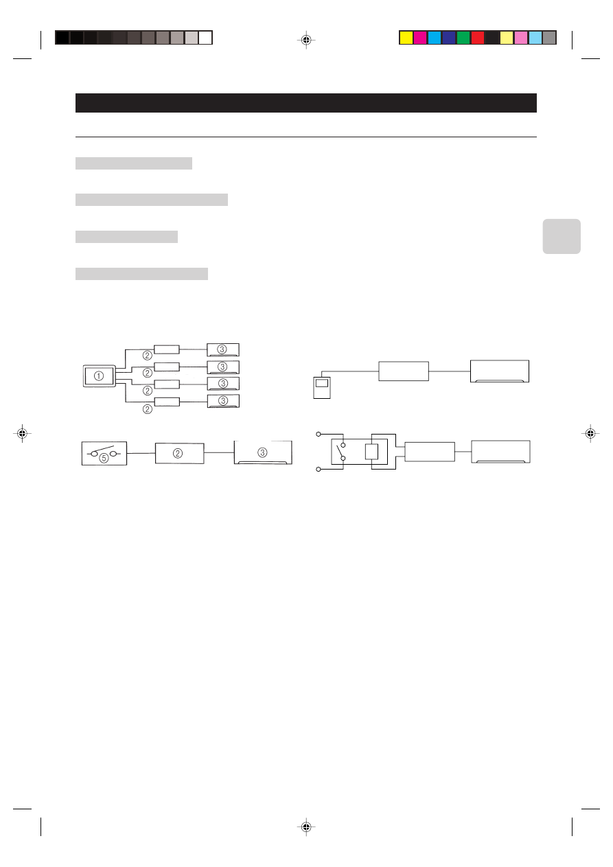
■ Sample System Configuration
■ Functions
Centralized control (Fig. 2-1)
You can turn multiple air conditioners on and off from one location. (MAC-821SC-E (8-Room))
Use as wired remote control (Fig. 2-2)
You can use the MA remote controller as a wired remote control. (PAR-20MAA)
Remote control (Fig. 2-3)
You can turn an air conditioner on and off by connecting the ON/OFF contact point from a remote location.
Status indicator output (Fig. 2-4)
You can drive control the relay with either of the on/off or error/ok status output signals.
4
2
3
5
6
7
2
3
1 Centralized controller
2 Remote control interface
3 RAC
4 MA remote controller
Fig. 2-1
Fig. 2-2
Fig. 2-3
Fig. 2-4
5 Contact point
6 Relay
7 Coil
8 Breaker
4
2.2. Parts
Before installing the unit, make sure that you have all the necessary parts.
■ Accessory
1
Interface unit
1
2
Wall mounting brackets
1
3
Screws (black) for mounting 2 3.5
× 12
4
4
Cushioning material (with adhesive)
1
5
Mounting cord clamp (small)
2
6
Mounting cord clamp (medium)
2
7
Mounting cord clamp (large)
2
8
Screws (black) for mounting 5–7 3.5
× 12
* Use when attaching the clamps to the interface unit
2
9
Screws for mounting 5–7 4
× 10
* Use when mounting the clamps on or near the RAC
1
Screws for mounting 5–7 4
× 16
1
0
* Use when mounting the clamps and electrical wire
mounting bracket
A
Fasteners (for joining the lead wires)
5
B
Wiring cord clamp
5
C
Screws (black) for mounting B 3.5
× 12
5
D
Screws (black) for mounting the interface case 3.5
× 12
2
E
Lead wires (6)
1
■ Items to Prepare at the Installation Site
A
Signal wire extension cable (if necessary)
Shield wiring CVVS/CPEVS
B
Switch, relay, coin timer, etc. (if necessary)
* Please use products with supplementary insulation.
Related products sold separately
C
* Prepare the necessary number of parts sold separately as needed
for your system.
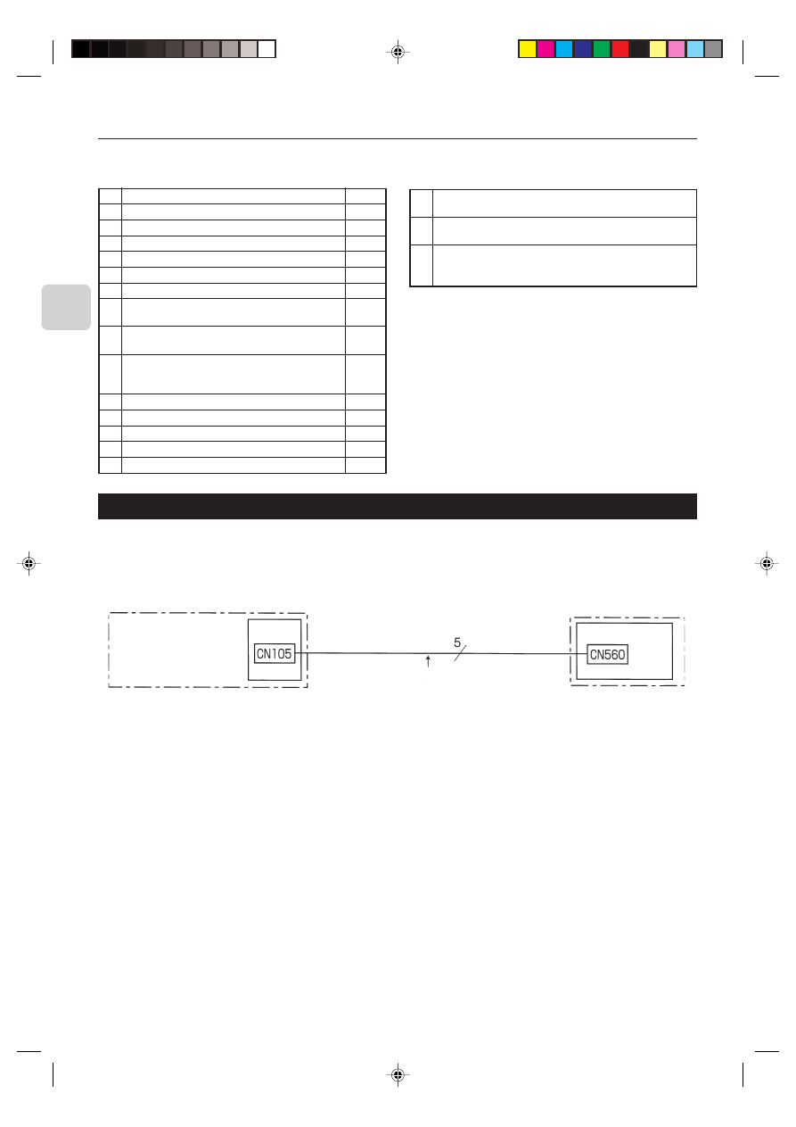
3. Connecting the Remote Control Interface to the RAC
• Connect the remote control interface unit and the RAC indoor control board using the connecting cable that came with the
remote control interface.
• Extending or shortening the connecting cable that comes out of the remote control interface may cause it to malfunction. Also,
keep the connecting cable as far as possible away from the electrical wires and ground wire. Do not bundle them together.
Connect the connecting cable that comes with the
remote control interface unit to the connector
CN105 on the indoor control board.
RAC
Indoor control board
Interface unit 1
* CPEVS; PE insulated PVC jacketed shielded communication cable
* CVVS; PVC insulated PVC jacketed shielded control cable
PE: Polyethylene
PVC: Polyvinyl chloride
5
4. Connecting the remote control interface with each system
(For details on each system, see the relevant instruction manual.)
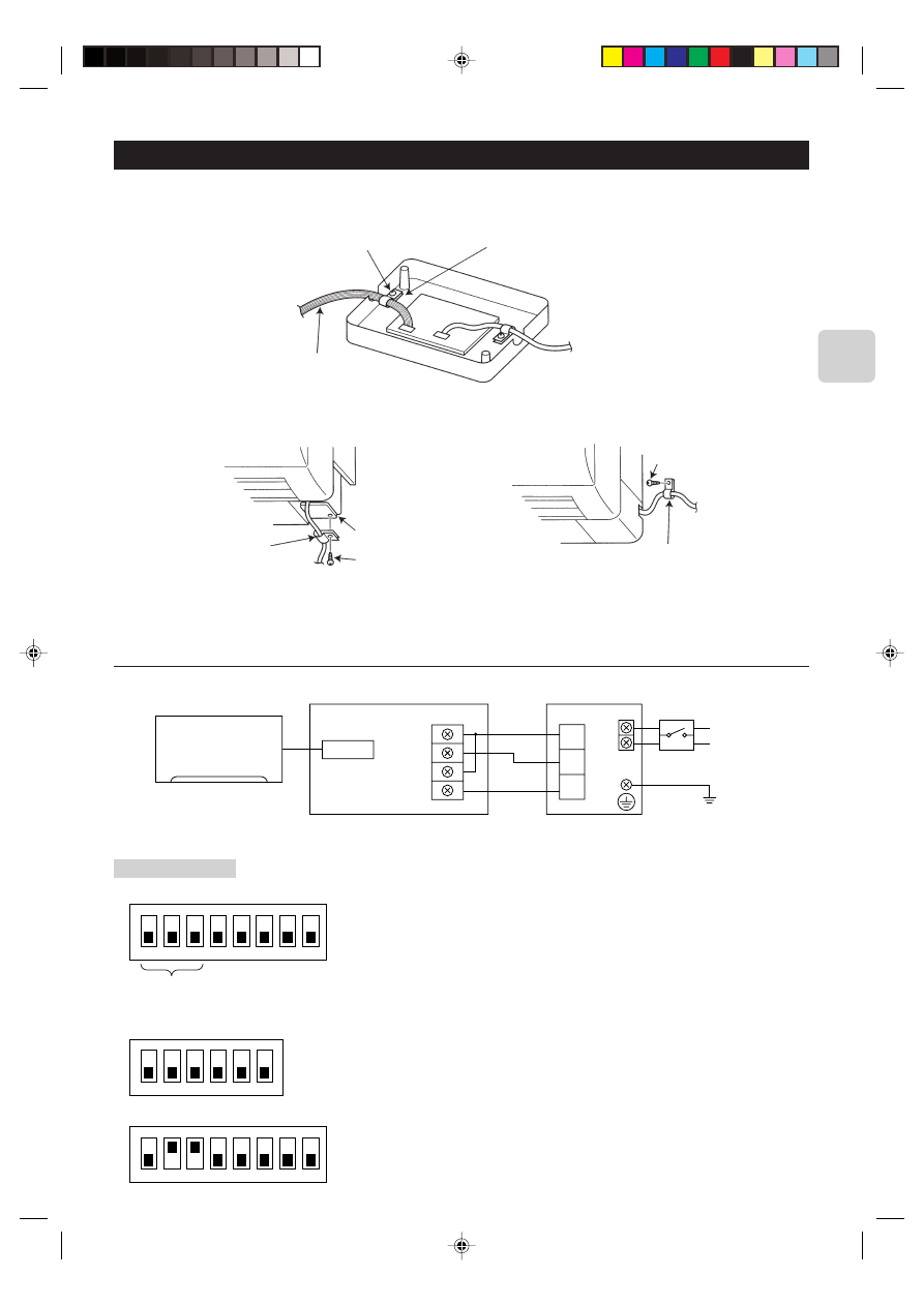
• Replace the interface unit 1 mounting cord clamp with a supplied mounting cord clamp 5–7 based on the thickness of the
connecting cable used for each system.
Interface unit 1 mounting cord clamp or mounting
cord clamps 5–7
Mounting screws (black) 8 3.5
× 12
Connecting cable for each system
Mounting cord clamp 6
Mounting cord clamp 6
Electrical wire mounting
bracket
Mounting screws 0 4
× 16
Mounting screws 9 4
× 10
• The cables connected to the RAC should be mounted on or near the RAC.
If the connecting cable is not securely mounted, the connector may detach, break, or malfunction.
• Set the interface dip switch (SW500–502) settings before turning on the power.
• If the interface dip switch (SW500–502) settings are not set correctly, the system will not function properly.
4.1. Centralized Control (When Connecting to a Centralized on-off remote Controller)
Power supply
~/N 220-240 V
50/60 Hz
CN560
TB571
D
C
M
TC1
TC2
TM1
TM2
RAC
Interface unit 1
* Centralized on-off
remote controller
*Breaker
Ground
Dip switch settings
■ SW500
■ SW501 and SW502 do not have to be set.
ON
1
2
3
4
5
6
7
8
* Refer to the installation manual of centralized on-off remote controller.
ON
1
2
3
4
5
6
ON
1
2
3
4
5
6
7
8
SW501
SW502
Setting required
6
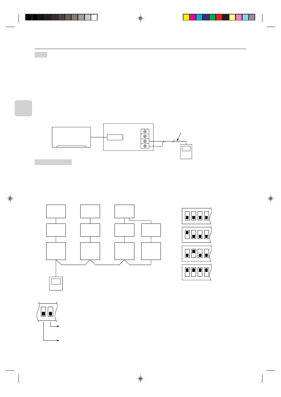
4.2. Use as a Wired Remote Control (Using the MA Remote Controller)
Note:
1. Be sure the Auto Heating/Cooling Display Setting on the MA remote controller is set to OFF before use.
• For information on how to set the Auto/Heating Cooling Display Setting, see the MA remote controller instruction
manual.
• The actual operating status of the unit may differ from what is shown on the remote controller display.
2. A test run cannot be initiated using the test run switch on the MA remote controller.
3. The horizontal panes on the unit cannot be operated using the louver switch.
4. A timer set using a wireless remote control will not be displayed on the MA remote controller.
5. If operations are performed using the MA remote controller while a timer set using a wireless remote control is
running, the timer operation will be canceled.
6. The range of room temperature indication is between 10°C and 38°C.
The MSZ-GA Series and MSZ-FA Series have three fan speed settings (High, Med., Low).
CN560
TB580
2
1
2
A
B
RAC
Remote control cord that came with
the MA remote controller
Dip switch settings
■ SW500 does not have to be set.
■ SW501:
SW501- No. 1–4: Refrigerant address
• Set this switch when multiple indoor units (and remote control interfaces) are connected to a single MA remote controller.
• Always start the refrigerant address at “0”.
• Even when connecting multiple outdoor RAC units, set a different refrigerant address for each indoor unit.
1
1
2
3
3
3
3
4
4
4
4
5
ON
1
2
3
4
ON
1
2
3
4
ON
1
2
3
4
ON
1
2
3
4
1 Outdoor unit
2 RAC multiple outdoor units
3 Indoor unit
4 Interface
5 MA remote controller
Refrigerant
address
0
1
2
15
SW501- No. 5–6
ON
5
6
Only turn this ON when the indoor units in the same group include models where the MA remote controller and
indoor unit are directly connected.
Set them to ON only when using the room temperature sensor installed in the MA remote controller.
* This can be switched when an accurate room temperature cannot be detected by the air conditioner unit.
MSZ-GA and MSZ-FA Series models do not have a room temperature sensor on their MA remote controllers.
(Some RAC models will not allow the use of the MA remote controller room temperature sensor.)
No. 5 and 6 should normally be set to OFF.
Under the following conditions, however, they should be switched to ON.
Interface unit 1
↓
Refrigerant
adress “0”
Refrigerant
adress “1”
Refrigerant
adress “2”
Refrigerant
adress “3”
MA remote controller
(PAR-21MAA)
* PAR-20MAA cannot be used
with this interface.
7
■ SW502:
• Set this switch based on the functions of the RAC connected to the interface.
• See the Page 12 table and set the switch after checking the functions using the wireless remote control that came with the
RAC.
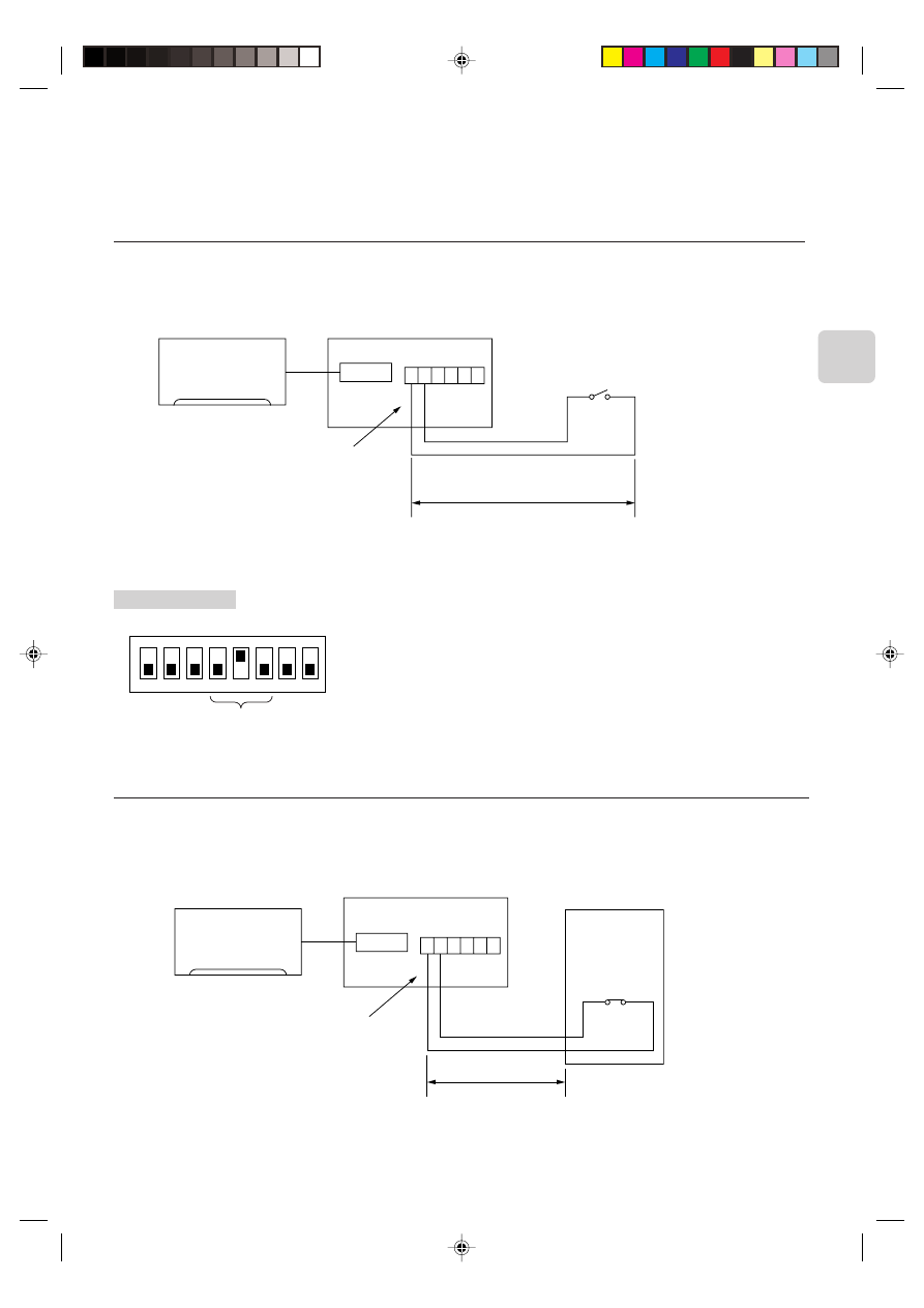
4.3. Remote Control (Turning an RAC On and Off from the Contact Point)
• You can turn an RAC on and off using an on/off switch like a light switch.
• Connect the supplied lead wires (6) E to the connector CN591 on the interface board.
• Wire the remote control components, including the switches, at the installation site.
• Please use extension cords with reinforced insulation.
CN560
CN591
1 2 3 4 5 6
100 m max.
RAC
Interface unit 1
Lead wires (6) E
Switch (contact point a)
(about 10 mA)
Dip switch settings
■ SW500
* When the switch contact point is closed (ON), the air conditioner will turn on, and when the switch contact point is open (OFF),
the air conditioner will turn off.
ON
1
2
3
4
5
6
7
8
Setting required
■ SW501 and SW502 do not have to be set. Both should be set to OFF.
4.4. Coin Timer Use (Restricting RAC Operations from the Contact Point)
• You can use a coin timer or light switch to ensure that an RAC will not operate.
• Connect the supplied lead wires (6) E to the connector CN591 on the interface board.
• Wire the remote control components, including the coin timers or switches, at the installation site.
• Please use extension cords with reinforced insulation.
CN560
CN591
1 2 3 4 5 6
RAC
Interface unit 1
Lead wires (6) E
Contact point a
(about 10 mA)
* When the contact point is open, the unit will turn off and will not be operable from the remote control.
When the contact point is closed, the unit will turn on and will be operable from the remote control.
Coin timer
Extend the cord using the extension cord A
at the installation site.
100 m max.
Extend the cord using
the extension cord A at
the installation site.
8
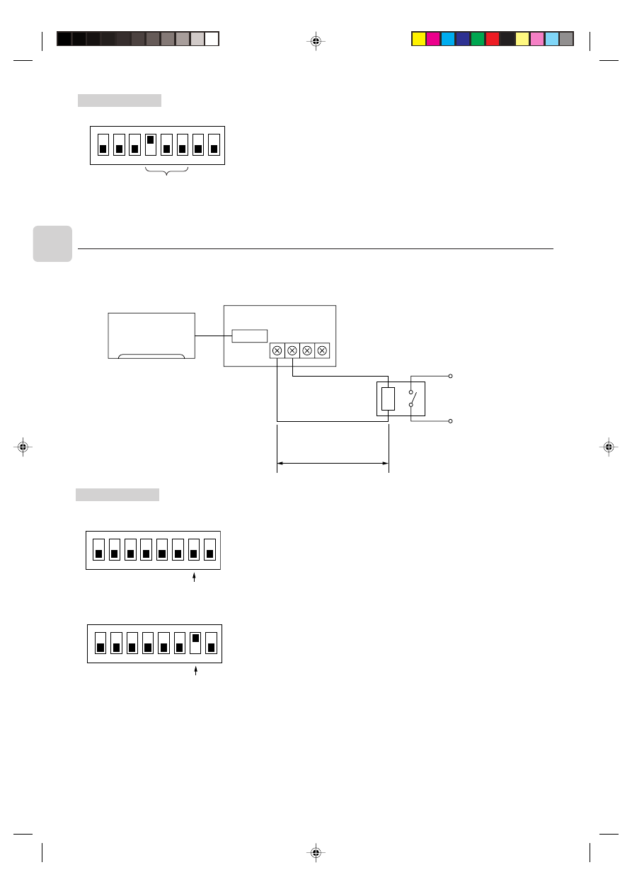
4.5. Status Signal Output Using the Relay
• You can set the external relay to ON/OFF based on whether the RAC is set to either on/off or error/ok.
• Set up and wire the relay and extension cables at the installation site.
• Please use relays with reinforced insulation.
CN560
TB580
1
2
A
B
RAC
Interface unit 1
Relay
(coil rating of DC12 V 75 mA or less)
Dip switch settings
■ SW500
1. When outputting the RAC on/off
2. When outputting the RAC error/ok
■ SW501 and SW502 do not have to be set. Both should be set to OFF.
ON
1
2
3
4
5
6
7
8
The relay is ON when the unit is running, and OFF when it is not.
Setting required
ON
1
2
3
4
5
6
7
8
The relay is ON when an error has occurred, and OFF when the unit is functioning
properly.
Setting required
Dip switch settings
■ SW500
■ SW501 and SW502 do not have to be set. Both should be set to OFF.
ON
1
2
3
4
5
6
7
8
Setting required
100 m max.
Extend the cord using the exten-
sion cord A at the installation
site.
9
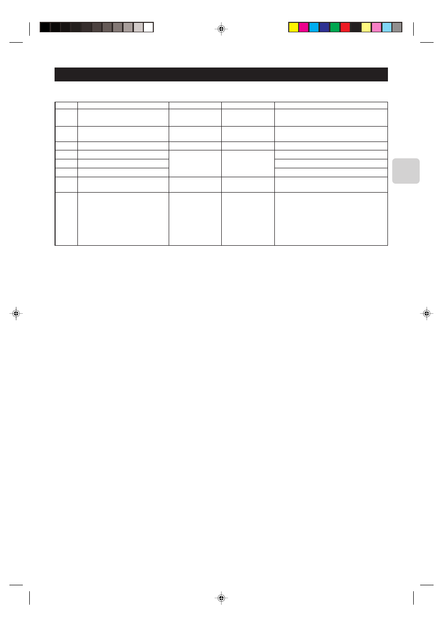
5. Dip Switch Details
■ SW500 - Input/Output Mode Settings
SW No.
No. 1
No. 2
No. 3
No. 4
No. 5
No. 6
No. 7
No. 8
Functions
Not in use
HA terminal (CN504) input switch
HA terminal (CN504) output switch
Remote control (CN591) mode switch 1
Remote control (CN591) mode switch 2
Remote control (CN591) mode switch 3
Relay, extermination output mode switch
Turn on/off with power option
OFF
Set to OFF
Pulse input
Static mode
See the next page
On/Off output
Turn on/off with
power: No
(unit remains off
when the source
power is turned ON)
ON
–
Continuous input
Dynamic mode
See the next page
Error/Ok output
Turn on/off with
power: Yes
(Returns the unit to
the status (on/off) it
was in before the
power was turned
off)
Comments
Be sure to set these to OFF (When set to OFF, the
unit cannot communicate with the air conditioner).
There is a switch between TC1 and 2 input on the
TB571.
When there is a problem while the unit is running,
it will output a relay ON signal.
When the Auto Restart function on the air condi-
tioner itself is set to ON, be sure to set these to
OFF.
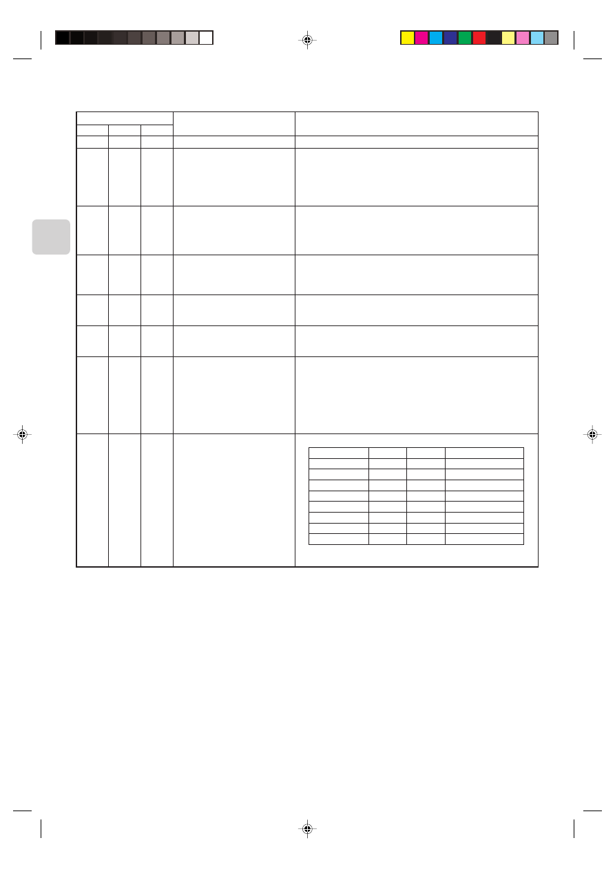
10
Remote control (CN591) mode switch
SW 500
Functions
Do not use the CN591 remote control
On/Off Prohibited/Allowed mode 1
On/Off Prohibited/Allowed mode 2
(level input)
On/Off Prohibited/Allowed mode 3
(pulse input)
Coin timer mode 1 (for a no-voltage
contact point a)
Coin timer mode 2 (for a no-voltage
contact point b)
Cooling-Heating/Temperature settings
mode 1 (3 temperature patterns)
Cooling-Heating/Temperature settings
mode 2 (8 temperature patterns)
Operating Details
–
Manual operations prohibited when CN591 No. 1 and No. 3 are closed, permitted
when open.
Only when No. 1 and No. 3 are closed and manual operations are prohibited.
On when CN591 No. 1 and No. 2 are closed, off when open.
(Cannot be operated from the remote control when manual operations are per-
mitted. Only valid when operated from the CN591.)
On when CN591 No. 1 and No. 2 are closed, off when open.
Manual operations prohibited when No. 1 and No. 3 are closed, permitted when
open.
(Cannot be operated from the remote control when manual operations are per-
mitted. Only valid when operated from the CN591.)
On when CN591 No. 1 and No. 2 are closed, off when No. 1 and No. 3 are closed.
Manual operations prohibited when No. 1 and No. 4 are closed, and permitted
when No. 1 and No. 5 are closed.
(Same as when they are open.)
Permitted and on when CN591 No. 1 and No. 2 are closed, manual operations
prohibited and off when open.
(When permitted, the unit can be operated from the remote control.)
Manual operations prohibited and off when CN591 No. 1 and No. 2 are closed,
permitted and on when open.
(When permitted, the unit can be operated from the remote control.)
On when CN591 No. 1 and No. 2 are closed, off when open.
When No. 1 and No. 3 are closed
20 °C
When No. 1 and No. 4 are closed
24 °C
When No. 1 and No. 5 are closed
28 °C
(When multiple switches No. 3, 4, and 5 are closed, the highest temperature will
be selected.)
Heat when No. 1 and No. 6 are closed, cool when open.
(Remote control operations are valid as always.)
On when CN591 No. 1 and No. 2 are closed, off when open.
No. 1 and No. 3
No. 4
No. 5
Temperature settings
Open
Open
Open
16 °C
Closed
Open
Open
18 °C
Open
Closed
Open
20 °C
Closed
Closed
Open
22 °C
Open
Open
Closed
24 °C
Closed
Open
Closed
26 °C
Open
Closed
Closed
28 °C
Closed
Closed
Closed
30 °C
Heat when No. 1 and No. 6 are closed, cool when open.
(Remote control operations are valid as always.)
No. 5
OFF
OFF
ON
ON
OFF
OFF
ON
ON
No. 6
OFF
ON
OFF
ON
OFF
ON
OFF
ON
No. 4
OFF
OFF
OFF
OFF
ON
ON
ON
ON
11
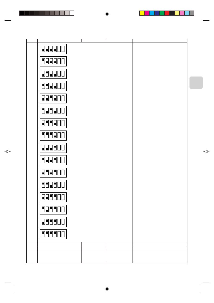
■ SW501: Settings to accommodate MA remote controller and settings to accommodate outdoor units
SW No.
No. 1
No. 2
No. 3
No. 4
Functions
OFF
ON
Comments
Only specify these settings when connecting an
MA remote controller.
Functions
Room temperature detector
MA remote controllers are directly con-
nected to indoor units within the same
group.
ON
1
2
3
4
5
6
ON
1
2
3
4
5
6
ON
1
2
3
4
5
6
ON
1
2
3
4
5
6
ON
1
2
3
4
5
6
ON
1
2
3
4
5
6
ON
1
2
3
4
5
6
ON
1
2
3
4
5
6
ON
1
2
3
4
5
6
ON
1
2
3
4
5
6
ON
1
2
3
4
5
6
ON
1
2
3
4
5
6
ON
1
2
3
4
5
6
ON
1
2
3
4
5
6
ON
1
2
3
4
5
6
ON
1
2
3
4
5
6
Refrigerant address 0
Refrigerant address 1
Refrigerant address 2
Refrigerant address 3
Refrigerant address 4
Refrigerant address 5
Refrigerant address 6
Refrigerant address 7
Refrigerant address 8
Refrigerant address 9
Refrigerant address 10
Refrigerant address 11
Refrigerant address 12
Refrigerant address 13
Refrigerant address 14
Refrigerant address 15
OFF
Indoor unit
Not mixed
ON
Remote control
Mixed
Comments
This should normally be set to OFF.
SW No.
No. 5
No. 6
12
■ SW502 : Air Conditioner Function Settings
(Set this switch based on the functions of the RAC connected to this device.)
SW No.
No. 1
No. 2
No. 3
No. 4
No. 5
No. 6
No. 7
No. 8
Functions
Availability of a heating mode
Not in use
Not in use
Not in use
Not in use
Not in use
Not in use
Availability of a fan (Cooling model only)
OFF
Combined cooler and
heater
–
–
–
–
–
–
Has a fan or mode
OFF
ON
Cooling unit only
–
–
–
–
–
–
No fan or mode ON
Comments
Permanently set to ON.
Permanently set to ON.
Permanently set to ON.
Permanently set to OFF.
Permanently set to OFF.
Permanently set to OFF.
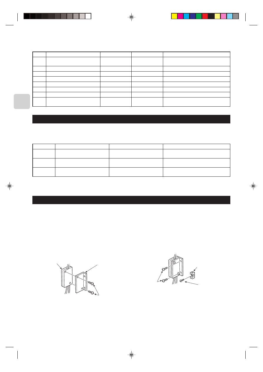
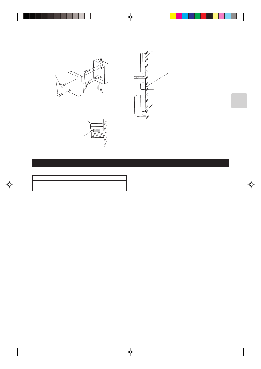
7. Mounting the Remote Control Interface Unit
When mounting the interface to the back-side dent of MFZ-KA model, be sure to apply insulation material to prevent condensa-
tion from forming.
The Remote Control Interface unit should be placed in a location where the connecting cable from the interface can reach an
indoor unit.
The device will not function properly if the connecting cable is extended so the connecting cable should not be extended.
Mount the interface unit securely to a pillar or wall using 2 or more screws.
Mounting screws 3
■ When Using Wall Mounting Brackets 2
1
Attach the wall mounting brackets 2 to the interface unit
1 using 2 mounting screws 3.
Mounting screws C
Interface unit 1
Wall mounting
brackets 2
Mounting
screws 3
Cord clamp for
wiring B
2
Mount the unit to a pillar or wall using 2 mounting screws 3.
6. Test Run (Check Operations)
■ Interface status monitor
You can check the status of the interface by the LED lamp on the interface unit board.
LED lamp no.
LED521
LED522
LED523
Lamp off
DC 12 V is not being supplied from the
air conditioner.
Device is not communicating properly
with the air conditioner.
Device is not communicating properly
with the MA remote controller.
Lamp on
DC 12 V is being supplied from the air
conditioner.
–
–
Blinking
–
Blinking at approx. 1 second intervals: Device is
communicating normally with the air conditioner.
Blinking at approx. 8 second intervals: Device is com-
municating normally with the MA remote controller.
* Use the table above to check the device operations.
13
■ When Mounting Directly to a Wall
Mount the interface unit 1 case to the wall using the mounting
screws 3.
* When mounting the interface unit 1 using a cushioning
material 4, be sure to mount it in a location where it will not
fall.
Interface case
mounting screws D
Mounting
screws 3
Cushioning material 4
Interface unit 1
When mounting the interface unit 1 inside a ceiling
or wall, install an access door to facilitate mainte-
nance.
When the interface unit 1 is mounted
above an indoor RAC unit, it should be
positioned 40 mm or more away from the
unit to ensure that ceiling grills can be
removed.
40 mm or more
Attach the interface unit 1 connecting cable here.
Store extra connecting cable in the ductwork space
behind the indoor RAC unit.
* If there is any slack in the connecting cable, use a
fastener A to keep it in place.
8. Specifications
Input voltage
Power consumption
Input current
12 V
0.6 W
0.05 A

This product is designed and intended for use in the residential,
commercial and light-industrial environment.
The product at hand is based on
the following EU regulations:
• Low Voltage Directive 73/23/EEC
• Electromagnetic Compatibility Directive 89/
336/EEC
HEAD OFFICE: MITSUBISHI DENKI BLDG., 2-2-3, MARUNOUCHI, CHIYODA-KU, TOKYO 100-8310, JAPAN
Printed in Japan
SG79Y415H01
Wyszukiwarka
Podobne podstrony:
IM MAC 399IF E SG79Y416H05 Sep 2009
Powiedz im, Fan Fiction, Dir en Gray
IM PAC YG66DCA WT04977X01 EN 2007
IM PAC YG63MCA WT04975X01 EN 2007
IM PAC YG60MCA WT04973X01 EN 2007
IM MAC 821SC E SG79Y547H02 2007
IM MXZ 4A80VA SG79Y463H01
IM MS MSH MSC GA20 25 35VB SG79Y370H01 EN
IM MSZ GA22 35 MUZ 25 35VA SG79Y421H01 GB Nov 2006
IM MUZ MSZ GB50VA SG79Y676H01 EN 2006
IM MSZ GA50 71VA SG79Y434H01 GB 07 2005
IM MS GA MCT SG79Y368H01 En
mac wyzn
Budzik Versa wielkość karty kredytowej instrukcja EN
60 Rolle der Landeskunde im FSU
G2 4 PW EN wn Rys 01
Manual Acer TravelMate 2430 US EN
IM 5 dyfuzja wyklad 03
więcej podobnych podstron