Errata: Airplane Design Part I, Year of Print: 1985, 1989
1
DESIGN, ANALYSIS AND RESEARCH CORPORATION
ERRATA: AIRPLANE DESIGN PART I
Copyright
1985-89 by Dr. Jan Roskam
Year of Print, 1985, 1989
(Revised June 11, 1997)
page 51,
Eqn. (2.9)
units for c
P
= (lbs/hr)/hp
line 6 from bottom
replace 1,000 nm with 1,000 sm
page 52, line 3
1000 is standard miles
page 61, Table 2.19
Take-off and Landing: groundrun of less than 2,400 ft.
page 64, line 3 and 5
W is the take-off weight: W
TO
page 69, Eqn. (2.23)
D
W
W
W
PL
CREW
p
=
+
+
1
6
exp
Where
W
pexp
is the weight of the expended payload.
(i.e., Missles, bombs, etc.)
page 95, line 14 from bottom remove “range of”
page 98, line 8 from bottom replace C
C
LTO
L
TO
max
max
by
page 106, line 2
replace four factors: with five factors:
page 115, Eqn. (3.18)
V
V
A
s
PA
=
1 1
.
page 132, 4th line
delete “an”
page 150, Eqn. (3.32)
RC
RC
h h
h
abs
=
−
0
1
/
1
6
page 152, Eqn. (3.38)
sin = T
W
P
P
dl
dl
γ
−
−
+
−
−
2
2
1
2
1
P +
L
D
T
W
dl

2
Errata: Airplane Design Part I, Year of Print: 1985, 1989
page 186, Section 3.7.4.2
line 3
...groundrun as < 2,400 ft.
line 7
SL = 1.9 x 2,400 =
= 4,500 ft.
From Figure 3.16
SL = 4,500/0.6 = 7,500 ft.
From Figure 3.17 this yields: VA2 = 25,000 kts2.
V
kts
A
=
=
21 200 1 3 1 2
158
2 1 2
,
. / .
/
0
5
>
C
should be
V
kts
A
=
=
25 000
158
1 2
,
/
:
?
Errata: Airplane Design Part II, Year of Print: 1985, 1989
1
DESIGN, ANALYSIS AND RESEARCH CORPORATION
ERRATA: AIRPLANE DESIGN PART II
Copyright
1985-89 by Dr. Jan Roskam
Year of Print, 1985, 1989
(Revised June 11, 1997)
page 102, Step 3.1, 2
nd
line
...falls into one of the eight catagories...
page 158, Step 6.10
Eqn. (6.1) should be Eqn. (6.2)
page 170,
Eqn (7.8) and (7.11-18)
Cl should be cl
pages 176 to 185
The example problems of Section 7.2 are incorrect. The K
Λ
factor
was multiplied instead of divided to yield the C
lmax
values for Step
7.4 of 7.2.1, 7.2.2, and 7.2.3. Each example will be addressed
below.
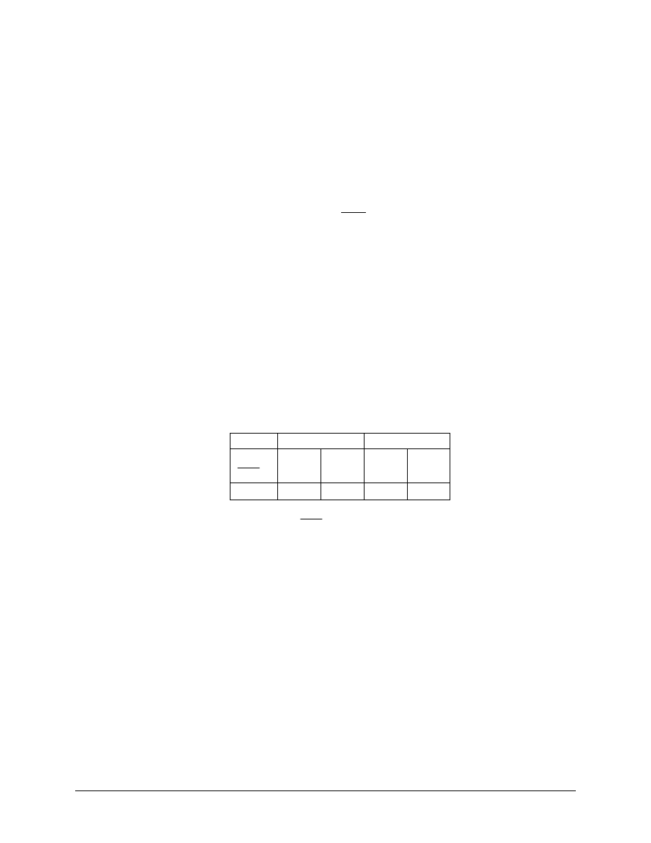
Section 7.2.1 Twin Engine Propeller Driven Airplane
The results of step 7.4 should be:
Take-off flaps
Landing flaps
S
S
wf
0.3
0.6
0.3
0.6
∆
C
lmax
0.58
0.29
2.32
1.16
Z
fh
should be
Z
c
fh
.
For Step 7.5, the referenced equations and figures are wrong:
Eqn. (7.15) should be Eqn. (7.16).
Eqn. (7.14) should be Eqn. (7.15).
Eqn. (7.13) should be Eqn. (7.14).
Figure 7.7 should be Figure 7.8.
Figure 7.3b should be Figure 7.4.
Eqn. (7.10) should be Eqn. (7.11).
2
Errata: Airplane Design Part II, Year of Print: 1985, 1989
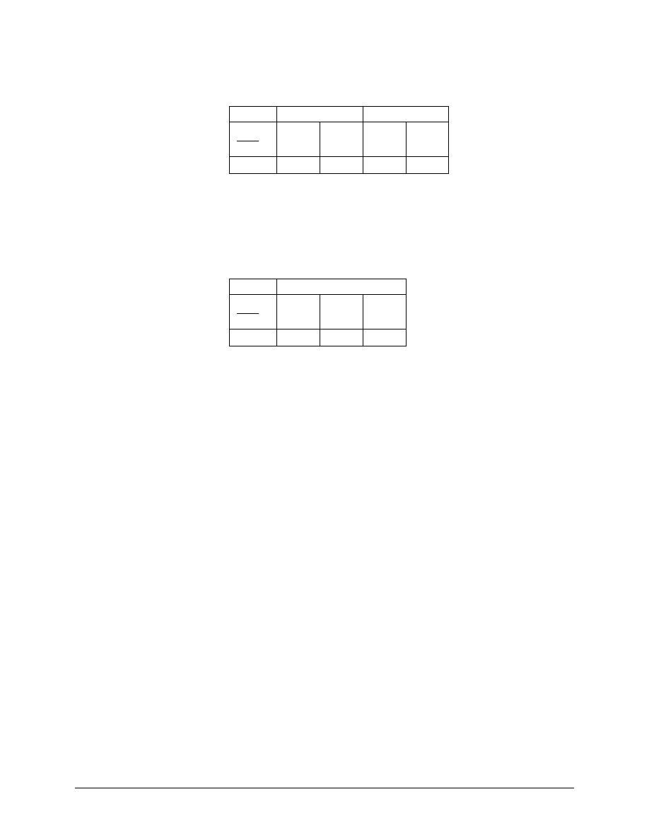
Section 7.2.2 Jet Transport
The results of step 7.4 should be:
Take-off flaps
Landing flaps
S
S
wf
0.6
0.8
0.6
0.8
∆
C
lmax
3.00
2.24
3.84
2.88
For Step 7.5, the referenced equations and figures are wrong:
Eqn. (7.10) should be Eqn. (7.11)
Figure 7.3b should be Figure 7.4
Section 7.2.3 Fighter
The results of Step 7.4 should be:
Take-off flaps
S
S
wf
0.4
0.8
1.0
∆
C
lmax
4.00
2.000
1.60
These corrections will affect the results of each sample problem. It
is left to the reader to complete the sample problems using the
correct results of Step 7.4. The summary and referenced drawings
of Step 7.6 may change due to these corrections.
pages 178, 181, and 184
Under Step 7.4, K
∆
should be K
Λ
page 267
Eqn (11.13)
N
N
D
t
crit
=
0 75
.
should be N
N
D
t
crit
=
0 25
.
Eqn (11.14)
N
N
D
t
crit
=
0 25
.
should be N
N
D
t
crit
=
0 10
.

Errata: Airplane Design Part III, Year of Print: 1986, 1989
1
DESIGN, ANALYSIS AND RESEARCH CORPORATION
ERRATA: AIRPLANE DESIGN PART III
Copyright
1986-89 by Dr. Jan Roskam
Year of Print, 1986, 1989
(Revised March 15, 1999)
page 15, Table 2.3
Switch values for
β
1
and
β
2
page 194, 8th line from top
replace “stability” with “Stability”.

Errata: Airplane Design Part IV, Year of Print: 1986, 1989
1
DESIGN, ANALYSIS AND RESEARCH CORPORATION
ERRATA: AIRPLANE DESIGN PART IV
Copyright
1986-89 by Dr. Jan Roskam
Year of Print, 1986, 1989
(Revised December 14, 1999)
page 54, Table 2.18
For fighters and trainers, the details are in Figure 2.26, not Figure
2.25.
page 380, 7th line from top
replace “is” with “are”
Errata: Airplane Design Part V, Year of Print: 1985, 1989
1
DESIGN, ANALYSIS AND RESEARCH CORPORATION
ERRATA: AIRPLANE DESIGN PART V
Copyright
1985-89 by Dr. Jan Roskam
Year of Print: 1985, 1989
(Revised December 14, 1999)
page 34, Eqn (4.13)
n
GW
pos
lim
.
,
/
,
≥
+
+
2 1 24 000
10 000
0
5
page 43, 12
th
line from top VA should be 217 kts.
page 45, 8
th
line
Change Selene to Eris
page 61, under Step 6
nult = 7.33 should read nlim = 7.33
page 71
Eqn (5.12)
57.5 should be 174.04
Eqn (5.13)
15.6 should be 639.95
Replace exponent 1.249 with 0.1249
page 72
6
th
line
replace ‘ib’ with ‘in’
13
th
line replace
1 4
/
V 1/ 4V
by
Λ
page 72 - 74
All comments about the canard weight should reference 5.2.1.1.
page 74
Eqn (5.19)
Replace 1 2
/
H 1/ 2H
by
Λ
Eqn (5.20)
(
)
(
)
0.2
2
3.81
1000 cos
0.287
v
v v
v
D
c v
W
K S
S
V
=
Λ
−
Replace 1 2
/
V 1/ 2V
by
Λ
page 75, Eqn (5.23)
W
W
P
l
f
TO
f n
=
−
0 04682
0
0 374
0 590
.
.692
max
.
.
1 6 1 6 3 8
where
Pmax is the maximum fuselage perimeter expressed in feet.
page 76
Eqn (5.24)
N
pax
is the number of passengers including the pilot.
Eqn (5.26)
Replace 2 x 10.43 by 10.43
page 77, Eqn (5.27)
h
l = distance from wing root c/4 to horizontal tail root c/4 in ft
page 78, Eqn (5.29)
W
K W
n
n
TO
=
should be W
K P
n
n
TO
=
2
Errata: Airplane Design Part V, Year of Print: 1985, 1989
page 79
2
nd
line
Eliminate and replace by “P
TO
= Take-off power in HP”
Eqn (5.32)
(
) ( )
4
/
1
e
4
/
5
TO
n
N
P
045
.
0
W
−
=
page 81
Eqn (5.38)
( )
(
)
( )
( )
(
)
( )
0.183
0.417
0.950
.
0.788
0.749
.
0.013
0.362
6.2
0.0013
0.007157
g
TO
L
ult l
sm
TO
L
ult l
sn
W
W
W
n
l
W
W
n
l
=
+
+
+
+
+
7
th
line from bottom
Replace N
ult.l
by n
ult.l
4
th
line from bottom
Replace 62.61 by 62.21
page 85
Section 6.1.2, 9
th
line
Should read: Equations (6.4) and (6.6) may also be used...
page 87, Eqn (6.8)
( ) (
)
7
.
0
TO
3
.
0
e
p
ai
P
N
1.03
W
W
=
+
page 90, Eqn (6.14)
Method assumes that the number of engines equals the number of
propellers
page 92, Eqn (6.23)
W
W
K
fs
f
fsp
=
1 6
0 727
.
.
See the associated insert for the comparison of Torenbeek and GD
methods.
page 93,
Add an increment of 5 to all equation numbers throughout Chapter
6 (i.e., Eqn. (6.22) becomes Eqn. (6.27)).
page 95, Eqn (6.34b)
( ) (
)
8
.
0
TO
2
.
0
e
b
apsi
P
N
0.4K
W
=
page 98,
Add an increment of 1 to all equation numbers throughout Chapter
7.
page 99, Eqn (7.4)
W
W
fc
TO
=
0 33
2 3
.
/
1 6
page 108,
Eqn (7.44) Remove the ( before N
pax
in the cabin windows
weight component.
page 109, Eqn (7.46)
Kst = 0 for no ejection seat
page 111,
3
rd
line of Section 7.12 Should
read:
Part IV, Chapter 3.
Errata: Airplane Design Part VI, Year of Print: 1987, 1990
1
DESIGN, ANALYSIS AND RESEARCH CORPORATION
ERRATA: AIRPLANE DESIGN PART VI
Copyright
1987-90 by Dr. Jan Roskam
Year of Print, 1987, 1990
(Revised December 14, 1999)
page xx
x
x
c
ac
h
ac
h
=
/
page 27, Eqn (4.9)
CL
w
CL CL
c
Sc
S
CL
h
Sh
S
=
−
−
page 46, Eqn (4.33)
3
2
2
b
plf
fus
fus
D
d
L
c
fus
S
S
C
c
S
S
α
η
α
=
+
page 47, Figure 4.20
sin
c
M
M
α
=
page 49
Eqn (4.39)
C
S
S
DL fus
b fus
=
α
2
4 9
/
Eqn. (4.41)
C
C
S
S
C
C
C
C
S
S
Do fus
f fus
wet fus
fus
DN
DA
DA NC
Db fus
fus
=
+
+
+
+
2
0 5
page 52, Eqn (4.43)
3
2
2
b
plf
fus
fus
D
d
L
c
fus
S
S
C
F
c
S
S
α
α
=
+
page 70, 9
th
line
Should read
“... of 4.2.2.1 but with the appropriate...”
page 73
Eqn. (4.60)
Add:
ε
n
> 0
for upwash and
ε
n
<
0
for downwash
Last line
Should read: Chapter 8.
page 77, Eqn. (4.63)
∆
c
i
l
n
2
0 056
= +
.
1 6
with in expressed in degrees
page 86
3
rd
line Should
read:
...
from Eqn. (4.6)
Eqn. (4.74)
‘Chapter 9’ should be ‘Chapter 8’
page 105, Eqn (4.84)
( )
( )
4
0
4
4
0
4
cos
cos
ef
h
D
D
c
trim
p
h
prof
c
h
h
cf
c
D
c
p
c
c
c
c
S
S
C
C
S
S
S
S
C
S
S
Λ
=
Λ
=
∆
= ∆
Λ
+ ∆
Λ
2
Errata: Airplane Design Part VI, Year of Print: 1987, 1990
page 142
The reference to Chapter 6 in Part IV should be Chapter 7
page 171, Eqn. (6.25)
Replace
P
JDV
•
with
P
D
•
Where
P
D
•
follows from Eqn. (6.19)
page 177, 22
nd
line
Section on supersonic jet inlets should be Section 6.2.3.4
page 181, Eqn. (6.44)
F
A
A
inl
inl
inl
m
c
= +
−
−
%
&KK
'KK
(
)KK
*KK
1 1 75
1
1
1
.
µ
µ
page 229, Eqn. (8.7)
( )
(
)
{
}
( )
(
)
∆
c
c
c
c
c
c
c
c
l
l f
f
l
f
f
=
+
+
′
η
δ
η
δ
δ
δ
1
1
1
1
2
2
2
/
/
page 233, Eqn. (8.10)
Φ
TEUPPER
y
y
c
=
−
arctan{
}
10
90
100
page 245, Eqn. (8.20)
α
α
w
w
i
= +
page 268, Eqn. (8.32) Should
be
C
C
C
S
S
C
S
S
Lo
Lowf
L
h
h
h
oh
o Lh
L
c
c
c
oc
o Lc
=
+
−
−
+
−
α
α
η
ε
α
η
ε
α
1 6
1 6
where:
α
o Lh
and
α
o Lc
can be found using the method of Section
8.1.3.1.
page 269, Eqn (8.37)
For jet airplanes, the horizontal tail dynamic pressure should be
calculated from:
2
2.42
cos
2
0.30
1
h
hwake
Dow
wake
h
wake
C
z
x
c
z
π
η
∆
+
= −
where:
Dow
C
is the wing zero-lift drag coefficient as found from 4.2.1.1.
(
)
sin
h
h
w
h
wake
z
a
i
α
ε
γ
=
− − +
(
)
cos
h
h
w
h
wake
x
a
i
α
ε
γ
=
− − +
0.15
0.68
h
wake
wake
Dow
x
C
c
z
c
+
∆
=
Errata: Airplane Design Part VI, Year of Print: 1987, 1990
3
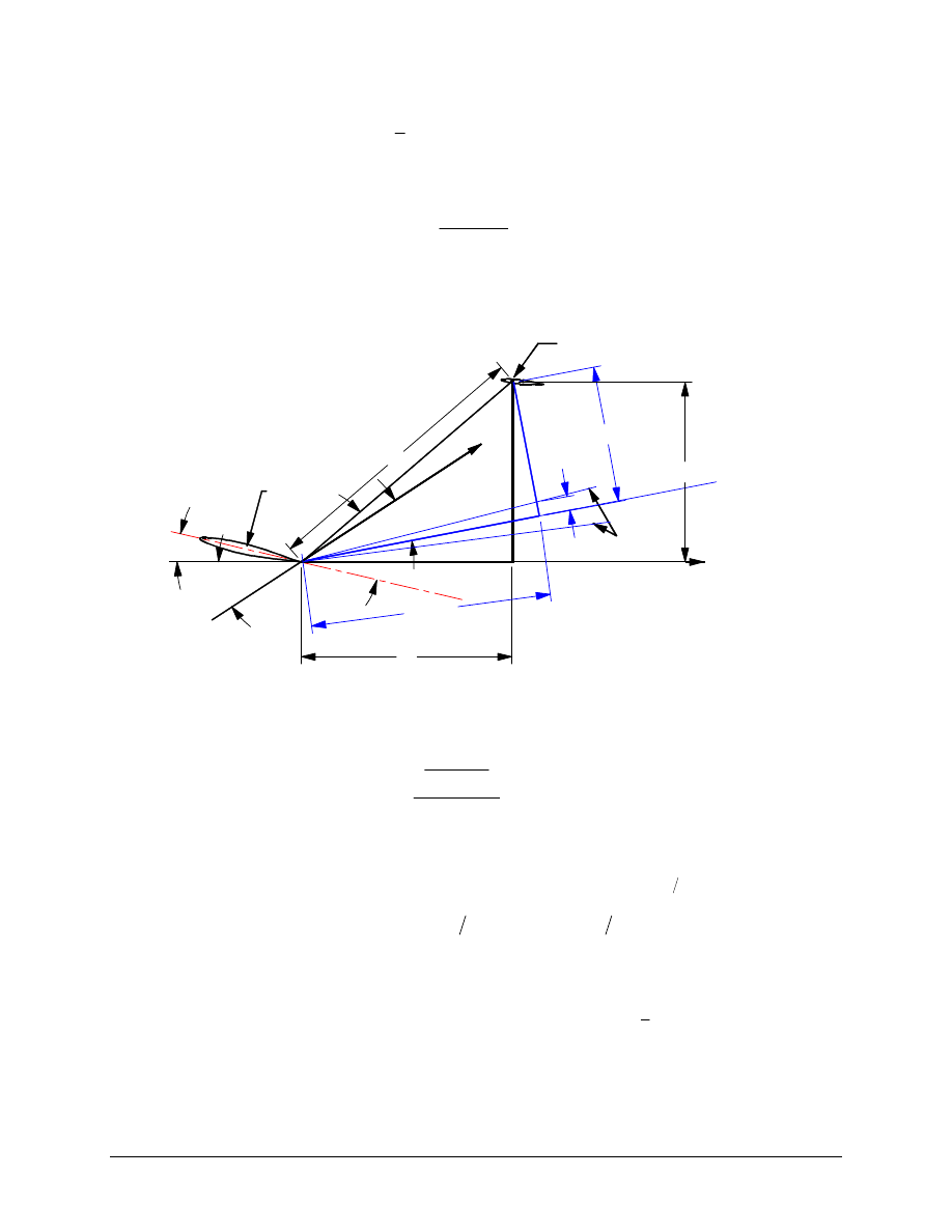
page 269, Eqn (8.37) (Cont.)
with:
a
and
h
γ
shown in Figure 8.63;
c as the wing mean geometric chord;
α
as the airplane angle of attack;
w
i
as the wing incidence angle; and
1.62
Lw
cl
C
A
ε
π
=
page 270, Figure 8.63
Should be
W a k e L im its
H o riz o n ta l Ta il
A e ro d y n a m ic C e n te r
C e n te rlin e o f
W a k e a n d
Vo r te x S h e e t
P a ra lle l to th e
B o d y A x is
(R e fe re n c e A x is )
F re e S tr e a m
W in g R o o t C h o rd
l
a
w
i
α
TE
Z
hwake
Z
wake
Z
∆
h
ε
hwake
X
h
γ
page 275, Eqn. (8.50)
Parenthesis after
ε
0h
should be moved to after d
ε
/d
α
.
page 279, Fig. (8.70)
Units for
∆ε
∆
f
f
L
w
Ab
b
C
should be degrees
page 280, Eqn. (8.54)
∆
∆
∆
∆
∆
C
K
C
C
S
S
C
S
S C
Lmax
cw
Lmaxw
L
w
w c
c
Lmaxc
h
L
h
f
=
−
+
+
−
α
δ
α
α
ε
1 6
1 6
3 8
page 305, Eqn (8.73)
The bar over the 2 should be over the c.
page 311, Eqn (8.74)
The first term on the r.h.s. should read: x
C
ref
Lw
−
0 25
.
3
8
∆
where:
∆
C
Lw
is the wing lift increment due to flaps.
page 320, Eqn (8.78)
Replace ‘i
w
’ with ‘
−
i
w
’.
4
Errata: Airplane Design Part VI, Year of Print: 1987, 1990
page 323, 1
st
line
Should read
airplane zero angle of attack. . .
page 333, Eqn. (8.97)
ε ε
α ε
α
=
+
oh
h
d
d
page 333, Eqn. (8.97)
ε ε
α ε
α
=
+
oc
c
d
d
page 340, Eqn. (8.107)
( )
K
SHP
W
S
D
Ti
AVi
Pi
=
550
2
3 2
2
ρ
page 342, Eqn. (8.108)
dC
dC
dC
d
d
d
l
D
Sc C
m
L N
N
Pi
Pi
Pi
Pi
L
w
i
n
1
6
1
6 4
94 91 64 9
=
!
"
$
##
#
=
∑
α
ε
α
α
0 79
2
1
.
page 374, Eqn. (10.8)
C
C
T
X
D
1
1
=
page 375, Last Line
∂
∂
C
C
D
m
should be
∂
∂
C
M
D
.
page 377
Eqn. (10.12)
C
C
X
M M
mu
L
aca
=
−
1
∂
∂
/
4
9
Eqn. (10.13)
C
qS
P
u
C
Txu
reqd
Tx
=
∂
∂ −
1
3
1
0 53
8
Eqn. (10.15)
C
M
qS
T
M
C
TXu
reqd
TX
=
−
(
/
)(
/
)
1
1
3
∂
∂
page 382,
Eqn (10.24)
Add a ‘)’ to the end of Equation 10.24
2
nd
line below Eqn (10.24)
Equation ‘(10.23)’ should be equation ‘(10.22)’.
page 390, Fig. (10.16)
h
z should be ‘the vertical distance between the horizontal tail
aerodynamic center to the fuselage center line’.
page 397,
6
th
line from bottom
Replace C
C
y
y
v
β
β
by
page 398, Eqn (10.44)
C
i
n
Sum
i
dC
d
D
l
Sb
nT
N
pi
Pi
pi
β
α
= −
=
=
%&'
()*
!
"
$#
1
0 79
2
1
6 0 54 9 4 9
.
page 401~415, Fig.30~33
f
p
f
p
v
l
z
z
α
α
cos
cos
−
=
Errata: Airplane Design Part VI, Year of Print: 1987, 1990
5
page 417, Eqn (10.50)
C
C
z
l
z
b
z
b
C
y
p
y
v
v
v
v
lp
C
L
=
−
−
+
−
=
=
2
3
1
4
0
0
β
α
α
cos
sin
sin
sin
Γ
Γ
Γ
4 9
where: z - is the vertical distance between the cg and the wing
root quarter-chord point.
C
k
C
k
lp
C
L
lp
C
L
4 9
Γ=
=
=
=
0
0
0
β
β
page 418, Figure 10.35
Replace
β
C
k
lp
with
β
C
k
lp
C
L
=
0
page 419, Eqn. (10.55)
C
C
z
b
z
b
lp
lp
w
w
4 9
4 9
Γ
Γ
Γ
Γ
=
= −
+
0
2
1
4
12
sin
sin
page 421, Eqn.(10.62)
C
C
C
C
C
C
n pw
n p
L C
M
Lw
n p
t
t
n p
f
f
f
f
L
=
%&K
'K
()K
*K
+
+
!
"$#
=
4
9
4
9
0
ε ε
α
δ
α
δ
δ
δ
∆
page 422, Eqn. (10.66)
α
δ
δ
α
f
l
l
f
c
c
= ∆
/
4 9
page 424, Eqn. (10.71)
( )
0
0.5
2
w
L
L
qw
w
M
x
C
C
c
α
=
=
+
page 435, Eqn. (10.89)
C
C
Ae
C
S
S
Dih
L
L
h
h
h
=
2
π
η
α
page 439,
Eqn. (10.97)
C
C
Ae
C
S
S
Dic
L
L
c
c
c
=
2
π
η
α
Eqn. (10.100)
C
C
V
mic
L
c
c c
=
α
η
page 440, Eqn (10.102)
Replace
l
h
c
α
with
l
c
c
α
page 446, Eqn (10.110)
c
c
c
c
k
l
l
l
theory
l
theory
δ
δ
δ
δ
=
4 9 4 9
'
where k' is found from Figure 8.13
6
Errata: Airplane Design Part VI, Year of Print: 1987, 1990
page 447,
Eqns. (10.111) & (10.113)
It is assumed that:
C
C
l
left
l
right
δ
δ
=
page 461, Eqn. (10.123) Should
read:
C
K C
S
S
c
c
c
k
c
y
r
L
v
v
l
l
theory
l
theory
l
v
CL
cl
δ
δ
α
δ
δ
δ
α
δ
δ
α
α
=
%
&K
'K
(
)K
*K
%
&K
'K
(
)K
*K
4 9
4 9
2 7
2 7
'
Eqn (10.123) is correct for a single vertical tail only. For a twin
vertical tail:
C
C
C
K C
S
S
c
c
c
k
c
y
r
y
v wfh
y
veff
b
L
v
v
l
l
theory
l
theory
l
v
CL
cl
δ
β
β
α
δ
δ
δ
α
δ
δ
α
α
=
%
&K
'K
(
)K
*K
%
&K
'K
(
)K
*K
2
0 5
4 9
4 9
2 7
2 7
'
where:
C
C
y
v wfh
y
veff
β
β
0 5
is found from Figure 10.17.
All other parameters are the same.
page 467, Eqn. (10.129)
c
h
theory
α
4 9
is found from Figure 10.63b. The parameter
c
c
l
l
theory
α
α
4 9
in Figure 10.63b is itself found from Figure 10.64a
with the assumption that tan
'
Φ
TE
t
c
2
=
.
page 470,
1
st
line
(10.126) should be (10.128).
Eqn. (10.130)
c
c
l
l
theory
α
α
4 9
is obtained from Figure 10.64a with the assumption
that tan
'
Φ
TE
t
c
2
=
.
page 484, Eqn (10.145)
Replace ‘
α
δ
’ with ‘–
α
δ
’.
page 521,
(Pratt and Whitney handbook errors)
Pressure (psia) for 200,000 ft should be 0.002655 psia
Pressure (psia) for 200,131 ft should be 0.002641 psia
Pressure
Ratio,
δ
, for 154,199 ft should be 0.001095
Errata: Airplane Design Part VII, Year of Print: 1988, 1991
1
DESIGN, ANALYSIS AND RESEARCH CORPORATION
ERRATA: AIRPLANE DESIGN PART VII
Copyright
1988-91 by Dr. Jan Roskam
Year of Print: 1988, 1991
(Revised December 14, 1999)
page 11,
last sentence of 3
rd
para.
Typical numerical values for gearing ratios are given in Table 4.1
of Part IV, not Part VI.
page 39, Figure 2.5
z
T
should be negative as shown
page 44, Eqn. (2.39) Should
read:
S
z T
z D W x
x
z
L
x
x
z
C
q
Sc
I
q
x
x
z
C
h
T
D
mg
cg
g mg
wf
mg
acwf
g mg
macwf
g
rot
yymg
rot
mg
ach
g mg
Lh
=
−
+
+
−
+
−
−
+
−
+
−
+
µ
µ
µ
3
8
4
9
4
9
max
Θ
page 49, Eqn. (2.54)
The 4
th
term on the left hand side should read:
‘+ Y
x
x
ng
ng
cg
+
3
8
- ...’
page 50, Eqn. (2.57)
The 4
th
term on the left hand side should read:
0 025
.
Ψ
Ψ
A
steer
ng
ng
cg
P
x
x
+
+
1
6 3
8
page 98, 1
st
sentence
Should read, “Civil: FAR 23.201, 23.203, 23.205, ...”
page 152, Eqn. (5.59)
T
C qS
W
W g U Q
t
L
sin
cos
/
sin
α φ
φ
φ
+
+
−
−
=
1 6
0 5
1 1
0
page 159,
Last sentence of 1st para.
Should read, “See Section 5.3.”
page 161, Eqn. (5.77)
RD = W / S
0 50 53
80 5
J
L
2
2
3
3 1 2
/
/
cos
/
ρ
γ
C
C
D
L
page 164, AS-5263
thrust required for level flight at 1 15
.
V
s
, not 1 15
.
V
s
PA
.
Wyszukiwarka
Podobne podstrony:
CATALOGUE OF PALAEARCTIC COLEOPTERA I LOBL & A SMETANA Vol 1 5 Errata
Algebraic Number Theory (Math 784 instructors notes) (1997) WW
Matrix Theory [jnl article] T Banks (1997) WW
Basic Concepts in Nonlinear Dynamics and Chaos (1997) WW
Advanced Calculus J Weinstein (1997) WW
Functional Analysis [lecture notes] D Arnold (1997) WW
Getting Started with PIC Microcontrollers F Stevens (1997) WW(1)
Introduction to Smooth Manifolds [Errata] J Lee (2000) WW
Vol.IV-1997, Transkrypty sesji channelingowych
Inverse problem Theory A Tarantola (ERRATA) (2005) WW
Eurocode 7 Part 1 1997 2004 Geotechnical Design General Rules UK NA
Math [DOE Fundamentals] Vol 2 (DOE HDBK 1014 2 92) (1992) WW
The Journal of Transpersonal Psychology Vol 29 1 (1997)
Vol 14 Podst wiedza na temat przeg okr 1
obiektywne metody oceny postawy ciała (win 1997 2003)
Konstytucja 2 kwietnia 1997
więcej podobnych podstron