i

ii
FCC Compliance
USER-INSTALLER CAUTION:
YOUR AUTHORITY TO OPERATE THIS FCC VERIFIED
EQUIPMENT COULD BE VOIDED IF YOU MAKE CHANGES OR MODIFICATIONS NOT
EXPRESSLY APPROVED BY THE PARTY RESPONSIBLE FOR COMPLIANCE TO PART 15 OF
THE FCC RULES.
NOTE:
THIS EQUIPMENT HAS BEEN TESTED AND FOUND TO COMPLY WITH THE LIMITS
FOR A CLASS A DIGITAL DEVICE, PURSUANT TO PART 15 OF THE FCC RULES. THESE
LIMITS ARE DESIGNED TO PROVIDE REASONABLE PROTECTION AGAINST HARMFUL
INTERFERENCE WHEN THE EQUIPMENT IS OPERATED IN A COMMERCIAL ENVIRONMENT.
THIS EQUIPMENT GENERATES, USES, AND CAN RADIATE RADIO FREQUENCY ENERGY
AND IF NOT INSTALLED AND USED IN ACCORDANCE WITH THE INSTRUCTION MANUAL,
MAY CAUSE HARMFUL INTERFERENCE TO RADIO COMMUNICATIONS.
OPERATION OF THIS EQUIPMENT IN A RESIDENTIAL AREA IS LIKELY TO CAUSE HARMFUL
INTERFERENCE IN WHICH CASE THE USER WILL BE REQUIRED TO CORRECT THE
INTERFERENCE AT HIS OWN EXPENSE.
THIS CLASS A DIGITAL APPARATUS MEETS ALL REQUIREMENTS OF THE CANADIAN
INTERFERENCE-CAUSING EQUIPMENT REGULATIONS.
iii
Warnings and Cautions
WARINGS
TO PREVENT THE RISK OF FIRE OR ELECTRIC SHOCK. DO NOT EXPOSE THIS PRODUCT
TO RAIN OR MISTURE.
DO NOT INSERT ANY METALLIC OBJECT THROUGJ VENTILATION GRILLS.
CAUTION
CAUTION
RISK OF ELECTRIC SHOCK
DO NOT OPEN
CAUTION: TO REDUCE THE RISK OF ELECTRIC SHOCK.
DO NOT REMOVE COVER (OR BACK).
NO USER-SERVICEABLE PARTS INSIDE.
REFER SERVICING TO QUALIFIED SERVICE PERSONNEL.
Explanation of Graphical Symbols
The lightning flash with arrowhead symbol, within an equilateral triangle, is
intended to alert the user to the presence of insinuated “dangerous voltage” within
the product’s enclosure that may be of sufficient magnitude to constitute a risk of
electric shock to persons.
The exclamation point within an equilateral triangle is intended to alert the user to
the presence of important operating and maintenance (servicing) instruction in the
literature accompanying the product.
USERS OF THE SYSTEM ARE RESPONSIBLE FOR CHECKING AND COMPLYING WITH ALL
FEDERAL, STATE, AND LOCAL LAWS AND STATUTES CONCERNING THE MONITORING
AND RECORDING OF VIDEO AND AUDIO SIGNALS. ULTRAK SHALL NOT BE HELD
RESPONSIBLE FOR THE USE OF THIS SYSTEM IN VIOLATION OF CURRENT LAWS AND
STATUTES.

iv
TABLE OF CONTENTS
CHAPTER 1 INTRODUCTION ------------------------------------------------------------ 1
CHAPTER 2 HARDWARE OVERVIEW ------------------------------------------------- 2
CHAPTER 3 SETUP PROCEDURES --------------------------------------------------- 6
1. MAIN MENU SETUP ----------------------------------------------------------- 6
2. SYSTEM SETUP ---------------------------------------------------------------- 6
3. CAMERA SETUP ---------------------------------------------------------------- 7
4. MOTION SETUP ----------------------------------------------------------------- 8
5. RECORD SETUP ---------------------------------------------------------------- 9
6. ALARM SETUP ------------------------------------------------------------------- 10
7. EVENT LIST ----------------------------------------------------------------------- 11
8. HDD MANAGEMENT ----------------------------------------------------------- 12
9. LOAD DEFAULT ------------------------------------------------------------------ 13
10. EXIT --------------------------------------------------------------------------------- 13
CHARPTER 4 OPERATION PROCEDURES ------------------------------------------ 14
1. GETTING STARTED WITH YOUR MACHINE --------------------------- 14
2. RECORDING ---------------------------------------------------------------------- 14
3. PLAYBACK ------------------------------------------------------------------------- 14
4. AUDIO RECORDING AND PLAYBACK ------------------------------------ 15
5. NETWORK FUNCTION --------------------------------------------------------- 15
6. HARD DISK AND CF CARD RECOMMEND ------------------------------ 15
7. BACKUP ---------------------------------------------------------------------------- 16
8. ALARM CONTROL -------------------------------------------------------------- 17
9. EXTERNAL ALARM CONNECTOR ----------------------------------------- 18
10. RS-232/RS-485 CONNECTOR ----------------------------------------------- 18
11. RS-232/RS-485 CONTROL PROTOCOL ---------------------------------- 19
SPECIFICATIONS ----------------------------------------------------------------------------- 20
TIME LAPSE RECORD TIME -------------------------------------------------------------- 22
V1.06 24/Feb/2005
v
MENU SETUP LIST
SYSTEM SETUP
DATE 2004/06/10
TIME 10:10:10
DATE FORMAT Y-M-D
AUTO SWITCH DWELL 02 SEC
SPOT SETUP
DATE AND TIME OSD ENABLE
SYSTEM TYPE NTSC
KEYBOARD LOCK OFF
PASSWORD PROTECT DISABLE
EXIT
SETUP MENU
SYSTEM
CAMERA
MOTION
RECORD
ALARM
EVENT LIST
HDD MANAGEMENT
LOAD DEFAULT
EXIT
CAMERA SETUP
CAMERA CAM 01
DISPLAY ON
RECORD ON
BRIGHTNESS 50
CONTRAST 50
HUE 50
COLOR 50
CAMERA TITLE 01
EXIT
MOTION SETUP
CAMERA CAM 01
MOTION DETECTION ON
BUZZER OFF
SENSITIVITY 070
AREA SETUP
EXIT
RECORD SETUP
NORMAL RECORD FPS 30P
ALARM RECORD FPS 30P
ALARM RECORD DWELL 10 SEC
RECORD QUALITY HIGH
AUDIO RECORD ON
SCHEDULE RECORD OFF
EXIT
ALARM SETUP
BUZZER
BUZZER/ALARM DWELL 05 SEC
VIDEO LOSS ALARM ON
AUDIBLE ALARM ON
EXT.ALARM MODE LOW
ALARM DISPLAY MODE DISABLE
MOTION EVENT OFF
RELAY
EXT.ALARM RELAY ON
VIDEO LOSS RELAY ON
MOTION RELAY ON
EXIT
HDD MANAGEMENT
OVERWRITE MODE OFF
CAPACITY WARNING 20%
HDD FORMAT SETUP
EXIT
DISK CAPACITY LEFT RATIO
A 250GB 100%
B NONE NONE
SPOT SETUP
SPOT SWITCHING:ON
CAM01:02 SEC CAM09:02 SEC
CAM02:02 SEC CAM10:02 SEC
CAM03:02 SEC CAM11:02 SEC
CAM04:02 SEC CAM12:02 SEC
CAM05:02 SEC CAM13:02 SEC
CAM06:02 SEC CAM14:02 SEC
CAM07:02 SEC CAM15:02 SEC
CAM08:02 SEC CAM16:02 SEC
EXIT
HDD FORMAT SETUP
HDD PASSWORD PROTECT ENABLE
HDD PASSWORD 1 1 1 1
FORMAT
EXIT
SCHEDULE RECORD
OOOOOOOOOOOOOOOOOOO
0 3 6 9 12 15 18 21 24
O:FULL REC
A:ALARM REC
X:NO REC

1
CHAPTER 1
INTRODUCTION
9ch & 16ch DVR are 9 (16) cameras input appliance with multiple function which will bring you following
features:
z
Digitize data storage with wavelet compression technology will give you organized video data
management without using mess huge traditional video tape。
z
Device operates in hardware base with no OS (operating system) necessary for more reliability and
stability。
z
All 9 / 16 channels are duplex。
z
Support various type of camera with real-time, live mode display。
z
Multi-speed recording selection on normal recording mode or alarm recording mode, the highest speed
of recording is 60/50 (NTSC/PAL) fields on both mode。
z
All 9 / 16 channels can be setting up for display and recording individually。
z
All 9 / 16 channels can be setting up for motion detection individually and each channel is divided by 48
motion detection areas with 100 levels adjustable sensitivity.
z
Contrast, hue and brightness are adjustable for each camera individually。
z
Support up to 2 hard disks (HDD) from 40GB to 250GB compatible and one of those drives can be set
as removable。
z
When external alarm is triggered , correspond cameras will show up on the monitor with red texts。
z
Selectable recording qualities (best/high/medium/low)。
z
Recording can operate manually or gets activated automatically when alarm is triggered。
z
Schedule recording
z
You can search for a video record by time or by checking event log。
z
Play back mode could not be easier then ever for you to review the video that gets recorded on fast
reverse and fast forward (×2, ×4, ×6, ×8)。
z
Play back mode with pause (field by field) for both forward and backward。
z
Easy operation, setting can be easily modified OSD (on screen display) menu。
z
The video losing will be log up on event list and the operator will receives the warning notification
automatically。
z
Device will overwrites data and notice operator on monitor when the HDD is going full。
z
HDD capacity status can be display on the screen for better storage management。
z
Audio input support up to 1 channel。
z
Network support enhance the ability of truly remote surveillance monitoring (optional)。
z
Support composite video, Y/C video signal output and full screen spot monitor output。
z
Support compact flash (CF) card (network model only) for random backup and VCR for fully backup.
z
Provide key lock function and two sets of password protection。
z
Up to 3000 event lists can be recorded (PWR/REC/EXT/LOS/MOT)。
z
Build-in RS-232 and RS-485 port are ready for sub-control panels add on in the future。
z
System will restore the previous setting and continue camera activity after restart。
z
No need to interrupt the video recording while changes setting.
2
CHAPTER 2
HARDWARE OVERVIEW
22
23
19 20 21
14
18
17
16
15
1
2
4
3
5
6
7
8
9
10 11 12
9
7
8
3
4
5
6
1
2
AUTO
ENTER
SEL
MENU
Digital Video Recorder
Copy
Play
Search
F.Fwd
Field
Fwd
PLAY H.D.D
Stop
Field
Rew
Rew
Rew
Search
POWER
Rec
REC
13
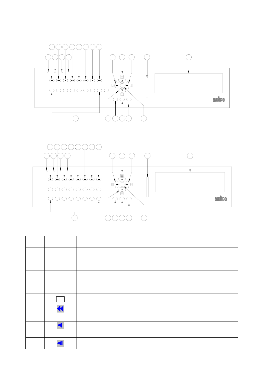
Front Panel of 9-ch DVR
7
ENTER
SEL
AUTO
MENU
18
14
13
20
19
15
16
17
12
11
10
9
8
7
6
5
3
4
2
1
23
22
Digital Video Recorder
Copy
Play
Fwd
Field
Search
F.Fwd
PLAY H.D.D
Search
Rew
Rew
Rew
Field
Stop
POWER
Rec
REC
21
10
9
12
11
14
13
16
15
2
1
6
5
4
3
8
Front Panel of 16-ch DVR
Part Label
Function
1
POWER
Power LED
2
REC
Recording LED
3
PLAY
Play LED
4
H.D.D
H.D.D LED
5 Rec
Press Rec to start recording. Press again to stop.
6
Rew Search
From ×2,×4,×6, to the highest ×8 speed fast rewind mode, speed and rewind
sign will be indicated in top left corner on the screen.
7
Rew
Press the Rew button to play video backward, press the button again to
circulative change from normal speed to 1/2 speed and 1/4 speed
8
Press Field Rew to pause video backward
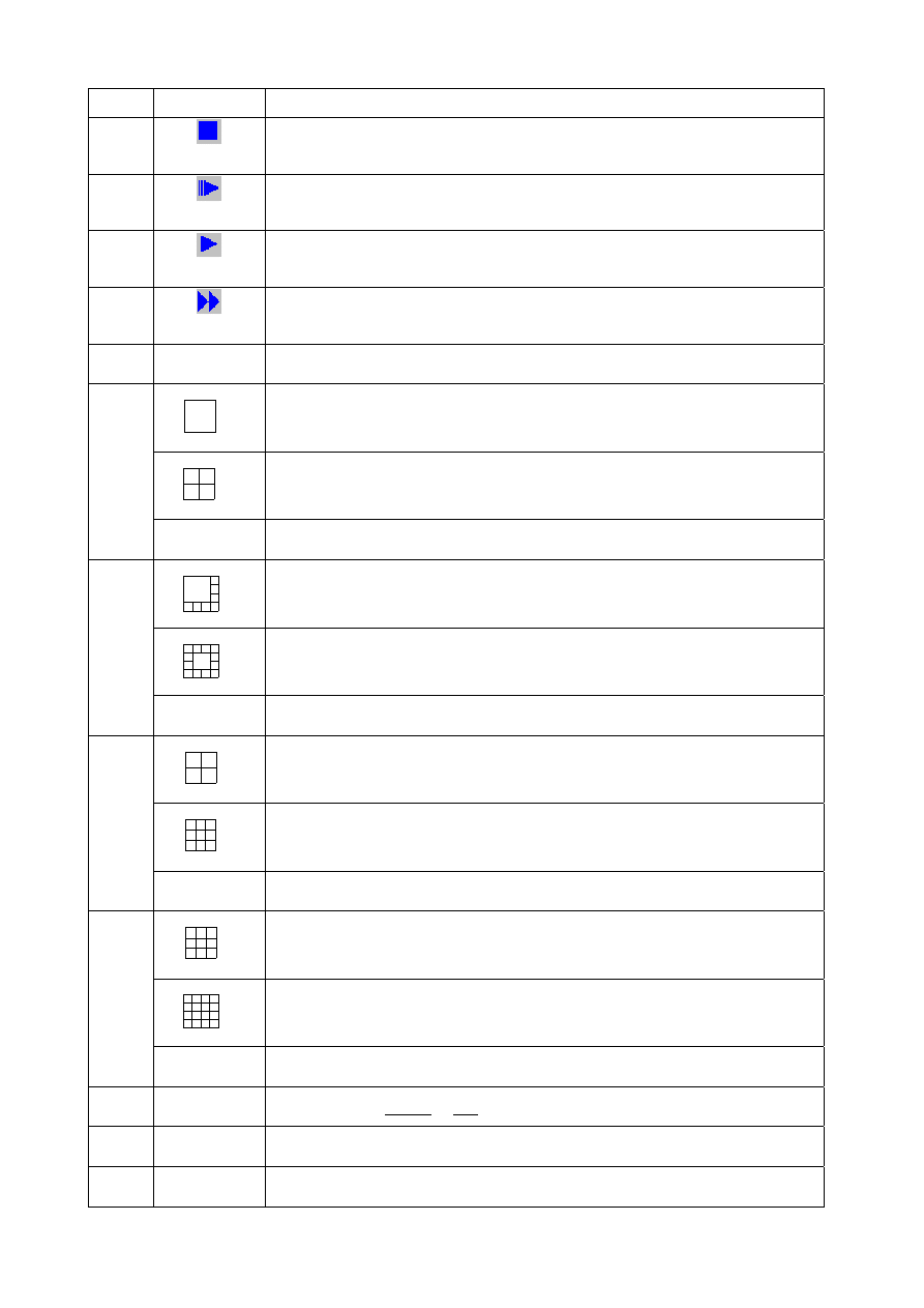
3
Field Rew
9
Stop
Press Stop to stop playback
10
Field Fwd
Press Field Fwd to pause video forward
11
Play
Press the Play button to play video forward, press the button again to
circulative change from normal speed to 1/2 speed and 1/4 speed
12
F.Fwd Search
Press F. Fwd to play video forward at high speed. Press the button again the
speed will be change circulative from ×2,×4,×6, to the highest ×8.
13
1 - 9 (1 - 16)
Press the button 9-ch DVR (16-ch DVR) to display correspond channel.
9
Select full screen of camera at 9-ch DVR model.
16
Select quad formats at 16-ch DVR model.
14
▼
Move downward or decrease the number.
9
Select 8 camera formats at 9-ch DVR model.
16
Select 13 camera formats at 16-ch DVR model.
15
◄
Move leftward or decrease the number
9
Select quad formats at 9-ch DVR model.
16
Select 9 camera formats at 16-ch DVR model.
16
▲
Move upward or increase the number.
9
Select 9 camera formats at 9-ch DVR model.
16
Select 16 camera formats at 16-ch DVR model.
17
►
Move rightward or increase the number
18
MENU
Press MENU to go into or exit main menu
19
AUTO
Press AUTO SW to switch channel by channel automatically.
20
SEL
Press this button to select the different assembled of camera formats.
4
COPY
Use this button to make video backup for CF card under play back mode.
21
ENTER
Press ENTER button to make choose or move cursor forward or make confirm
in MENU system
22 CF
Card
Slot for compact flash (CF) card.
23
HDD FRAME Location of installation for removable HDD.
Table of the button description
34
36 35
24
25
33
26
27 28 29
30
31
32
Back panel of 9-ch DVR
24
25
33
35
34
36
26
27 28 29
30
31
32
Back panel of 16-ch DVR
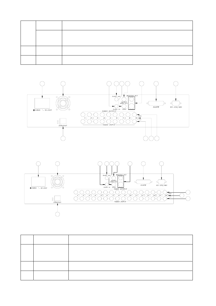
Part Label Function
24
POWER SW /
POWER
Power ON/OFF switcher.
AC90V~AC260V input.
25 FAN
Fan
26
AUDIO IN
Audio input for 1 channel

5
27
AUDIO OUT
Audio output for 1 channel
28
SPOT
SPOT Video output
29
BACKUP
VIDEO OUT
Backup video output with BNC connector.
30 MONITOR
OUT
Video output with BNC connector.
Y/C signal output with Din connector.
31
ALARM
25 pin D-Sub connector. Alarm input connector.
32
RS-232 / RS-485
9 pin D-Sub connector. For external control of unit.
33
Ethernet
RJ-45 connector for networking.
34
Video output 1 - 9
Video output 1 - 16
9-ch DVR
Camera 1 - 9 video output with BNC connector.
16-ch DVR
Camera 1 - 16 video output with BNC connector.
35
75 ohm
Switch between 75 ohm and high resistance.
36
Video input 1 - 9
Video input 1 - 16
9-ch DVR
Camera 1 - 9 video input with BNC connector.
16-ch DVR
Camera 1 - 16 video input with BNC connector.

6
CHAPTER 3
SETUP PROCEDURES
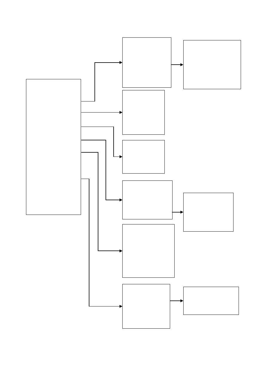
1. MAIN MENU SETUP
SETUP MENU
SYSTEM
CAMERA
MOTION
RECORD
ALARM
EVENT LIST
HDD MANAGEMENT
LOAD DEFAULT
EXIT
Press the MENU button to go into the main menu.
Use the ▲ and ▼ button to select items.
Press the ENTER button to confirm the selection.
Contents:
c
SYSTEM
d
CAMERA
System set up
Camera set up
3
MOTION
4
RECORD
Motion detection set up
Recording set up
g
ALARM
h
EVENT LIST
Alarm set up
Browse event records
i
HDD MANAGEMENT
j
LOAD DEFAULT
Hard disk management
Return to factory setting
k
EXIT
Escape from the setup menu
2.
SYSTEM SETUP
Press MENU to escape to exit the set up mode.
SYSTEM SETUP
DATE Y-M-D
2004/07/10
TIME H: M: S
10:10:10
DATA FORMAT
Y-M-D
AUTO SWITCH DWELL 02 SEC
SPOT SETUP
DATE AND TIME OSD ENABLE
SYSTEM TYPE NTSC
KEYBOARD LOCK OFF
PASSWORD MODE DISABLE
EXIT
Press the MENU button to go into the main
menu.
Use the ▲ and ▼ button to select items.
Press the ENTER button to confirm the
selection.
Contents:
c
DATE Y-M-D 2004/07/10
Use W or X button to set up date.
Press ENTER to move cursor forward.
d
TIME H:M:S 10:10:10
Use W or X button to set up time.
Press ENTER to move cursor forward.
e
DATA FORMAT Y-M-D ( M-D-Y / D-M-Y )

7
Use W or X button to select the date format.
4
AUTO SWITCH DWELL 02 SEC ( 01 – 99 )
Use W or X button to set up dwell time for auto switch.
Range from 01sec to 99 sec.
g
SPOT SETUP
Press the ENTER button to confirm the selection.
Each camera is able to be set
spot display interval time from
0 to 99 seconds individually. If
no camera is attached to the
corresponding channel then
spot channel display will skip
that channel and jump to the
next one with camera is
actually hooked on. When
motion or alarm are triggered, spot monitor will display corresponding triggered
motion/alarm channel and will jump back to spot monitoring mode when
motion/alarm period is over.
h
DATE AND TIME OSD ENABLE ( DISABLE )
Use W or X button to turn on or off the DATE AND TIME display. Where ENABLE
means display and DISABLE means no display.
i
SYSTEM TYPE NTSC ( PAL )
Use W or X button to select video system in NTSC or PAL mode.
8
KEYBOARD LOCK OFF ( TYPE1 / TYPE2 )
Use W or X button to enable or disable the keyboard lock. Totally have 3 modes as
following: OFF / TYPE1 / TYPE2.
OFF:Disable the function.
TYPE1:Only lock buttons for recording and playback, will not lock buttons for
switching display mode.
TYPE2:Will lock all buttons except menu key.
k
PASSWORD MODE DISABLE ( ENABLE )
Use W or X button to enable or disable password protection for the keyboard.
When password mode is ENABLE, there will be four blank fields for filling in the
password, use W or X button and ENTER button to select the password numbers.
l
EXIT
Escape from the SYSTEM SETUP menu
3. CAMERA SETUP
CAMERA SETUP
CAMERA CAM 01
Press the MENU button to go into the main menu.
SPOT SETUP
SPOT
SWITCHING:ON
CAM01:02 SEC
CAM09:02 SEC
CAM02:02 SEC
CAM10:02 SEC
CAM03:02 SEC
CAM11:02 SEC
CAM04:02 SEC
CAM12:02 SEC
CAM05:02 SEC
CAM13:02 SEC
CAM06:02 SEC
CAM14:02 SEC
CAM07:02 SEC
CAM15:02 SEC
CAM08:02 SEC
CAM16:02 SEC
EXIT

8
DISPLAY ON
RECORD ON
BRIGHTNESS 50
CONTRAST 50
HUE 50
COLOR 50
CAMERA TITLE 01
EXIT
Use the ▲ and ▼ button to select items.
Press the ENTER button to confirm the selection.
Contents:
c
CAMERA CAM 01 (CAM 01 – CAM 09/16
)
Use W or X button to select the camera from CAM 1 – CAM 9/16 to be adjusted or
press the button 1 – 9/16 directly.
d
DISPLAY ON ( OFF
)
Use W or X buttons to select enable to disable camera live video on screen display.
e
RECORD ON ( OFF
)
Use W or X buttons to select enable or disable camera recording for the channel.
f
BRIGHTNESS 50 ( 00-99 )
Use W or X button to adjust the brightness of the selected camera.
g
CONTRAST 50 ( 00-99 )
Use W or X button to adjust the contrast of the selected camera.
h
HUE 01 ( 00-99 )
Use W or X button to adjust the hue of the selected camera.
i
COLOR 01 ( 00-99 )
Use W or X button to adjust the color of the selected camera.
j
CAMERA TITLE 01
Use W or X button to edit the title for the selected camera. The ENTER button
move the cursor forward.
k
EXIT
Escape from the CAMERA SETUP menu
4. MOTION SETUP
MOTION SETUP
CAMERA CAM 01
MOTION DETECTION ON
BUZZER OFF
SENSITIVITY 080
AREA SETUP
EXIT
Press the MENU button to go into the main
menu.
Use the ▲ and ▼ button to select items.
Press the ENTER button to confirm the
selection.
Contents:
c
CAMERA CAM 01 (CAM 01 – CAM 09/CAM 16
)
Use W or X button to select a camera for motion detection setup. Each camera has
its own motion zone settings so they have to be setup individually.
d
MOTION DETECTION OFF ( ON )
Use W or X button to select ON or OFF for the Motion Alarm.

9
Options below will show up when MOTION is set to ON for a selected camera.
e
BUZZER OFF ( ON )
Use ◄ or ► button to select ON or OFF for buzzer on motion detection. The
buzzer will start buzzing when switch on.
.
f
SENSITIVITY 080 (001-100)
Use W or X button to adjust the level of sensitivity.
g
AREA
SETUP
Motion detection area status could be condition described as below:
The text “M” indicates motion detection for this block is activated.
Empty space indicates motion detection for this block is not activated.
Green flash block indicates current cursor position.
Use ▲ ▼ ◄ ► keys to move and “ENTER” key to change the setting.
“AUTO” key:enable 1 row, “SEL” key:disable 1 row, and green flash block will
jump to next row.
There are 6 rows and 8 columns on the screen that made up a total of 48 zones
which can be selected individually for each camera for motion detection.
h
EXIT
Escape from the MOTION SETUP menu
5. RECORD
SETUP
RECORD SETUP
NORMAL RECORD FPS 30P
ALARM RECORD FPS 30P
ALARM RECORD DWELL 10 SEC
RECORD QUALITY HIGH
AUDIO RECORD OFF
SCHEDULE RECORD ON
EXIT
Press the MENU button to go into the main
menu.
Use the ▲ and ▼ button to select items.
Press the ENTER button to confirm the
selection.
Contents:
c
NORMAL RECORD FPS 30P (60P/30P/15P/10P/5P/1P/0.5P/0P)
Use W or X button to select recording speed.
60P means 60 fields per second, which is the highest speed. Select 0P for no
recording. There is a total of 8 speeds you can choose from. (FPS: Field per second)
Note: PAL: 25P(50P/25P/12P/5P/1P/0.5P/0P)
d
ALARM RECORD FPS 30P(60P/30P/15P/10P/5P/1P/0.5P)
Use W or X button to select alarm recording speed when external alarm or motion
detection is triggered.
Note: PAL: 25P(50P/25P/12P/5P/1P/0.5P)
e
ALARM RECORD DWELL 10 SEC ( 5 - 99 )
Use W or X button to set the dwell time for alarm recording when external alarm or
motion detection alarm is triggered.

10
f
RECORD QUALITY BEST ( HIGH / MEDIUM / LOW )
Use W or X button to select the BEST, HIGH, MEDIUM or LOW setting so there is
a total of four levels of recording quality that can be chosen from. The higher the
quality, the higher the amount of storage will be consumed. Thus, this setting
should be carefully chosen as it will affect the usage of hard disk storage.
A table of relationship between quality, record speed and hard disks is attached for
reference.
g
AUDIO RECORD ON ( OFF )
Use
W or X button to select ON/OFF audio recording
h
SCHEDULE RECORD ON ( OFF )
Use W or X button to select ON/OFF. Press the ENTER button to confirm the
selection.
Schedule recording has highest priority in recording process. When schedule
recording is in process, stop recording can not be performed by pressing “REC”
button. You must manually enter the DVR system menu to stop schedule
recording before pressing “REC” button for manually stop recording.
“REC” button force recording can be performed only when schedule recording set
“X” for no recording on its schedule. Totally divided by 24 hours.
O:Full recording
A:Alarm recording
X:No recording
i
EXIT
Escape from the RECORD SETUP menu
6. ALARM SETUP
ALARM SETUP
BUZZER
BUZZER/ALARM DWELL 05 SEC
VIDEO LOSS ALARM ON
AUDIBLE ALARM ON
EXT. ALARM MODE LOW
ALARM DISPLAY MODE DISABLE
MOTION EVENT OFF
RELAY
EXT. ALARM RELAY ON
VIDEO LOSS RELAY ON
MOTION RELAY ON
EXIT
Press the MENU button to go into the
main menu.
Use the ▲ and ▼ button to select
items.
Press the ENTER button to confirm the
selection.
SCHEDULE RECORD
O O O O O O O O O O O O O O O O O O O O O O O 1
Ç Ç Ç Ç Ç Ç Ç Ç Ç
0 3 6 9 12 15 18 21 24
O:FULL REC
A:ALARM REC
X:NO REC

11
Contents:
c
BUZZER/ALARM DWELL 05 SEC ( 5 - 99 )
Use W or X button to adjust the duration time of the buzzer action.
d
VIDEO LOSS ALARM ON ( OFF )
Use W or X button to set up video loss alarm enable or disable..
When video single is lost, the buzzer will act immediately and the screen will
be switched to 9/16 format, also at the same time a record with LOS ID will be
added to the event list but no video will be storage.
e
AUDIBLE ALARM ON ( OFF )
Use W or X button to enable or disable the buzzer.
f
EXT. ALARM MODE LOW ( HIGH )
Use W or X button to select what kind of input signal to trigger the alarm.
( HIGH - input signal changes from LOW to HIGH
LOW – input signal changes from HIGH to LOW).
g
ALARM DISPLAY MODE DISABLE ( ENABLE )
Use ◄ key or ► to select disable or enable. Channel display will jump to
corresponding motion or alarm triggered channel when turning enable. No action
will be taken when turning disable.
h
MOTION EVENT OFF ( ON )
Use ◄ key or ► to select on or off. Motion even will be recorded into even list
when turning on, no motion events will be recorded when turning off.
i
EXT. ALARM RELAY ON ( OFF )
Use ◄ key or ► key to select on or off. Relays will take auction on external alarm
when turning on, no auction on relays when turning off.
j
VIDEO LOSS RELAY ON ( OFF )
Use ◄ key or ► to select on or off. Relays will take auction on video loss when
turning on, no auction on relays when turning off.
k
MOTION RELAY ON ( OFF )
Use ◄ key or ► to select on or off. Relays will take auction on motion detection
when turning on, no auction on relays when turning off.
l
EXIT
Escape from the ALARM SETUP menu
7.
EVENT LIST
EVENT LIST PAGE 1
NO YY / MM / DD HH:MM:SS CH ALM
01 04 / 07 / 10 11:11:25 05 MOT
02 04 / 07 / 10 11:11:15 02 LOS
03 04 / 07 / 09 22:22:10 15 EXT
03 04 / 07 / 09 10:10:10 -- REC
03 04 / 07 / 09 08:00:55 -- PWR

12
Use ▲ or ▼ button to select the item. It can display 10 records in a page.
Use X button to go into next page. Use W button to go into front page.
Press the ENTER button to execute the event’s playback.
NO:
the number of event list, maximum 3000 records.
YY / MM / DD:
Year / Month / Date
HH : MM : SS:
Hour / Minute / Second
CH:
Correspond with camera.
ALM
: Alarm type.
There are five alarm types including image lost (LOS), external alarm (EXT), record start
(REC), motion detected (MOT)
and power on (PWR).
8. HDD MANAGEMENT
HDD MANAGEMENT
OVERWRITE MODE OFF
CAPACITY WARNING 20%
HDD FORMAT SETUP
EXIT
DISK CAPACITY LEFT RATIO
A 250GB 100%
B NONE NONE
Press the MENU button to go into the main
menu.
Use the ▲ and ▼ button to select items.
Press the ENTER button to confirm the
selection.
Contents:
c
OVERWRITE MODE OFF ( ON )
Use W or X button to enable or disable overwriting when HDD is full. When HDD
overwrite is enabled, the oldest partition on the HDD will automatically be reused,
that means the oldest images will be overwritten by the current images. There are a
total of 10 partitions automatically created on every HDD during the HDD format
process. When overwrite mode is disabled, the Full Warning percentage selection
will be appeared and need to be configured.
d
CAPACITY WARNING 20% (15% / 10% / 5%)
Use W or X button to select one of the four settings (20%, 15%, 10%, 5%). The
default is 20%. The buzzer will turn on when free space left in the HDD go below the
set value and it will on again when the total free space left go below 5%. The value
of percentage of total free space in the system will be displayed on the top left corner
of the screen when HDD free spaces go the set value.
e
HDD FORMAT SETUP
Use ENTER button to enter the HDD FORMAT SETUP menu.
HDD FORMAT SETUP
HDD PASSWORD PROTECT DISABLE
FORMAT
EXIT

13
A password can be setup to protect the hard disk content. When the HDD
PASSWORD PROTECT
set to ENABLE, a password needs to be entered in order
to perform a hard disk format. Of course this password you can setting same as the
“system’s password” or different. Initial number is 1111.
HDD FORMAT SETUP
HDD PASSWORD PROTECT ENABLE
HDD PASSWORD 1 1 1 1
FORMAT
EXIT
When you choose HDD FORMAT and press the ENTER button, following screen
will be displayed:
DATA WILL BE LOST
PROCEED WITH FORMAT? ( NO)
Use W or X button to choose (YES) proceeded to the HDD format or (NO) to return
to the previous manual. If the HDD would not go on proceeding with format, choice
(NO) and press ENTER or MENU to exit. To confirm and go ahead with HDD format,
choose (YES) and press ENTER. It has to wait a short period of time in order for the
HDD to format. Then screen will return to the MAIN MENU when finished.
f
EXIT
Escape from the HDD MANAGEMENT menu.
g
DISK CAPACITY LEFT RATIO
To display the situation for all HDD.
DISK CAPACITY
LEFT
RATIO
A 250GB
100%
B NONE
NONE
DISK A/B:Maximum for 2 HDD.
CAPACITY:Capacity for each HDD NONE is with no HDD.
LEFT RATIO:Ratio for each HDD. NONE is with no HDD.
9. LOAD DEFAULT
Use the ENTER button to return to the factory default. This will clear all the user settings and
replace it with the original default parameters.
10. EXIT
Exit from the SETUP MENU.

14
CHAPTER 4
OPERATION PROCEDURES
1
Getting Started with your machine
Please assure the following instructions before you switch on the machine:
1.1 Voltage check: Before power cable is connected, please check the voltage of this
appliance against the supply. Two Voltages options, 115V or 230V, can be selected at the
back of the machine.
CAUTION
- Damage would be caused if incorrect power voltage applied.
1.2 Hard Disk connection: Make sure the 40-Pin Hard Disk Data cable and the 4-Pin power
connectors are properly connected.
2 Recording
Manual operation
Press the REC key to enter the Recording Mode and the red indicator on front panel will be lit
which indicate the system is currently in Recording Mode. To stop recording, press the
REC
key again.
For more information on Setting up Recording Mode, refer to Chapter 3 Recording Setup
In Recording Mode, if there is a power failure or power lost for any reasons that cause a
shut down of this machine, it will be back to the Recording Mode automatically when
power restored.
The color of the camera title indicates the camera channel current status, red color
indicates recording is in process for the camera and white color indicates no recording.
When schedule recording is performed, recording process will follow its own schedule to
start or stop recording.
Attention: When schedule recording is in process, the recording process will not be able to
stop by pressing REC button. You must manually enter the system menu to stop the
recording.
3 Playback
3.1 Time
search
Press ►Play button to play video forward and ◄Rew button to play video reverse. After
you press the either ►Play or ◄Rew button, a message “PLAY BACK START TIME
SETUP
” will be displayed on the screen.
You can press (►) or (◄) button to select the item that you wanted to set up and press
(▲/▼) button to increase or decrease the numbers. After playback start time has been set
up, press the ENTER key to start.
Press ■Stop button to resume the Live Mode.
3.2 Events
search
A maximum of 3000 events can be stored in the Event List. For more information about

15
events search, Please refer to Chapter 3 Event List. (Page 10)
3.3 High-Speed Forward and Reverse Search
High-Speed Forward Search
In playback mode, after pressed the ►Play button to play video forward. For high-speed
forward, presses the ►► button will double the forwarding speed. The fastest speed is 8
times than normal.
Reverse Search
Press the ◄Rew button to reverse playback video. For high-speed reverse, presses the
◄◄ button to double the reversing speed. The fastest reverse speed is 2 times than
normal.
3.4 Still Playback (field by field)
This function can only be used in full screen mode, which is not available in Quad Mode or
other Multiple Frames Mode. The ◄││ and ││► buttons are used to enter the Still
Playback mode and press them again to advance or record the picture field by field. The
◄││ or ││► sign will be displayed on the top left corner of the screen.
3.5 Stop
Playback
Press the ■ Stop button to leave playback mode and resume the Live Mode.
4.
Audio recording and playback
When audio recording setting is on under video recording setting, audio recording will be start
automatically. Audio replay will only available under video replay in normal speed. In video
recording speed of 15P (12P), 30P (25P) and 60P (50P), you will get continuous audio
playback. If video recording speed is under 5P, then poor audio recording quality may occur.
5.
Network function
Network function is an optional for this DVR. Please make sure that your DVR does come with
this network function. The network setting can only be configured through network remote
computer. Please refer to network setting instruction for detail information. DVR network
function provides real time surveillance, PTZ control and recording remotely under network
basis.
6.
Hard disk and CF Card recommend
Maximum 4 pieces and at lease one hard disk should be connect, the capacity of hard disk from
10GB to 250GB for each.
When you restart the power of this appliance after install or replace new hard disk it will be
format automatically, we been tested the follow model of hard disk and recommend you use
when you install by yourself. Removable HDD must setting Master.
Brand Model Capacity
Speed
(rpm)
Seagate ST3120023A
120GB 7200
rpm
Seagate ST380020A
80GB
7200
rpm

16
Maxtor 6Y120L0
120GB 7200
rpm
Maxtor 6Y160P0
160GB 7200
rpm
Seagate ST3160023A
160GB 7200
rpm
Maxtor 7Y250P0-A
250GB 7200
rpm
We
DO NOT
suggest Samsung hard drive base on technical examination
CF Card Brand
Capacity
Transcend 128M
Transcend 256M
TOSHIBA 128M
7.
Backup
The DVR support 2 methods for backing up:
1. VCR Backup
9ch & 16ch DVR
provide composite signal output for back -up use. You can keep the Image
data, by selecting a particular channel, and simply just connected BNC connector, at the Back
Panel of 9ch & 16ch DVR, with VCR Connector. Press VCR REC button, after decided which
channel and what recording data need to keep, during Play-Back Mode.
2. Compact Flash (CF) Card Backup
CF card backup is attached function of DVR network adapter; please ensure your DVR comes
with network function before using CF card backup.
It could be 2 file formats for CF card backup c Single picture JPEG file d Video clip AVI file
It takes awhile on DVR system to be ready after CF card insertion. A CF mark will show up on
top right screen under playback mode which indicates DVR system is ready for CF backup.
You will only able to make CF card backup under single channel full screen playback mode
c
. Single picture JPEG file
Run the DVR under playback mode and switch to the channel you are going to backup
Press “PAUSE” button then press “COPY” key to back a single image into JPEG file on a CF
card. The screen will first shows up CF CARD TESTING PLEASE WAIT which indicates the
DVR is initializing and perform CF card testing for CF card backup and It takes around 1 second.
Message BACKUP TO CF CARD PLAESE STOP ANY UNNECESSARY JOBS will appear next
in the middle of the screen and message example CF Card USED/CAPACITY:23MB/121MB will
appear in the bottom of the screen which indicates 23M mage byte out of 121 mage byte are
used in the CF card. The single image CF card backup has been done successfully when all
messages are disappeared.
d
. Video clip AVI file
Run the DVR under playback mode and switch to the channel you are going to backup (you are
not allowed to perform CF card backup on single channel mode if your DVR recoding in quad
mode) If you press “COPY” key under multiplexer recording mode with quad playback the
screen will shows up PLEASE TURN TO FULL SCREEN MODE to remind you to switch to

17
single channel mode.
Press “COPY” key to start backup a video clip images into AVI file under full screen normal
speed playback mode. The screen will start showing BACKUP TO CF CARD AVI FILE on top of
the screen for around 1 second and then appear AVI message in the left bottom screen which is
indicating DVR system is currently backing up video into buffer. Press “COPY” key again to
terminated video backup on your ideal period, the screen will show up CF CARD
PROCESSING PLEASE WAIT .. . It takes around 1 min to save AVI file into CF card, it depend
on how big the file will be.
If the backup procedure has been done successfully, the message “CF CARD PROCESSING
PLEASE WAIT ….” will disappear and the message SAVE OK showing up.
If the backup action is failed, screen will show SAVE FAIL PLEASE CHECK CF CARD It could
be 2 possibilities.
a. DVR causes internal error on buffer, please wait for 30 seconds and redo backup
procedure again.
b. Improper CF card insertion or connection shortage, please unplug your CF card and
put it back into CF card slot again.
Any CF card removal will trigger internal buzzer and message CF CARD REMOVED will shows
up on the screen.
When insufficient capacity occurred then message WARNING CF CARD INSUFFICIENT
CAPACITY will shows up, please busing your PC to free up some space on the CF card before
backup.
Using CF card reader to read images backup on a CF card as procedure below:
Hook up CF card USB adapter to the USB port on PC.
Follow the on CD instruction and install necessary driver files into your PC.
Insert the CF card into the card reader.
8. Alarm control
There are three types of alarms that the system can be configured to handle. They are Motion
detection Alarm, External Alarm and Video Loss Alarm.
1.
Motion detection Alarm and External Alarm:
When motion detection or External Alarm was triggered, there are 5 possible actions will be
taken.
a. Changes recording speed as alarm recording speed. please refer to Chapter 3 Function
5, Recording Setup
b. Monitor will display corresponding full screen alarm channel, it will switch automatic
mode to manual mode if buttons pressing activity occurred within 5 seconds.
c. Relays can be activated by motion detection or external alarm when turning on.
d. External alarm will be recorded in event list. Motion detection can be setting yes or no.
e. The camera title will be transformed into color of yellow when motion is happening,

18
“ALARM” text will show up when external alarm is triggered.
2. Video
Loss
Alarm
Video Loss alarm is enabled as default and cannot be changed. Although buzzer action can
be disabled, an ALM record will still be added to the Event List that indicates the exact time
of video loss. For setting up video loss alarm, please refer to Chapter 3 Function 6 Alarm
Setup.
9. External alarm connector
A DB-25 connector is used for external alarm input. It will accept TTL/CMOS type trigger signals
where the 9ch & 16ch DVR alarm inputs will be set by signal polarity. It also accepts contact
type devices. For example, N.O. relay input, the Alarm Polarity should set to LOW in the ALARM
SETUP menu. For N.C. relay input, the Alarm Polarity should set to HIGH in the ALARM SETUP
menu.
Connector pins 1-16 are for TTL/CMOS compatible alarm signals or for connect one side of the
contact type devices. Connector pins 20-21 are for input signal grounding or the remaining side
of the contract type devices.
The alarm hold input accept TTL/COMS alarm signal as well as contract device. The connector
pin 22 connected to Alarm Reset. The Alarm Reset signal return connects to ground pin (pin
20-21).
Alarm output is Relay Type, Pin 23 is Normal Close and Pin 25 is Normal Open. These outputs
can be used to control external devices.
DB-25
Pin 1-9, (1-16)
Alarm 1-Alarm 9 (16) Camera alarm input
Pin 9-19, (17-19)
N/A
Pin 20, 21
GND (connecting to ground)
Pin 22
Alarm Reset
Pin 23
Alarm output, N.C.
Pin 24
Relay COM
Pin 25
Alarm output, N.O.
10. RS-232/RS-485 connector
DB-9: RS232 Pin 2 -----RXD
Pin 3 -----TXD
Pin 5 -----GND
RS-485 Pin 6 -----RXDA
Pin 7 -----RXDB
Pin 8 -----TXDZ
Pin 9 -----TXDY
19
11 RS-232/RS-485 control protocol
Data format: Data : 8 bits
Parity: None
Start bit: 1
Baud : 9600
Totally 3 bytes in data frame:
1. Byte=0x10 :command of initialize
2. Byte=Refer to below table :command for each key string
3. Byte=first byte plus second byte :command for confirm checksum
9-ch DVR
16-ch DVR
Command
9-ch DVR
16-ch DVR
Command
F.Rew
F.Rew
0x38
Rew
Rew
0x3a
Field Rew
Field Rew
0x3b STOP
STOP
0x3c
Field Fwd
Field Fwd
0x3d
PLAY
PLAY
0x39
F.Fwd F.Fwd
0x3e
0x32
0x31
0x33
0x34
ENTER ENTER
0x35
AUTO
AUTO
0x37
SEL SEL
0x36
1 1
0x11 2 2
0x12
3 3
0x13 4 4
0x14
5 5
0x15 6 6
0x16
7 7
0x17 8 8
0x18
9 9
0x19
10
0x1a
11
0x1b
12
0x1c
13
0x1d
14
0x1e
15
0x1f
16
0x30
PS:REC & MENU:No control command

20
SPECIFICATIONS of 9-ch DVR
Model No.
DRE-S0931 DRE-S0931P
Video System
NTSC
PAL
OSD Language Selection
English or Other
Operation Mode
Triplex
Date & Time Generation
Yes
Video Loss Detection
Yes
Password Protection
Yes
Motion Detection
48 Target per camera
System
Power Failure Alarm
Yes
Compression Format
Wavelet
Display Resolution
720 x 480
720 x 576
Recording/Playback
Resolution
720 x 240
720 x 288
Display Rate
270 Fields Per Sec
225 Fields Per Sec
Recording Rate
60 Fields Per Sec
50 Fields Per Sec
Playback Rate
60 Fields Per Sec
50 Fields Per Sec
Recording Mode
Schedule / Manual / Alarm / Motion
Recording Quality
Best / High / Medium / Low
Playback Search
Event / Time
Image
Processing
Display/Playback Mode
Full Screen / Quad
Interface Ethernet(TCP/IP),RJ-45 Connector
Recording/Display/Playback
Yes ( IE Browser )
Network
Remote Backup
Yes ( IE Browser )
Video Storage
No HDD(Standard),expand up to Built-in 1 HDD and Removable 1 HDD
( 40-250 GB for each HDD ) (Optional)
Storage
HDD Recording Mode
Auto Overwrite or Stop when it is full
Backup
Device
VCR (Optional) / CF Card / IE Browser
Audio Input/Output
Input 1 CH / Output 1 CH
Alarm Input/Output
Input x9 (NO/NC) / Output x1 (NO)
Input
Composite 1.0 Vp-p 75 ohm BNC x 9
Output
Composite 1.0 Vp-p 75 ohm BNC x 2 (Main/Call Monitor)、Backup
Output(BNC) x 1、S-Video x 1
Video
Looping
Composite 1.0 Vp-p 75 ohm BNC x 9
I/O
RS-232/RS-485 Yes
Power
AC 90~260V , 50/60Hz
Power Consumption
21W (1 x HDD Load)
Operation Temp.
5 ~40 (41 ~104 )
℃
℃
℉
℉
Operation Humidity
Less then 90%
Unit Dimension
430(W) x 88(H) x 380(D) mm
Packing Dimension
516(W) x 173(H) x 544(D) mm
Net Weight
8Kg (No HDD)
Mechanism
& Electric
Gross Weight
9Kg (No HDD)
Removable HDD Case
1 Set
Accessory
HDD Bracket
Built-in 1 set

21
SPECIFICATIONS of 16-ch DVR
Model No.
DRE-S1631 DRE-S1631P
Video System
NTSC
PAL
OSD Language Selection
English or Other
Operation Mode
Triplex
Date & Time Generation
Yes
Video Loss Detection
Yes
Password Protection
Yes
Motion Detection
48 Target per camera
System
Power Failure Alarm
Yes
Compression Format
Wavelet
Display Resolution
720 x 480
720 x 576
Recording/Playback
Resolution
720 x 240
720 x 288
Display Rate
480 Fields Per Sec
400 Fields Per Sec
Recording Rate
60 Fields Per Sec
50 Fields Per Sec
Playback Rate
60 Fields Per Sec
50 Fields Per Sec
Recording Mode
Schedule / Manual / Alarm / Motion
Recording Quality
Best / High / Medium / Low
Playback Search
Event / Time
Image
Processing
Display/Playback Mode
Full Screen / Quad
Interface Ethernet(TCP/IP),RJ-45 Connector
Recording/Display/Playback
Yes ( IE Browser )
Network
Remote Backup
Yes ( IE Browser )
Video Storage
No HDD(Standard),expand up to Built-in 1 HDD and Removable 1 HDD
( 40-250 GB for each HDD ) (Optional)
Storage
HDD Recording Mode
Auto Overwrite or Stop when it is full
Backup
Device
VCR (Optional) / CF Card / IE Browser
Audio Input/Output
Input 1 CH / Output 1 CH
Alarm Input/Output
Input x16 (NO/NC) / Output x1 (NO)
Input
Composite 1.0 Vp-p 75 ohm BNC x 16
Output
Composite 1.0 Vp-p 75 ohm BNC x 2 (Main/Call Monitor)、Backup
Output(BNC) x 1、S-Video x 1
Video
Looping
Composite 1.0 Vp-p 75 ohm BNC x 16
I/O
RS-232/RS-485 Yes
Power
AC 90~260V , 50/60Hz
Power Consumption
21W (1 x HDD Load)
Operation Temp.
5℃~40℃ (41℉~104℉)
Operation Humidity
Less then 90%
Unit Dimension
430(W) x 88(H) x 380(D) mm
Packing Dimension
516(W) x 173(H) x 544(D) mm
Net Weight
8Kg (No HDD)
Mechanism
& Electric
Gross Weight
9Kg (No HDD)
Removable HDD Case
1 Set
Accessory
HDD Bracket
Built-in 1 set

22
TIME LAPSE RECORD TIME
The record time is different based on record speed and record quality. Please refer to the
following table.
80GB Hard Disk
FPS
(field per sec.)
60 / 50
30 / 25
15 / 12
10
5
1
0.5
Best
8 hr
16 hr
32 hr
48 hr
96 hr
480 hr
960 hr
High
14 hr
28 hr
56 hr
84 hr
168 hr
840 hr
1680 hr
Middle
20 hr
40 hr
80 hr
120 hr
240 hr
1200 hr
2400 hr
Record
Quality
Low
25 hr
50 hr
100 hr
150 hr
300 hr
1500 hr
3000 hr
160GB Hard Disk
FPS
(field per sec.)
60 / 50
30 / 25
15 / 12
10
5
1
0.5
Best
16 hr
32 hr
64 hr
96 hr
192 hr
960 hr
1920 hr
High
28 hr
56 hr
112 hr
168 hr
336 hr
1680 hr
3360 hr
Middle
40 hr
80 hr
160 hr
240 hr
480 hr
2400 hr
4800 hr
Record
Quality
Low
50 hr
100 hr
200 hr
300 hr
600 hr
3000 hr
6000 hr
240GB Hard Disk
FPS
(field per sec.)
60 / 50
30 / 25
15 / 12
10
5
1
0.5
Best
24 hr
48 hr
96 hr
144 hr
288 hr
1440 hr
2880 hr
High
42 hr
84 hr
168 hr
252 hr
504 hr
2520 hr
5040 hr
Middle
60 hr
120 hr
240 hr
360 hr
720 hr
3600 hr
7200 hr
Record
Quality
Low
75 hr
150 hr
300 hr
450 hr
900 hr
4500 hr
9000 hr
500GB Hard Disk
FPS
(field per sec.)
60 / 50
30 / 25
15 / 12
10
5
1
0.5
Best
50 hr
100 hr
200 hr
300 hr
600 hr
3000 hr
6000 hr
High
88 hr
176 hr
352 hr
528 hr
1056 hr
5280 hr
10560 hr
Middle
125 hr
250 hr
500 hr
750 hr
1500 hr
7500 hr
15000 hr
Record
Quality
Low
156 hr
312 hr
624 hr
936 hr
1872 hr
9360 hr
18720 hr
CF Card Backup time
Capacity=128M
Single Image file size
Single picture JPEG file
Video clip AVI file
40K
3100 fields
25 minute
50K
2500 fields
20 minute
60K
2000 fields
16 minute

23
Wyszukiwarka
Podobne podstrony:
AT MIO 16 User Manual
Monitor 16 9 22 cale Acer AL2202W User Manual
cas test platform user manual
CARPROG Opel ECU programmer user manual
elm327 interface viecar obd2 bluetooth scanner user manual
autel power scan ps100 user manual
Chartplanner user manual
INPA User manual
all100 user manual
CARPROG user manual
FX2N 485 BD User's Manual JY992 Nieznany
mb sbc tool user manual
07 Altistart48 user manual
iphone user manual pdf
PRDM 0010 Upgrade user manual UPG 0001
TK105 GPS Tracker User Manual
ATDSK1118 User Manual
FX2N 232 IF User's Manual JY992D66701
więcej podobnych podstron