Valve Adjustment
The procedure here is not meant to replace the shop manual procedure for valve adjustment.
If you feel that it might be harmful to your engine do not follow this procedure.
Several have done it this way and found it to be helpful.
Thanks for the help Dave M. and Scott B.
Place bike on a lift if available or stand to hold bike straight up if possible.
Remove 3 allen bolts holding instrument cluster, disconnect connectors or fold instrument
cluster back over handlebars using soft cloth to keep from scratching the finish.
Turn fuel petcock to off position, remove fuel line (lower left hand side of tank)
Remove fuel tank vent hose upon top of tank.
Remove rider seat and unplug the green electrical connector at rear of fuel tank.
Remove long bolt and nut at rear of tank. (10mm)
Grasp tank and gently pull backwards with a slight wiggling motion, tank should
slide back a few inches and lift up. Set aside on a towel.
Remove two hoses on top of rear cylinder and fold back out of way.
Remove spark plug wires from plugs and tie back.
DO NOT REMOVE SPARK PLUGS AT THIS TIME
Removes possibility of dropping a bolt in an open hole.
Break loose allen head bolts on top of valve covers and remove using a 5mm allen wrench.
Clearance between the frame and top of valve covers is close and a ball allen wrench is very
helpful when removing screws.
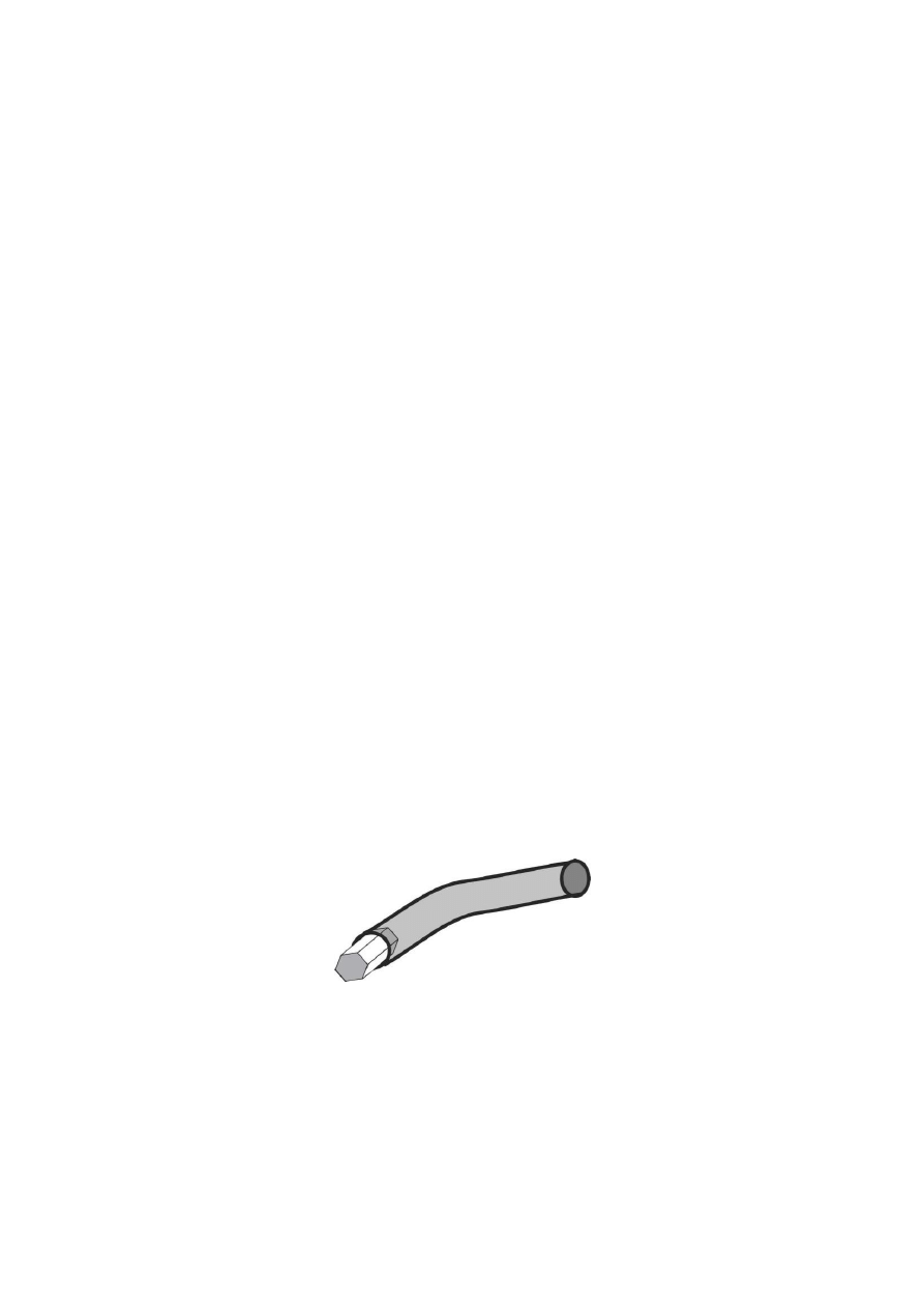
If you do not have a ball allen wrench, saw off a 1/2" long piece of the proper size allen wrench
and force into a 6" long piece of 1/8" rubber or vinyl hose.
This allows you to get into a tight area and back out the screws by twisting the hose.
Remove the spark plug on the right hand side of cylinder.
Careful to not drop anything in hole from here out.
Placing tissue or a rag would be advised over hole.
Lift up on covers and remove paying attention to (2) dowel pins used to index
cover to cylinder spacers, they will either lift out with cover or remain in
spacer.
Be careful as not to damage gasket.
Yes it can be re-used if you are careful
with it!
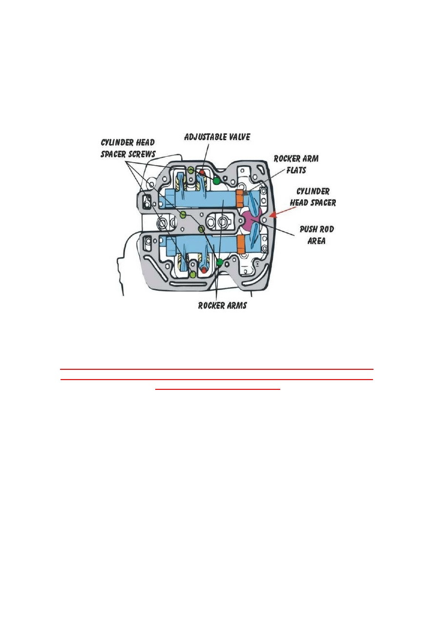
To gain easier access to adjuster screws on rocker arm fingers, remove
cylinder head spacer plates also. They are held on by (6) screws as
indicated by green dots. (5mm allen head)
The Spacer also has it's own set of indexing dowels and gasket.
Here's a time saving tip:
The piston doesn't have to be at true TDC to adjust the valves.
Removing that left side cover is a real pain.
If you do not feel that you can safely do the next step, remove the left-hand
side cover and floorboard and use a socket on the crank to turn the engine
around to the proper location.
Pull the two outside front and rear spark plugs then blip the starter until you
see the valves on one cylinder go fully closed.
(The 4 stroke cycle - as the engine fires and the piston travels down both sets
of valves are closed.
As the piston travels upward the EXHAUST valves are opened and expel
the burnt gasses.
As the piston goes over Top Dead Center the INTAKE valves open and
fuel enters the chamber and the piston travels downward.
The intake valves close and the piston again travels upward and this is
the COMPRESSION STROKE, when the piston gets to TDC, this is where
you want the piston to be to adjust the valves.)
You'll notice that there is a small period when the valves don't move at all.
You can then raise the arms slightly using a wrench on the rocker arm flats at
the push rod end of the rocker shaft and compressing the lifter slightly.
Also, sticking a dowel down the spark plug hole when you think it's about right
will confirm that the piston is at the top.
Just be sure to pull it out before touching the starter again.
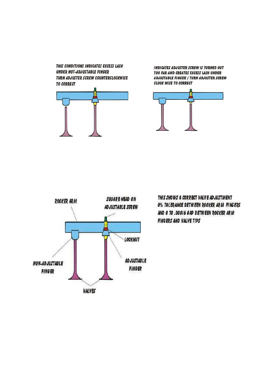
Loosen the lock nut on the adjuster screw. (10 mm hex head) back the adjuster
screw (aprox 1/8" square head) out until it is loose, then run it down with your
fingers until it just touches the valve
*(remember, your fingers are amazingly sensitive)
then while holding the adjuster securely with one wrench tighten the lock nut
with another.
Using a dial indicator for true "0" tolerance
Either have a magnetic block, or a fixture that you can screw down, or clamp
your indicator in place. If you have a magnetic base, there is a good spot where
the riders seat locks into the frame to place the base for the rear cylinder.
Another good spot is the frame where your VIN sticker is for the front cylinder.
I rested the tip of the dial indicator on the rocker arm over the push rod tubes.
(indicated by a dark blue area in the second diagram.)
Use your own discretion if you find it easier to place it at another spot.
The further out from the axis point on the rocker arm will give a better reading.
Loosen the adjusting screw on the rocker arm and back it out until the non
adjusting side is flush. Then set the indicator to zero.
Then adjust the screw down by hand until you see the indicator start to move.
Adjust the screw until it is in contact, and the indicator reads zero.
Then tighten the locking nut.
To Check:
Use a feeler gauge (size doesn't matter).
Place the feeler gauge under one side and check the gauge.
If say for example, it reads 10/10,000ths, I remove it and check the other side. If
the other side also reads 10/10,0000, then I know both sides are identical,
which means when you remove the feeler gauge they are both flush at exactly
0 tolerance.
It is fool proof, and guarantees a true "0" tolerance setting.
The slight "ticking" which can be heard at the valve covers when the valves are
properly adjusted is perfectly normal and is merely the sound of the valves
closing on their seats.
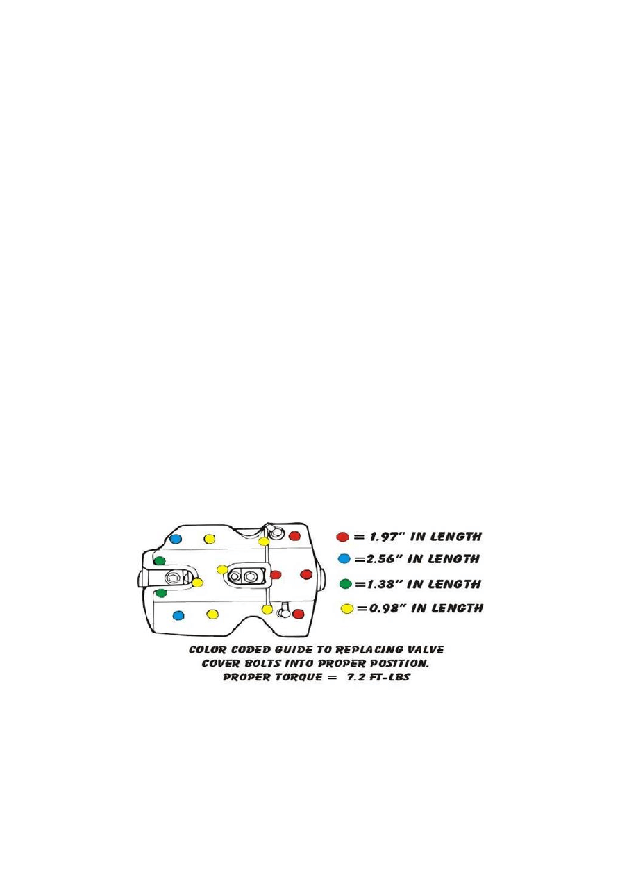
Almost forgot, when putting your valve covers back on this diagram might be
of help.
Wyszukiwarka
Podobne podstrony:
road star accelerator pump adjust
road star maintenance tips
DR650SE Valve Adjustment
road star dowel pin ettiquette
road star cure backfire
road star cams replacement procedure
road star fat bak
0560 Adjusting valve clearance
0560 Adjusting valve clearance
crm star
Dawning Star Terraformer 07 Trains of Eos
Dawning Star Terraformer 01 Daybringer Prestige Class
Fringeworthy Star System Survey Form
Dawning Star Terraformer 10 Eotian Air Carriers
Dawning Star Terraformer 12 Invisibility Tech
ZF5hp24 valve body TSB
041 Star system, czyli Filmowy Olimp
mb star c3 self test manual
więcej podobnych podstron