
Cam Replacement Procedure
written up by John Weber
Removing Fuel Tank
1. Place the bike on a stand or lift.
2. Remove the three allen bolts holding the instrument panel to the
tank.
3. While leaving the two wire harnesses connected, hang the
instrument panel over the handlebars making sure to use a towel
to protect from scratching.
4. Turn the fuel valve off. Disconnect the fuel hose aft of the valve
while holding a rag in one had to prevent residual fuel from
dripping on the bike.
5. At the rear of the tank, disconnect the small green electrical
connector.
6. Disconnect the air breather tube at the front of the tank.
7. Remove the long through bolt at the rear of the tank and set
aside.
8. Using both hands slowly pull tank towards the rear of the bike to
dislodging from the rubber forward mounts.
9. Set tank out of the way.
Removing the Timing Left side Cover
1. Using a phillips screw driver, remove the two screws holding the
kick stand kill switch and let hang.
2. Using an allen driver, remove the six bolts holding the gray
cover. (Note that two of the bolts are two different lengths. Make
sure you remember where they came from.)
3. Remove the two black plastic plugs with a large slotted
screwdriver. Be careful not to lose the "O" rings. Set aside. You
will come back to this area of the bike when you're ready to
adjust the valves for clearance to close up.
Removing the Valve Covers, Valve Cover Extensions,
and Loosening the Rocker Arm Bases on Both Cylinders
1. Disconnect the two black rubber hoses going to the rear valve
cover. (#1 cylinder by the way). Stow out of the way.
2. Disconnect the four spark plug wires and stow them out of the
way.
3. Loosen, (do not remove) one spark plug in each cylinder. (Very
lose, but not out. This will allow you to turn the engine over
when the time comes.)
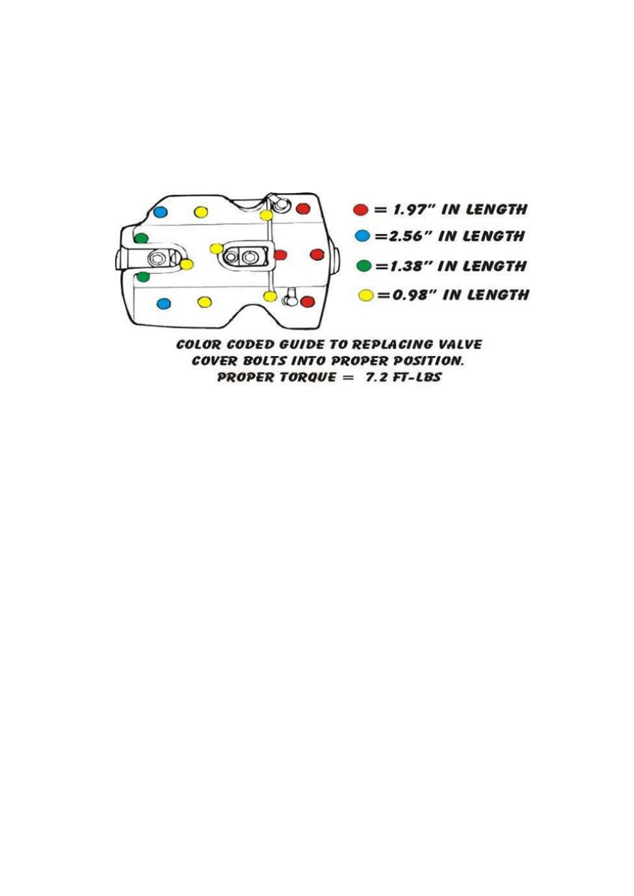
4. Remove all 12 hex bolt holding the chrome valve cover on.
(Both cylinders.) Don't worry about that there are several
different lengths. In Tid
y’s maintenance hints,
they have a color picture telling you exactly where they go
back.
5. Now carefully slide out the chrome covers from both the front
(#2) and the rear (#1cylinder). You must lift up a little to get
them out.
6. There are two chrome pins (keying devices if you will) that
either are stuck to the covers you've taken off, or they are still
in the next chrome piece (valve cover spacer). Find them,
remove them and set aside. (This is why you left the spark
plugs just lose and not out. Can you imagine if you dropped
them in the cylinder holes!)
7. Next, remove the metal like cover gasket from each cylinder
making sure not to bend, staple or mutilate. These will be
reused. Set aside.
8. Next, remove the 6 bolts holding the valve cover spacer on.
Again, under them are two more of these chrome key way pins
and gaskets. Do as you did in the previous steps. Keep the
bolts, pins, and gaskets segregated for piece of mine.
9. Now comes the fun! Loosen the bolts holding the rocker arm
bases for both cylinders. It is not necessary to take the bolts
out. Just leave them loose in the holes.
10. Locate the two push rods for each cylinder exposed at the r/h
end of the valve assy. and lay a rag between the rods. This way
you will know which valve arm assembly they return to when
it's put back together. (All of this will save you the time of

taking the entire push rod assembly apart, the sleeves, and the
lifters.)
11. Now, very slowly lift up on the push rod end of the rocker arm
base until the push rods come out from under the rocker arms.
This will free up the lifters down below for replacing the cams
without taking the push rod covers, push rods, and lifters out.
(Worked for me!)
Removing Cam Cover and Cams and Installing Replacements!
1.
Remove the two hex bolts holding the decompression cover
on. (Have chromed if you like.)
2.
Remove the decompression solenoid and let hang.
3.
Remove the hex head bolts holding the cam sprocket cover
on. Place aside. (Will require a new gasket upon re-assembly)
4.
Inside you will see the smaller Drive Gear, which is on the
crankshaft), the larger Driven Gear, (which is on the rear
cylinder cam), a round disc plate with two allen screws,
(which hold the front cam in place), and two rod like devices
sticking out the end of the two cams. Remove the rods and
place aside. They are different lengths, so just remember the
long one goes in the rear cylinder cam, and the short one in
the front cylinder cam.
(I’ll remind you later too).
5.
Look for the indent marks (small dimple) on both gears. If
they are not pointing at each other (aligned opposite each
other) you will have to turn the engine until they are.
THIS IS CRITICAL TO PUTTING THE BIKE BACK TOGETHER
PROPERLY
6.
Place a small rag down at the bottom of the cam cover
opening where you see the holes that lead back to the
crankcase.
7.
Now that the Drive Gear and the Driven Gear are exposed
“we” will be removing both.
The Drive Gear (smaller one) is held on the crank with a hex
bolt. In order to remove it, place a copper washer, or some
other soft material wedged in the gears between this gear and
the Driven Gear so it will not turn as you loosen it. Place the
material in between the teeth on the right hand side as the
gear will want to turn counter clockwise to be removed. After
you remove this bolt and washer set aside. DON'T REMOVE
THE GEAR YET!
8.
Next, do the same with the nut that holds the Driven Gear on
the rear camshaft.
This time place the copper washer in the gears on the left

side. Loosen the nut and remove along with the washer and
set aside. (MAKE SURE THE COPPER WASHERS OR THE
SOFT MATERIAL YOU USED HAS BEEN REMOVED.)
9.
Slide both the Drive Gear and the Driven gear off their
respective shafts. (A slight nudging with a screw driver from
behind works fine) They both have straight keys that will
come off at the same time. Make very sure not to lose them or
allow to them to get down under your rag that's blocking the
oil holes to the crank case. Set gears aside with straight keys.
10.
Loosen the two hex bolts that are in the round plate at the end
of the front cylinder cam (camshaft end cover bolts) Remove
the bolts and the plate and set aside. (Make sure when we get
to reinstalling this plate you use blue loctite.)
11.
Last item to remove before we remove the camshaft cover is
the oil deliver tube. At the 11 o'clock position from where you
removed the round front cam cover is one more hex bolt that
holds the oil deliver tube. Remove it and slide out the oil
deliver tube. Note that there is an O ring at the far end. Make
sure when you reinstall it's in place.
12.
Loosen and remove the last six (6) hex bolts holding the
camshaft cover in place. Set the hardware aside.
13.
While holding in on the two camshaft exposed ends (your
trying to keep them from coming out with the cam cover),
carefully pull out (resistance of the cam cover gasket) on the
cam cover. It will break lose. You are trying to make sure the
cams stay in under the lifters so the lifters don't fall down out
of the push rod assemblies.
(The book has you do this completely different, but my way is
a whole lot shorter and as far as I can tell had no ill effect.)
Assembly too!
New Cam Installation
1. Take the new cams and lube them up with cam grease
(molybdenum). I bought two very small tubes of this stuff at the
local automotive store. (One tube is ten times too much <G>)
Lube not only the lobes, but the cam journals.
2. Rear cam replacement first: While holding the old cam in place,
slide a screw driver under the two lifters that ride on this cam
and hold them back up inside the push rod assembly (you only
need to make enough room to slide out this cam and reinsert the
new one.)
Slowly pull out the old cam and slide in the new one. Gently
push it into the journal house at the far end. Let the two lifters
come back down and ride on the new cam.
Check and you will see that they are sitting on the lobes.

3. Repeat step 2 for the front cam replacement.
4. Take the cam lube and apply the grease to the holes in the cam
cover. Don't get carried away and plug up the slots and hole
where oil is supposed to flow to the journals. Just light lube here
folks.
5. Take the new gasket for the camshaft cover and spray with
gasket seal on both sides. This not only insures no leaks, but
helps hold the gasket in place when you reassemble.
(By the way, there are key way pins just like the ones on the
valve covers so the covers go on nice a straight.)
6. Place the new gasket on the engine block. Make sure holes all
line up.
7. Carefully take the cam cover and install over the two cam shaft
journals and push the cover up securely to the gasket. Re install
the 5 hex head bolts. Re-torque to proper value. ( 5.1 ft. lbs.)
8. Using some light grease re-lube the O ring on the oil deliver tube
and reinsert into the cam cover. Install the bolt that held it in
place. Torque to 5.1 ft. lbs.
9. Install the front cam round cover by installing the two hex bolts.
Use some blue loctite to secure these screws and torque to 7.2
ft. lbs.
10. Install the Cam Drive gear over the crank end. Place the straight
key in the slot and align the key way. Replace the washer and
bolt. (we'll retorque shortly.)
11. The tricky part. You will see that the Driven Gear has two gears
that are not quite aligned. Using an awl, or a round bladed screw
driver in one of the holes in the gear assembly, align the gears
so they will both be on the same cog as you install the Driven
Gear on the shaft of the rear camshaft and meshing with the
Drive Gear. (The book in chapter 5 explains this well.)
12. Install the straight key and install the washer and hex nut.
13. Reversing the procedure that allowed you to break the nut and
bolt lose when removing, use the copper washer or soft material
and retorque them. The nut is torqued to 37 ft. lbs. And the bolt
is torqued to 22 ft. lbs.
14. Re install the two decompression pins. The short one goes in the
front camshaft end (through the round end plate), and the long
one in the rear camshaft end.
15. Carefully remove the rag you had covering the holes in the
bottom. Make sure no foreign (or domestic) material drops out
when the rag is removed.
Reverse procedures to re-apply rest of engine parts.
Wyszukiwarka
Podobne podstrony:
road star valve adjustment
road star maintenance tips
road star dowel pin ettiquette
road star accelerator pump adjust
road star cure backfire
road star fat bak
Procedure to remove and replace 12v battery2
PROCEDURA OLUP
Advanced Polyphthalamide (PPA) Metal Replacement Trends
06 pamięć proceduralna schematy, skrypty, ramyid 6150 ppt
LAB PROCEDURY I FUNKCJE
crm star
proces nbsp pomocy nbsp, nbsp strategie nbsp i nbsp procedury nbsp SWPS[1][1] 4
Dawning Star Terraformer 07 Trains of Eos
Procedura systemowa Nadzór nad produktami niezgodnymi
Dawning Star Terraformer 01 Daybringer Prestige Class
ARTICLE SUSPENSION STRUT FRONT REPLACE INSTALL
Fringeworthy Star System Survey Form
więcej podobnych podstron