
Initial Print Date: 12/04
Table of Contents
Subject
Page
Operation . . . . . . . . . . . . . . . . . . . . . . . . . . . . . . . . . . . . . . . . . . . . . . . . . . . . . .5
Deceleration . . . . . . . . . . . . . . . . . . . . . . . . . . . . . . . . . . . . . . . . . . . . . . . . . . .6
Side Visual Range . . . . . . . . . . . . . . . . . . . . . . . . . . . . . . . . . . . . . . . . . . . . . .6
Lane Prediction . . . . . . . . . . . . . . . . . . . . . . . . . . . . . . . . . . . . . . . . . . . . . . . .7
Limitations . . . . . . . . . . . . . . . . . . . . . . . . . . . . . . . . . . . . . . . . . . . . . . . . . . . . .7
Activation Conditions . . . . . . . . . . . . . . . . . . . . . . . . . . . . . . . . . . . . . . . . . . .8
Deactivation . . . . . . . . . . . . . . . . . . . . . . . . . . . . . . . . . . . . . . . . . . . . . . . . . . . .8
Lens Heater . . . . . . . . . . . . . . . . . . . . . . . . . . . . . . . . . . . . . . . . . . . . . . . . . . . .8
Alignment . . . . . . . . . . . . . . . . . . . . . . . . . . . . . . . . . . . . . . . . . . . . . . . . . . . . .9
Preconditions . . . . . . . . . . . . . . . . . . . . . . . . . . . . . . . . . . . . . . . . . . . . . . . . . .9
E65 Active Cruise Control
Revision Date:

2
E65 Active Cruise Control
E65 Active Cruise Control
Model: E65/E66
Production: All
After completion of this module you will be able to:
• Understand ACC operation
• Locate and Identify ACC components
• Understand displays and control for ACC
Purpose of the System
Active Cruise Control (ACC) is an extension of conventional cruise control. ACC is a
comfort system which assists the driver when traveling on open highways. A radar sen-
sor monitors the distance, angle and speed of moving objects in front of the vehicle and
strives to maintain a fixed distance behind the object. Vehicle ranging and speed control
are achieved by means of engine management (Cruise Function of DME) and brake inter-
vention (DSC).
The driver can preselect a desired speed and choose between 4 following distances
(expressed in time intervals).
Note: Vehicles with ACC do not have “Normal” Cruise control. If the ACC sys-
tem fails or enters a fault mode the vehicle does not default to
“Normal”Cruise.
ACC is not an impact protection system and CANNOT
warn against or prevent collisions.The driver must con-
tinue to intervene in critical situations.
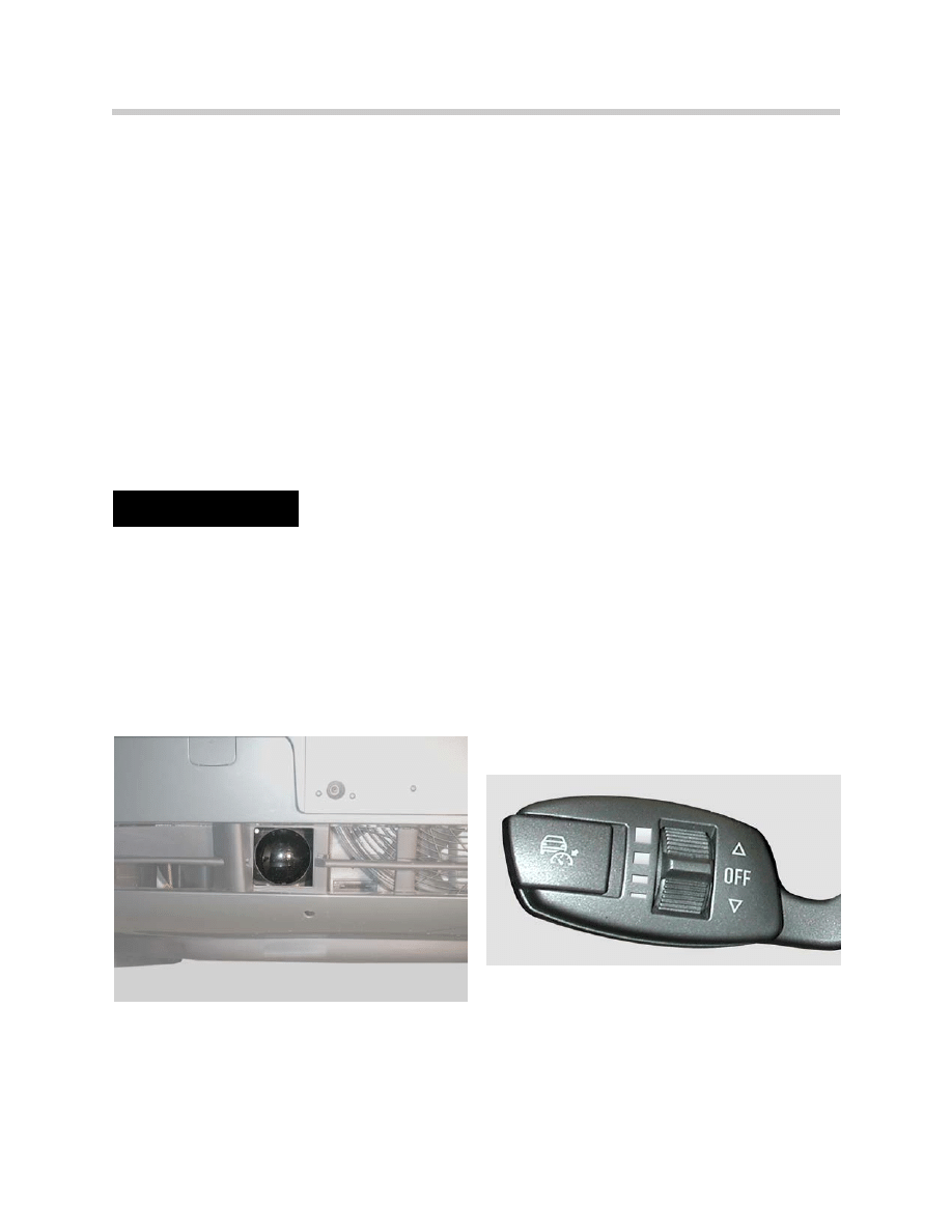
System Components
The ACC system consists of the following components:
• Sensor-Control Module Unit
• Steering Column Stalk Switch
• Instrument Cluster Display
3
E65 Active Cruise Control
Safety Notice!!!
Instrument Cluster Display
The instrument cluster display is responsible for visual indication of ACC operation.
Principle of Operation
ACC is a Comfort function and
NOT a Safety function.
The driver alone is responsible for the use of the ACC system including:
• Speed Selection
• Following Distance
• Acceptable weather conditions including visibility and road conditions
for cruise operation
4
E65 Active Cruise Control
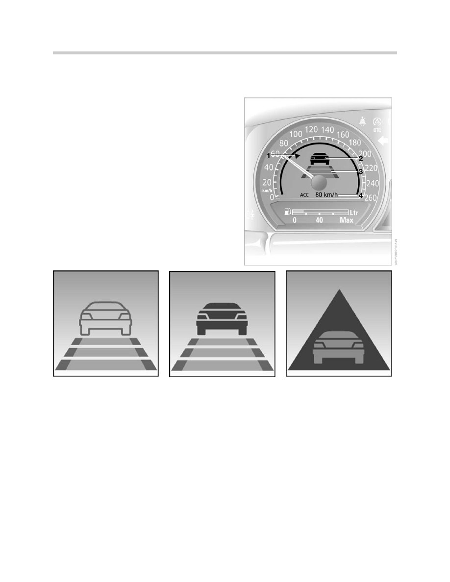
1. Indicator for stored desired speed
2. Indicator for detected vehicle
3. Indicator to show selected following distance
4. Digital speed display
Note: 1, 2 and 3 are shown when the system is
active. 4 is shown for a short time when
the desired speed in input.
Vehicle display is outlined:
System is active and no vehicle in
front is detected.
Vehicle display is solid:
System is active and vehicle is front is
detected.
Take over request:
Vehicle is display is in triangle and
flashes:
Driver should intervene by braking or
taking evasive action as required.
ACC cannot set following distance.
The system can be overridden at any time by the driver. Accelerating does not deactivate
the system. Braking results in system deactivation.
All stored information, speed and following distance, are reset with every key activation.
ACC is also reset in the case of non ACC requested DSC intervention.
The ACC system controls the following distance and cruise speed when the vehicle is
traveling between 20 mph and 110 mph.
Operation
If there is no object in front of the vehicle, the ACC system operates as a normal cruise
control. The desired speed input by the driver is regulated.
When an object is detected within the lane the ACC illuminates the object sensed indica-
tor. If the object being followed is traveling at a slower speed than is set by the cruise
control, the vehicle speed will be adapted (slowed) through either DME or DSC interven-
tion to maintain the requested follow distance (timed in seconds).
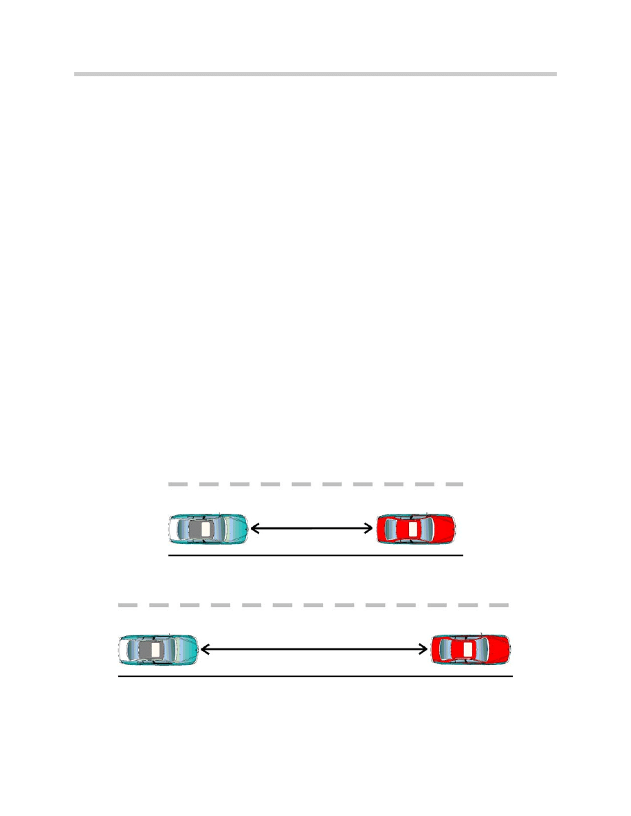
The distance to the lead object will vary with the time interval chosen by the driver and
vehicle speed. The speed of the vehicle will never exceed the preset cruise request of
the driver.
When the object is no longer in front of the vehicle, the preset speed request will be
resumed.
Note: The ACC will only detect moving objects. Objects that are stationary
(stopped) will be ignored.
5
E65 Active Cruise Control
1.8 Seconds
1.8 Seconds
35 MPH
55 MPH
Constant interval based on seconds, distance changes based on speed
To maintain proper follow distance the ACC system must be able to perform the following
tasks:
• Detect lead objects by radar sensing up to a distance of approx. 120m.
• Measure the distance, angle and relative speed of the lead object.
• Calculate in advance the presumed vehicle course.
• Select the relevant lead object for vehicle to object ranging.
• Adapt the actual vehicle speed to that of the lead object by:
Accelerating (Maximum acceleration rate 1.2 m/s2.
Decelerating (Maximum deceleration rate 2.0 m/s2.
• Monitor Lateral Acceleration (Maximum lateral acceleration 3.0 m/s2.
Deceleration
The ACC is only able to make limited relative speed corrections. The Maximum deceler-
ation rate is 2.0 m/s
2
(about 20% braking capacity). When the system has reached its
function limits, the driver is requested to intervene by the flashing indicator.
Side Visual Range
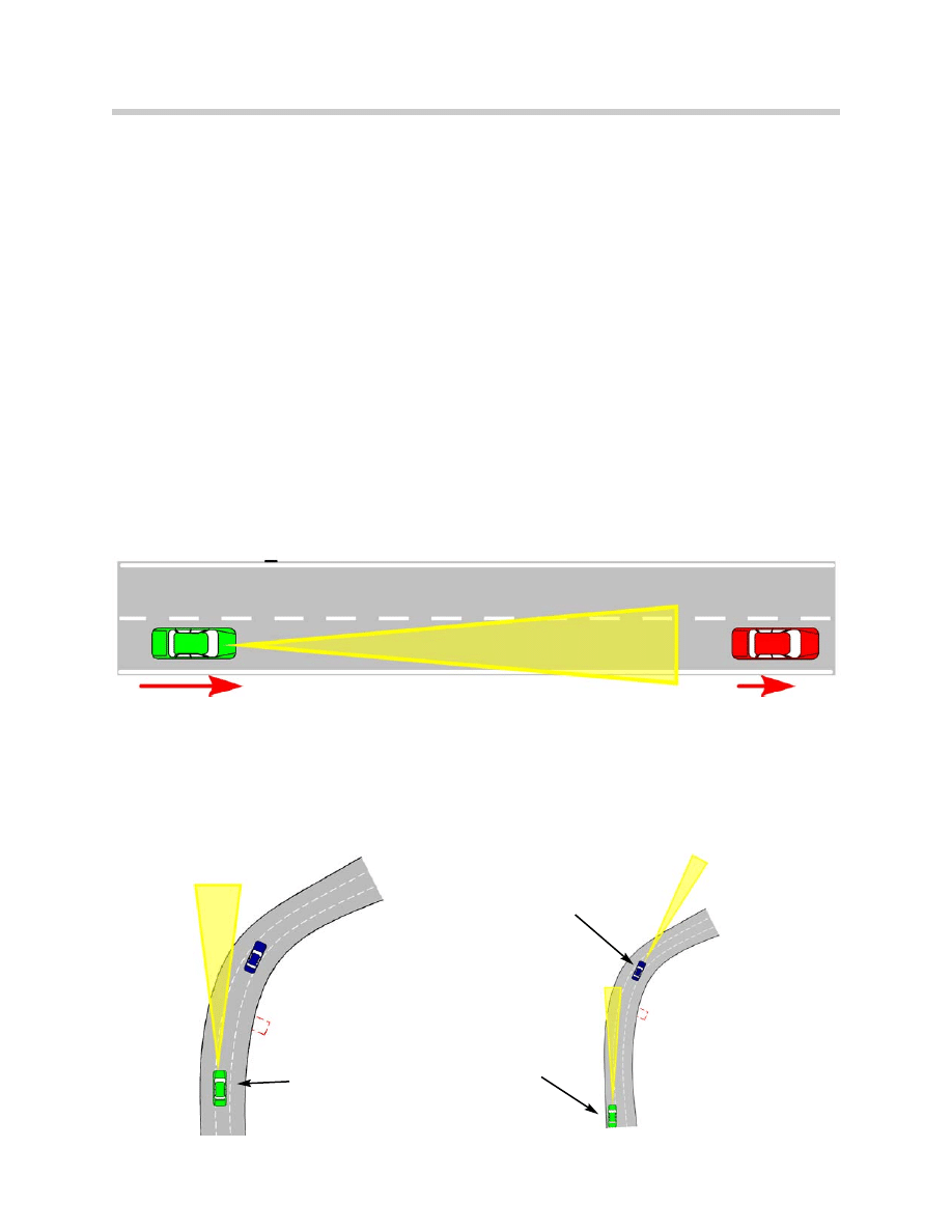
Because of the limited side visual range, the leading object may be lost around curves.
The ACC vehicle will not accelerate to the preset requested speed as long as the steer-
ing wheel is turned and curve recognition is active. After exiting the curve a time delay is
in effect to prevent rapid overtaking of the lead object.
6
E65 Active Cruise Control
This vehicle will not accelerate until the
time delay has expired
This vehicle will not accelerate
until the steering wheel is
straightened

Lane Prediction
In order to select the correct lead object for vehicle to vehicle ranging, the ACC must pre-
dict the future lane or path of the vehicle (ACC vehicle).
Lead objects are then relevant to a control operation when they are located in the actual
lane. Lane prediction is an advance calculation of the actual lane of travel.
The DSC unit provides vehicle speed and the Yaw sensor driving dynamics for the
advance calculation.
Limitations
The following limitations are in effect during ACC operation:
• Operation possible only between the speeds of 20 mph and 110 mph.
• Maximum deceleration rate 2.0 m/s2.
• Maximum acceleration rate 1.2 m/s2.
• Maximum transversal acceleration rate 3.0 m/s2.
ACC reaches its limitations in the following situations:
• The sensing range of the radar sensor limits the detection of objects that are
traveling in front in different lanes or around curves.
• An object cutting in results in delayed ACC responses. Do not use ACC on
winding roads or if frequent lane changes occur.
• High speed differences cannot be corrected.
• ACC cannot brake the vehicle to a complete standstill. The driver must assume
control of the vehicle by braking.
• ACC must only be used when visibility is adequate.
• If the time gap to the lead object is less than 1 second, especially in the case of the
lead object cutting in close to the front of the vehicle, ACC may not sense the lead
object in time for intervention, driver intervention is required.
7
E65 Active Cruise Control

Activation Conditions
The following preconditions must be met for ACC to become operational:
• Engine speed > 512 RPM
• No failure of Irreversible faults present in ACC
• ACC system “ON”
• Driving Speed > 20 MPH
• Park, Reverse or Neutral not engaged
• Parking brake not engaged
• DSC not active
Deactivation
The ACC is deactivated in several ways:
• Raising or lowering of the Stalk Switch
• Pressing the brake pedal
• Placing the transmission in Neutral
• Deactivating the DSC System
• Failure of one of the subsystems (Automatic Deactivation)
• Sensor Blindness (Automatic Deactivation)
• Vehicle speed drops below the minimum operating range (Automatic Deactivation)
• The DSC is active beyond a preset time threshold (Automatic Deactivation)
Lens Heater
The lens of the ACC sensor is heated to ensure better operation in winter and adverse
conditions. The heating coil is integrated into the plastic lens body.
Lens heating is temperature dependent as measured by an internal temperature sensor
in the ACC unit.
Despite the heater it is not possible to prevent sensor “Blindness” in all conditions.
Faults with the lens heating system are registered in the ACC unit fault memory.
8
E65 Active Cruise Control

Alignment
It is essential that the sensor be correctly aligned for proper system operation. Horizontal
mis-alignment will result in erroneous reaction to objects in a neighboring lane or a
delayed reaction to objects in the same lane.
ACC can compensate for minor horizontal misalignments up to 10, with slight function
impairments. In the event of more serious deviations, ACC will shut down and not be
available for operation.
The alignment procedure is only possible with the DISplus or the GT1 and the special
tools for ACC adjustment (PN 81-10-0-021-292). Also needed is 90 88 6 361 100 KDS
adapter.
Note: The tool is used in conjunction with other BMW special tools. Refer to
SIB B04 03 02. Always refer to the latest bulletins and repair instruc-
tions.
ACC sensor requires alignment if customer complaints are received regarding target
acquisition, an alignment error is stored in the fault code memory or the sensor has been
replaced.
Preconditions
Before the alignment procedure may be carried out, certain preconditions must be met.
• Guides Rails mounted to floor for mirror positioning.
• ACC is ONLY aligned with the BMW special tool package for ACC alignment.
• Vehicle must be proper distance from mirror,
• Vehicle chassis must be in proper alignment (Particularly in case of accident repair).
• Tire pressures must be set to proper specification.
• Ride height must be in nominal specs.
• ACC sensor must be clean.
• Guide Rails must be free of dirt.
• Battery charger must be connected to vehicle.
9
E65 Active Cruise Control

Workshop Hints
• Mark the floor for the vehicle positioning with lines for the front tire, both fore and aft
and side to side. This will save time and trouble.
• Floor rail should be mounted carefully with flat head screws not round head. Round
head screws interfere with the mirror unit.
• Slotted target is adjusted by the rear wheel with the slot adjusted to the height of the
wheel center (using the BMW cross-hairs).
• Make certain that the alignment holes in the BMW wheels are clean and free of
debris.
• If aftermarket wheels are mounted on the vehicle that do not have the alignment
holes, stock BMW wheels and tires must be mounted on the vehicle prior to ACC
alignment.
• All 4 wheels and tires must be factory spec sizes.
• All tires must be inflated to factory specs.
• Mount the wheel adapter securely and make sure it is straight.
• Any time the mirror unit is moved it must be leveled.
• The directions in the software refer to "front, middle and rear" mirror positions. This
refers to the top mirror adjustment, which tilts the mirror.
• Read the scales carefully. A mistake here will require a complete re-do.
• Only use DISplus or GT1 CD32 and newer. Older versions will not operate correctly.
• The track must be clean for the process, which allows the mirror unit to sit properly.
• Adjustment of the sensor requires a long handled T15 torx driver.
• Adjustment increments are in 0.1 of a turn. Small adjustments work best.
• Do not lean on the vehicle at any time during the process. This could alter the results
of the procedure.
• To start the test, select Service Functions, Active cruise control, Adjust ACC sensor
and Test Modules.
• When asked to enter values the return (enter) button must be pressed to accept the
value.
• Do not let the language of the text confuse you. The top scale is for the vertical axis
and the side scale is for the horizontal axis. The test may ask you to read off the top
scale, which "swivels about horizontal axis". Simply put this means that the vertical
axis is adjusted by swiveling about the horizontal axis.
10
E65 Active Cruise Control
• Adjustment of the ACC sensor is the last step of the procedure. It takes 3 or 4
"Loops" to adjust the sensor to a 0 reading on the vertical and horizontal axis. A
"Loop" is defined as one complete adjustment of both the vertical and horizontal
axis.
11
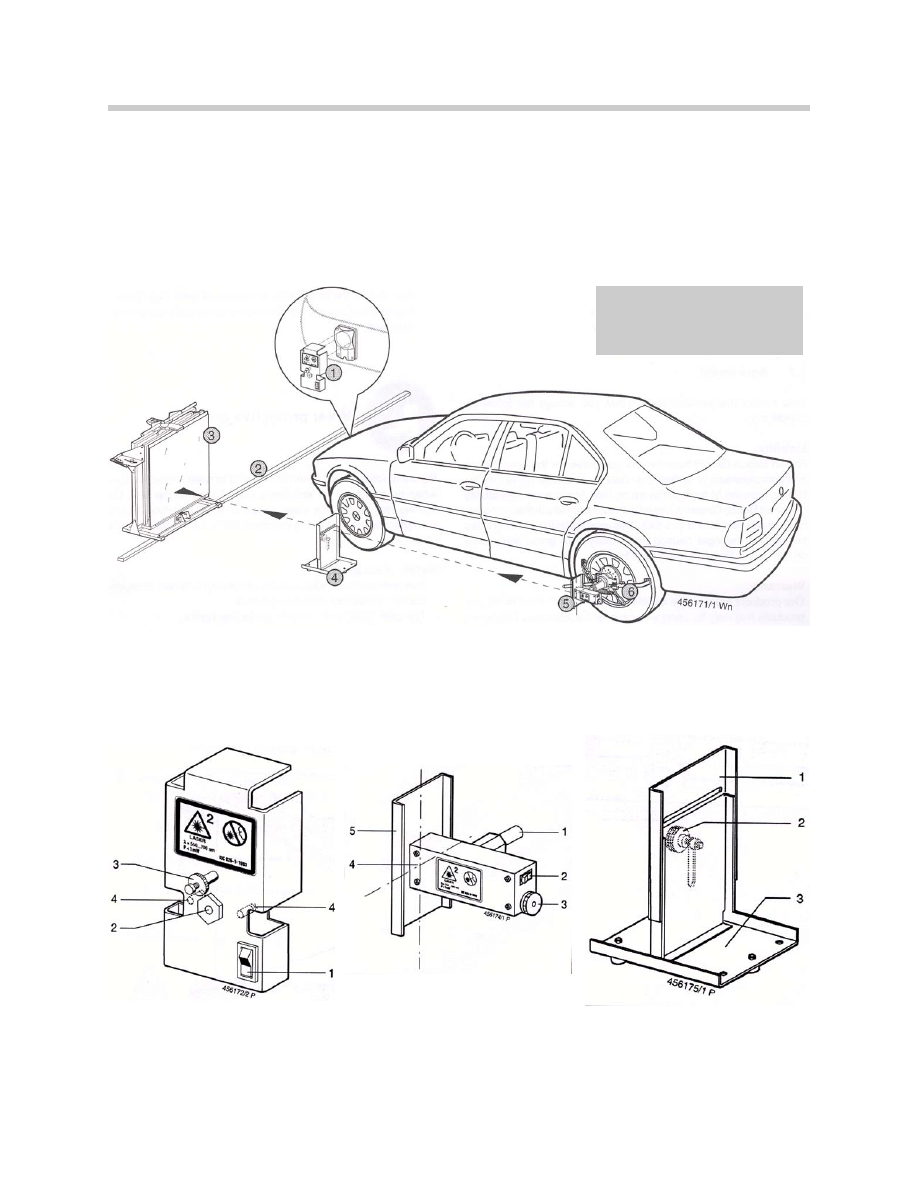
E65 Active Cruise Control
1. Coarse setting device
2. Rail
3. Mirror
4. Slotted cover
5. Wheel laser
6. KDS Clamp
Note:
The coarse setting tool is no
longer used for the coarse
adjustment
1. On/Off laser switch
2. Outlet aperture for laser
3. Locking screw
4. Screws for battery compartment
1. Axle for clamp
2. On/Off laser switch
3. Cover for battery
4. Outlet aperture for laser
5. Projection surface with crosshairs
1. Height adjustable slotted cover
2. Setscrew for cover
3. Baseplate
12
E65 Active Cruise Control
Workshop Exercise - ACC Alignment
Alignment Procedures
Note: The function of the ACC system depends greatly on the exact setting of
the ACC sensor. Meticulous care must be taken when carrying out the
setting according to the instructions provided in the Test Plan. The per-
missible tolerance in the horizontal and the vertical direction is 0.2
Degrees.
Once the procedure has begun DO NOT lean on the vehicle.
With the vehicle properly positioned in the service bay, measure the distance from the
mirror to the ACC sensor.
What is the specification for this distance?
Record the tire pressure specification and actual tire pressures below:
Adjust the laser and mirror as directed and begin making measurements.
Tire Pressure
Specification
Actual
Left Front
Right Front
Left Rear
Right Rear
Checklist Left Side of Vehicle
Mirror Level Set
Slot shutter set to
correct level
Measurement of slot
shutter level
Measured from?
Value on top scale
Value entered
Value on side scale
Value entered

Measuring Right Side of Vehicle
Adjusting the Mirror
13
E65 Active Cruise Control
Checklist Right Side of Vehicle
Mirror Level Set
Slot shutter set to
correct level
Measurement of slot
shutter level
Measured from?
Value on top scale
Value entered
Value on side scale
Value entered
Mirror Adjustment
Mirror in front of ACC sensor
Mirror leveled
Setting on top scale
Setting on side scale
Mirror position set properly
Adjustments required (vert)
Adjustments required (horiz)

Classroom Exercise - Review Questions
1.
How many following distances can be set with ACC?
2.
Why should ACC
NOT be used on roads with tight winding curves?
3.
What are some of the pre-conditions for ACC alignment?
4.
What special tools are need for ACC alignment?
5.
What are the maximum/minimum acceleration/deceleration rates?
14
E65 Active Cruise Control
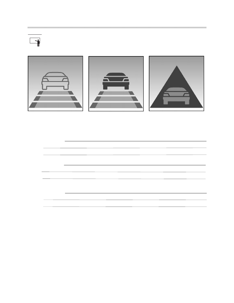
Classroom Exercise - Review Questions
6.
What do the above symbols indicate?
Symbol A:
Symbol B:
Symbol C:
15
E65 Active Cruise Control
Symbol A
Symbol B
Symbol C
Document Outline
- Main Menu
- Intro to Advanced Body Electronics
- E65 Power Module
- E65 Car Access System
- E65 Instrument Cluster
- E65 iDrive Driving Area
- E65 iDrive Comfort Area
- E65 Audio System
- E65 Navigation System
- E65 Telephone
- E65 Speech Processing System
- E65 Central Body Electronics
- E65 Remote Control Services
- E65 Automatic Trunk Lid Lift
- E65 Wiping Washing
- E65 Seat, Mirror, Steering Wheel
- E65 Lighting Systems
- E65 Driveaway Protection
- E65 Park Distance Control
- E65 Active Cruise Control
- Voltage Supply and Bus Systems
- 5 & 6 Series Body Electronics
- E60 Driver Information Systems
- E60 Communication Systems
- Car Communication Computer
- Head-Up Display
- Glossary
Wyszukiwarka
Podobne podstrony:
Cruise Control I4
82 Cruise Control
diagnostics Cruise Control
Cruise Control V6
2 5TD cruise control
32 Audi A6 Cruise control system petrol engines
Cruise Control Circuit
BMW E38 schematic Cruise control
04 6 F01 Cruise Control Systems
cruise control system
21 E65 Tire Pressure Control
diagnostics Cruise Control
22 E65 Park Distance Control
Opcom Cruise Control
CRUISE CONTROL SECTION 9U 19
07b E65 Park Distance Control
Toyota Avensis Y Corrolla esquema Cruise Control On Vehicle Inspection
więcej podobnych podstron