
Initial Print Date: 12/04
Table of Contents
Subject
Page
PDC Control Unit . . . . . . . . . . . . . . . . . . . . . . . . . . . . . . . . . . . . . . . . . . . . . . .4
Sensors . . . . . . . . . . . . . . . . . . . . . . . . . . . . . . . . . . . . . . . . . . . . . . . . . . . . . . .5
Activation of the PDC . . . . . . . . . . . . . . . . . . . . . . . . . . . . . . . . . . . . . . . . . . .8
PDC Acoustic Warning . . . . . . . . . . . . . . . . . . . . . . . . . . . . . . . . . . . . . . . . . .8
PDC Visual Warning . . . . . . . . . . . . . . . . . . . . . . . . . . . . . . . . . . . . . . . . . . . .9
Maximum visual detection range displayed in the CD . . . . . . . . . . . . .9
E65 Park Distance Control
Revision Date:

2
E65 Park Distance Control
E65 Park Distance Control (PDC)
Model: E65/E66
Production: All
After completion of this module you will be able to:
• Understand PDC operation
• Understand PDC sensor operation
• Locate and Identify PDC components
Introduction
The first PDC was introduced by BMW in the U.S. for the E38 in 1995. The PDC of the
E65 is a further development of the E38 PDC.
PDC assists the driver when maneuvering into and out of parking spaces. The signal
tones and a visual display indicate the current distance to an obstacle.
The new features of the PDC are:
• Acoustic distance warning using the audio system speakers
• Visible distance indicator in the Control Display (CD)
• Check Control messages in the Kombi and CD
System Overview
3
E65 Park Distance Control
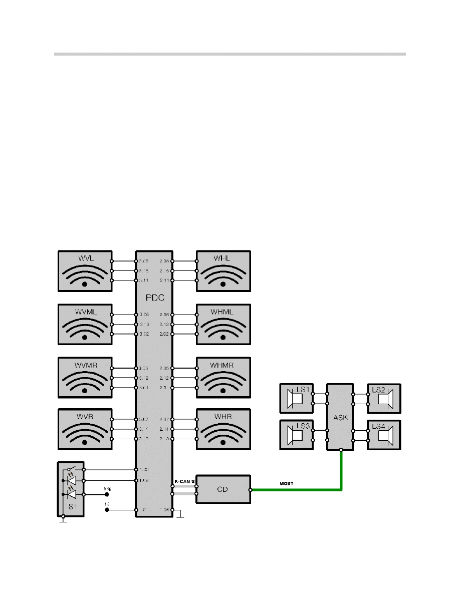
Components
PDC Control Unit
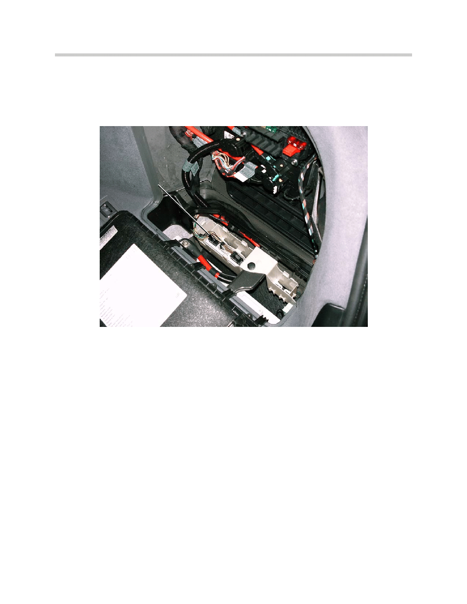
The PDC Control Unit is located in the right rear corner of the luggage compartment.
Its main tasks are:
• Activation of sensors and reception of echo signals.
• Evaluation of the received echo signals.
• Activation of the function indicator (LED in the switch).
• Sending messages via K-CAN-S to ASK and the CD.
• Monitoring the inputs and outputs.
• Management of the diagnosis and test functions.
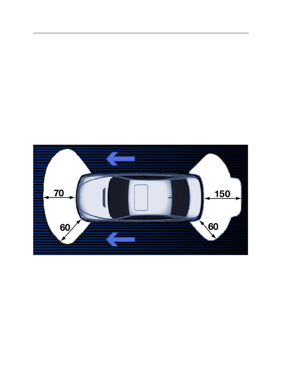
PDC uses the echo sounding principle to calculate the distances between each of the
4 sensors in the front and rear bumpers and any obstacle that might be present.
In addition, a three-way calculation can be used to calculate the effective distance to
the bumper in the case of an obstacle between two sensors.
This three-way calculation is enabled by co-sensing of the neighboring sensors.
An active sensor system in the converter processes the received echo signals, performs
the evaluation and communicates across a bi-directional data line with the control unit.
4
E65 Park Distance Control
PDC Control Unit
Sensors
The PDC system of the E65 uses 8 sensors in total, 4 in the front bumper and 4 in the
rear.
The control unit sends a digital signal to set the ultrasonic sensor either in a combined
transmit and receive mode or in a receive only mode.
Combined Mode
The sensor first transmits a packet of ultrasonic impulses and then receives the echoes
reflected by the obstacle within its sensing range.
On the basis of the time span between transmission and reception, the control unit calcu-
lates the distance to the obstacle.
Receive Only Mode
The sensor receives the impulses deflected by the neighboring sensors. The evaluation
of these signals in the control unit improves the certainty of detection of the system.
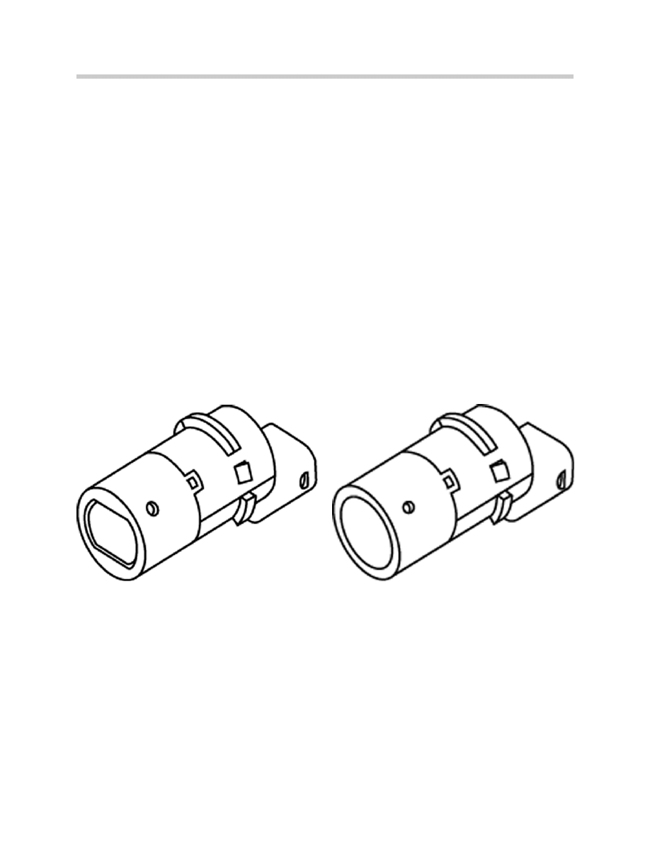
The design of the sensor varies from that used until now in that the outer membranes are
completely round instead of oval.
The advantages of this new round membrane shape are the greater detection range and
lower sensitivity in wet conditions. The sensors are always painted in body color.
5
E65 Park Distance Control
Previous Sensor
(E38, E39 etc.)
E65 PDC Sensor
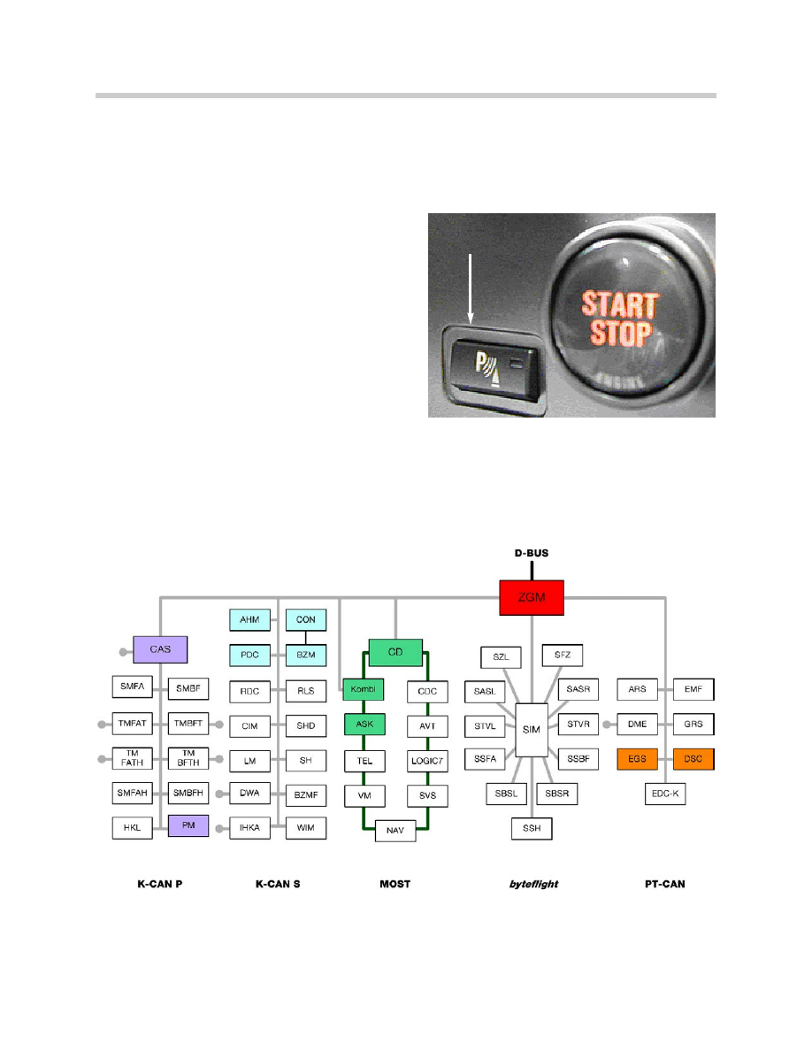
PDC Button
The PDC button is to the left of the start/stop button and it consists of the following
components:
• Button
• Function indicator (LED)
• Location light
The button can be used to activate or deacti-
vate PDC manually. The locating light is con-
nected to terminal 58g. The function indica-
tor LED is connected to the control unit.
When the PDC is activated, the LED turns on
permanently. In the event of an error mes-
sage, it flashes at a frequency of 2 Hz.
Interfaces
The communication with the vehicle electronics takes place across the K-CAN S.
6
E65 Park Distance Control
PDC Button

Audio System Controller (ASK)
The acoustic distance warning is output through the front midrange speaker of the audio
system in the doors and in the rear shelf. The signal tones for all 4 loudspeakers as well
as their intervals are processed in the ASK and mixed with the current audio output.
The dedicated speakers used until now are no longer used in the E65.
Control Display (CD)
If the “PDC Pic” option is enabled from the “Settings” menu, the visual distance warning
is displayed in the CD and the graphic is generated in the CD.
Instrument Cluster
The instrument cluster is used by the PDC as a display unit for Check Control (CC) mes-
sages. The PDC control unit also receives the outside temperature as well as the
mileage reading from the instrument cluster.
Ice and dew can lead to false activations of the ultrasonic sensors. In order to reduce the
effect of this phenomenon, the response characteristics are adapted via software as of
+6ºC and colder.
In the case of a fault code entry in the fault memory, the km reading and the outside tem-
perature are also stored.
Dynamic Stability Control DSC
The DSC control unit provides the speed signal.
Adaptive Gearbox Control (AGS)
The AGS provides the reverse gear signal for automatic activation of the PDC.
CAR Access System (CAS)
The CAS reports the terminal status (KLR, KL15, KL50).
Power Module (PM)
The PM telegrams the vehicle battery voltage.
7
E65 Park Distance Control
Principle of Operation
Activation of the PDC
The system is activated automatically with a delay of approximately one second when the
ignition is on and the selector lever is moved reverse.
After a driving distance of 50 m or a speed of 30 km/h is exceeded, the system switches
off. The indicator LED in the button goes out when the system is no longer active.
The PDC can also be manually activated or deactivated by using the PDC button.
PDC Acoustic Warning
The distance to an obstacle is indicated by an intermittent tone according to its distance
from the sensor. If, for example, an obstacle is detected to the left front of the vehicle, the
sound signal is issued at the left front speaker.
The closer the vehicle comes to the object, the shorter the frequency of the signal
becomes. If the distance to a detected object is smaller than approximately 30 cm
(11 in.), a continuous tone is issued.
The sound signal is interrupted after approximately 3 seconds if the vehicle is driven
parallel to a wall.
This interruption does not occur in the continuous tone mode (distance smaller than
30 cm).
8
E65 Park Distance Control
PDC Visual Warning
The distance to an obstacle can also be displayed visually in the Control Display.
To enable the visual display Select “settings” in the CD and then select the “other vehicle
functions” page which is displayed as the silhouette of a car. Activate it by pressing
“PDC pic.”
Once the visual display is enabled it will always display whenever the PDC becomes
active.
The display takes priority over any item that is currently being displayed on the Control
Display. It can be temporarily switched off by pressing down on the Controller.
To disable the visual display completely requires returning to the settings menu and
de-selecting it.
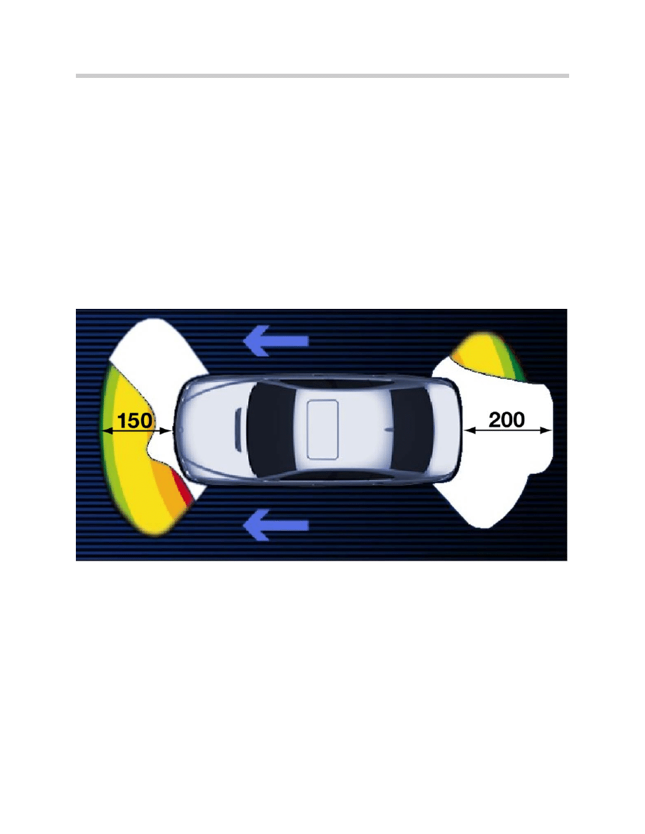
Maximum visual detection range displayed in the CD
The visual display uses color to distinguish how close an object is, the following
colors are used:
• Green: over 100 cm (39 inches)
• Yellow: 100 to 50 cm (38 to 19 inches)
• Red: less than 50 cm (less than 19 inches)
9
E65 Park Distance Control
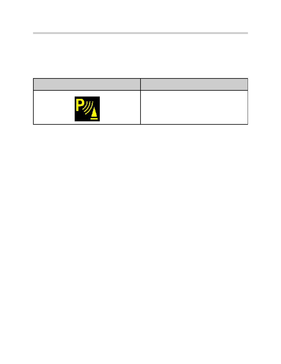
Check Control Message
If there is a fault in the PDC system, no acoustic and visual warning is issued. The LED
indicator in the PDC button flashes.
The following Check Control Message is issued:
Diagnosis
The following system components are monitored and stored as faults in the non-volatile
fault code memory.
• Sensors
• Data line to the sensors
• Voltage supply for sensors
• Button
• Function indicator LED of the button
• Control Unit
• K-CAN S
In addition to the type of fault, the following environmental conditions are also stored:
• Frequency
• Kilometer reading
• Outside temperature
10
E65 Park Distance Control
Check Control message displayed in KOMBI
Message displayed in Control Display
PDC Failure!
“PDC failure!” No acoustic warning available for PDC.
Please contact your BMW center as soon as possible.

Classroom Exercise - Review Questions
1.
What control unit is responsible for generating the acoustic output of the PDC?
How does it receive the request?
2.
How is the visual display of the PDC enabled? Does it have to be turned on this
way every time the driver wishes to have the visual display?
3.
What is the difference between the PDC sensors on the E65 as compared to the
E38?
4.
Where is the PDC module located?
11
E65 Park Distance Control
Document Outline
- Main Menu
- Intro to Advanced Body Electronics
- E65 Power Module
- E65 Car Access System
- E65 Instrument Cluster
- E65 iDrive Driving Area
- E65 iDrive Comfort Area
- E65 Audio System
- E65 Navigation System
- E65 Telephone
- E65 Speech Processing System
- E65 Central Body Electronics
- E65 Remote Control Services
- E65 Automatic Trunk Lid Lift
- E65 Wiping Washing
- E65 Seat, Mirror, Steering Wheel
- E65 Lighting Systems
- E65 Driveaway Protection
- E65 Park Distance Control
- E65 Active Cruise Control
- Voltage Supply and Bus Systems
- 5 & 6 Series Body Electronics
- E60 Driver Information Systems
- E60 Communication Systems
- Car Communication Computer
- Head-Up Display
- Glossary
Wyszukiwarka
Podobne podstrony:
22 E65 Park Distance Control
05c1 E70 Park Distance Control
21 E65 Tire Pressure Control
07c E65 Active Cruise Control
15 E65 Remote Control Service
05b E65 Remote Control Services
Kim Control of auditory distance perception based on the auditory parallax model
Park Narodowy Salonga
Damage Control Plan
Slowinski Park Narodowy (prezentacja)
Drawieński Park Narodowy(1)
Gorczański Park Narodowy (prezentacja)
Biebrzaski Park Narodowy
Park Narodowy Gór Stołowych (prezentacja)
14 Controllingid 15298 ppt
Controlling w przedsiębiorstwie
overview simatic controllers 04 2007 en plc
więcej podobnych podstron