
Initial Print Date: 10/06
Table of Contents
Subject
Page
Park Distance Control . . . . . . . . . . . . . . . . . . . . . . . . . . . . . . . . . . . . . . . . . . .4
Input/Output - Park Distance Control . . . . . . . . . . . . . . . . . . . . . . . . . . . . . .5
System Circuit Diagram - Park Distance Control . . . . . . . . . . . . . . . . . . . .6
Functional Principle of the Ultrasonic Sensors . . . . . . . . . . . . . . . . . . . . . .8
Send Mode . . . . . . . . . . . . . . . . . . . . . . . . . . . . . . . . . . . . . . . . . . . . . . . . . . . .8
Receive Mode . . . . . . . . . . . . . . . . . . . . . . . . . . . . . . . . . . . . . . . . . . . . . . . . . .9
Function Activation . . . . . . . . . . . . . . . . . . . . . . . . . . . . . . . . . . . . . . . . . . . . .9
Automatic Activation . . . . . . . . . . . . . . . . . . . . . . . . . . . . . . . . . . . . . . . . . . . .9
Automatic Deactivation . . . . . . . . . . . . . . . . . . . . . . . . . . . . . . . . . . . . . . . . . .9
Manual Activation . . . . . . . . . . . . . . . . . . . . . . . . . . . . . . . . . . . . . . . . . . . . .10
Distance Signalling . . . . . . . . . . . . . . . . . . . . . . . . . . . . . . . . . . . . . . . . . . . .10
Audible Distance Signalling . . . . . . . . . . . . . . . . . . . . . . . . . . . . . . . . . . . . .10
Visual Distance Signalling . . . . . . . . . . . . . . . . . . . . . . . . . . . . . . . . . . . . . .12
Trailer Mode . . . . . . . . . . . . . . . . . . . . . . . . . . . . . . . . . . . . . . . . . . . . . . . . . .13
Rear-view Camera . . . . . . . . . . . . . . . . . . . . . . . . . . . . . . . . . . . . . . . . . . . . .13
Park Distance Control with Eight Channels . . . . . . . . . . . . . . . . . . . . . . .16
Park Distance Control Functions . . . . . . . . . . . . . . . . . . . . . . . . . . . . . . . .17
Diagnosis . . . . . . . . . . . . . . . . . . . . . . . . . . . . . . . . . . . . . . . . . . . . . . . . . . . . .18
System Limits . . . . . . . . . . . . . . . . . . . . . . . . . . . . . . . . . . . . . . . . . . . . . . . . .18
Cleaning the Ultrasonic Sensors . . . . . . . . . . . . . . . . . . . . . . . . . . . . . . . .19
System Error . . . . . . . . . . . . . . . . . . . . . . . . . . . . . . . . . . . . . . . . . . . . . . . . . .19
E70 Park Distance Control (PDC)
Revision Date:

Subject
Page
BLANK
PAGE

3
E70 Park Distance Control
Park Distance Control
Model: E70
Production: From Start of Production
After completion of this module you will be able to:
• Describe the operation of the Park Distance Control on the E70.
• Diagnose the PDC on the E70.
4
E70 Park Distance Control
Park Distance Control
The Park Distance Control (PDC) is a distance warning system that provides both visual
and audible information on the distance to the nearest obstacle when parking and driving
out of spaces.
The park distance control is optionally available in the E70.
The distance to the next obstacle is measured by means of four ultrasonic sensors in the
rear bumper and four ultrasonic sensors in the front bumper. The distance is signalled
audibly via the speakers in the rear and front area of the vehicle. The frequency of the
signal increases as the distance to the obstacle decreases.
A continuous signal is output in very close proximity to obstacles (about 30 cm).
The distance signalling is shown in graphic form on the central information display CID.
The park distance control can be switched on and off by means of a button in the center
console switch cluster SZM.
The following changes/new features have been implemented compared to the
predecessor models:
• New converter and new control unit
• Visual representation of distance to obstacle
• Audible signalling through radio speakers
Introduction
5
E70 Park Distance Control
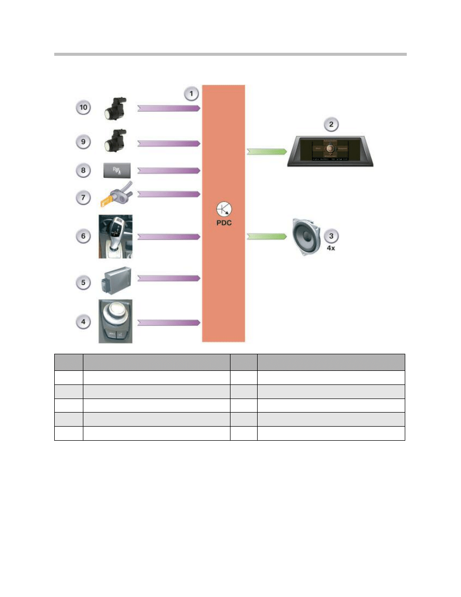
Input/Output - Park Distance Control
With the aid of the controller (4), representation of the park distance control (1) can be set
on the central information display (2). The trailer module (5) informs the park distance
control whether a trailer is hitched to the vehicle in order to deactivate the rear transduc-
ers (9). Park distance control is activated on engaging reverse gear with the gear selector
lever (6). The park distance control can be switched on/off with the button (8).
Corresponding to the setting of the park distance control system, the driver can be
informed both acoustically (3) and visually (2) of the distance to the nearest obstacle while
parking/ maneuvering . The audible information is always available when the park distance
control is activated.
Index
Explanation
Index
Explanation
1
Park distance control
6
Gear selector lever
2
Central information display CID
7
Wheel speed sensor
3
Speaker
8
Park distance control button
4
Controller
9
Rear transducer (ultrasonic sensor)
5
Trailer module
10
Front transducer (ultrasonic sensor)
6
E70 Park Distance Control
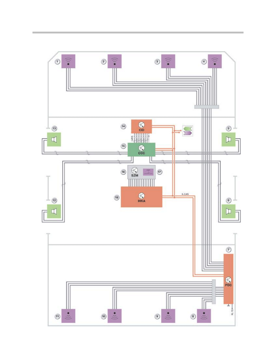
System Circuit Diagram - Park Distance Control
7
E70 Park Distance Control
Index
Explanation
Index
Explanation
1
Front left transducer (ultrasonic
sensor)
12
Speaker, rear driver's side
2
Front center left transducer
13
Speaker, front driver's side
3
Front center left transducer
14
Central information display CID
4
Front right transducer
15
Car communication computer*
5
Speaker, front passenger's side
16
Center console switch cluster
6
Speaker, rear passenger's side
17
PDC button
7
Park distance control PDC
18
Integrated automatic climate control
IHKA
8
Rear right transducer
K-CAN
Body CAN
9
Rear center right transducer
KL15
Terminal 15
10
Rear center left transducer
LVDS
Low voltage differential signal
11
Rear left transducer
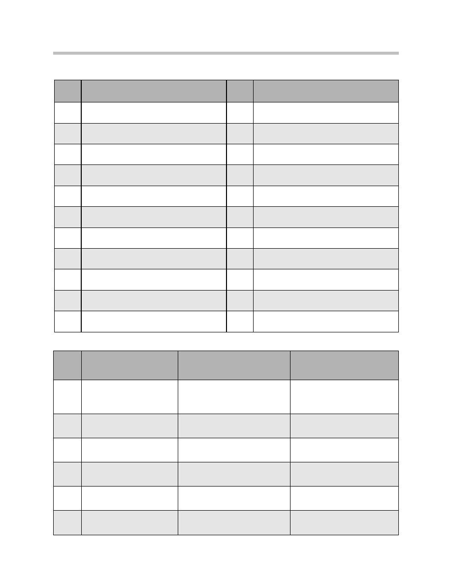
In/Out
Information
Source
Function
In
Vehicle speed
signal
Rotation rate sensor >dynamic
stability control >junction-box
ECU>instrument cluster
Deactivation of park distance
control as from 12mph/20 km/h
In
Distance signal
Rotation rate sensor > dynamic
stability control > junction-box
ECU> instrument cluster
Deactivation of park distance
control after distance of 50 m
In
Outside
temperature
Outside temperature
sensor > instrument cluster
Temperature is one of the refer-
ence variables for calculating dis-
tance
In
Trailer
Trailer socket towing hitch
> trailer module
Rear park distance control deac-
tivated when trailer is connected
In
Reverse gear
status
Gear selector lever > electronic
transmission control
Park distance control ON, with
reverse gear engaged
Out
Check control message
Park distance control
Display of CC message
K-CAN Signals at Park Distance Control
Legend for System Circuit Diagram - Park Distance Control
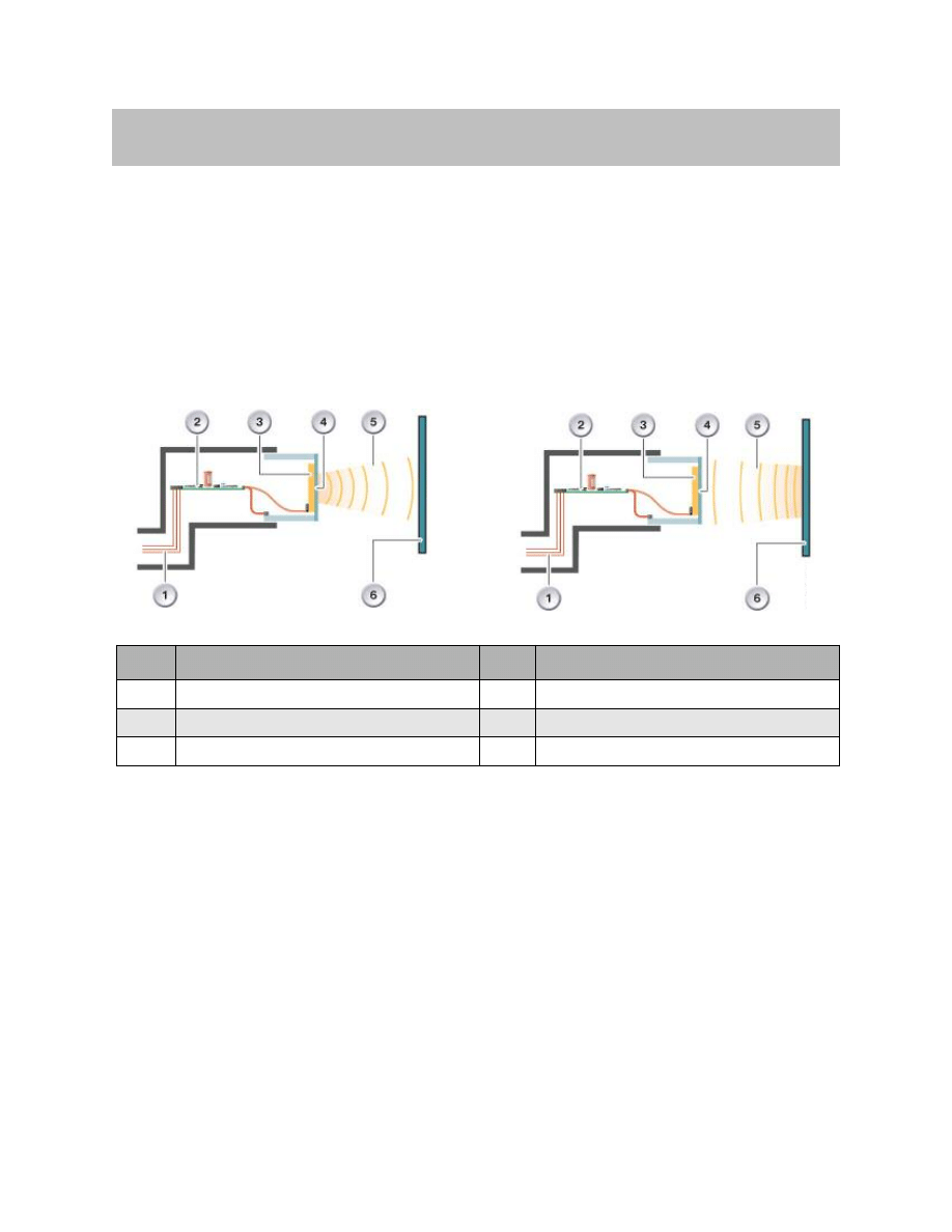
Functional Principle of the Ultrasonic Sensors
Operation of the ultrasonic sensors is based on the echo-sounding principle.
Short ultrasonic pulses are sent out by the ultrasonic sensor, reflected from objects in the
vicinity and received again by the ultrasonic sensor.
The ultrasonic sensor sends the period of time required between sending the ultrasonic
pulse and receiving the first echo to the park distance control module which, in turn, cal-
culates the distance to the nearest object from this period of time.
Send Mode
The ultrasonic sensor behaves as a "speaker" in send mode.
At about 40 kHz to 50 kHz, the selected ultrasonic frequency is outside the range in
which people, pets and domestic animals are not adversely affected.
The electronics of the ultrasonic sensor produces electrical pulses to set the Piezo-
ceramic element in motion (conversion of electrical energy to mechanical energy).
The Piezo-ceramic element is located on the inside of the outer diaphragm. The outer
diaphragm vibrates in line with the resonance frequency and produces ultrasonic waves.
The short pulse sequences hit an obstacle and are bounced back (reflected).
8
E70 Park Distance Control
Functions
Index
Explanation
Index
Explanation
1
Ultrasonic sensor connection
4
Outer diaphragm
2
Ultrasonic sensor electronics
5
Ultrasonic waves
3
Piezo-ceramic element
6
Obstacle/wall

Receive Mode
The ultrasonic sensor behaves as a "microphone" in receive mode.
After the outer diaphragm has settled (about 1 ms), the ultrasonic sensor receives the
ultrasonic waves reflected by the obstacle. Vibrations are induced in the outer diaphragm
and Piezo-ceramic element which transfer the electrical pulses to the electronic ultrason-
ic sensor module.
The electrical measured signal is digitized and sent to the park distance control. The data
are processed in the park distance control module and the distance to the obstacle cal-
culated.
The echo propagation time is calculated from the start time of sending the signal and
from the time of the incoming echo. Based on the known ultrasonic speed in air, the echo
propagation time is a measure for the distance to the obstacle.
Function Activation
The park distance control performs a system test after switching on the ignition. The park
distance control is ready for operation after the system test has been successfully com-
pleted. Any system faults are indicated in the form of check control messages in the
instrument cluster and central information display.
Automatic Activation
The park distance control is activated automatically by engaging reverse gear. Activation
takes place with a delay of about 1 second. This delay prevents unintentional activation of
the park distance control when passing through the R-position when changing the drive
range.
On vehicles equipped with a central information display, it is possible to select whether
the distance to the obstacle is to be indicated visually.
Automatic Deactivation
The front and rear park distance control remains active after disengaging reverse gear.
Automatic deactivation of the park distance control is initiated under following conditions:
• Vehicle speed greater than 12 mph/20 kmh
• Distance greater than 50 m
9
E70 Park Distance Control
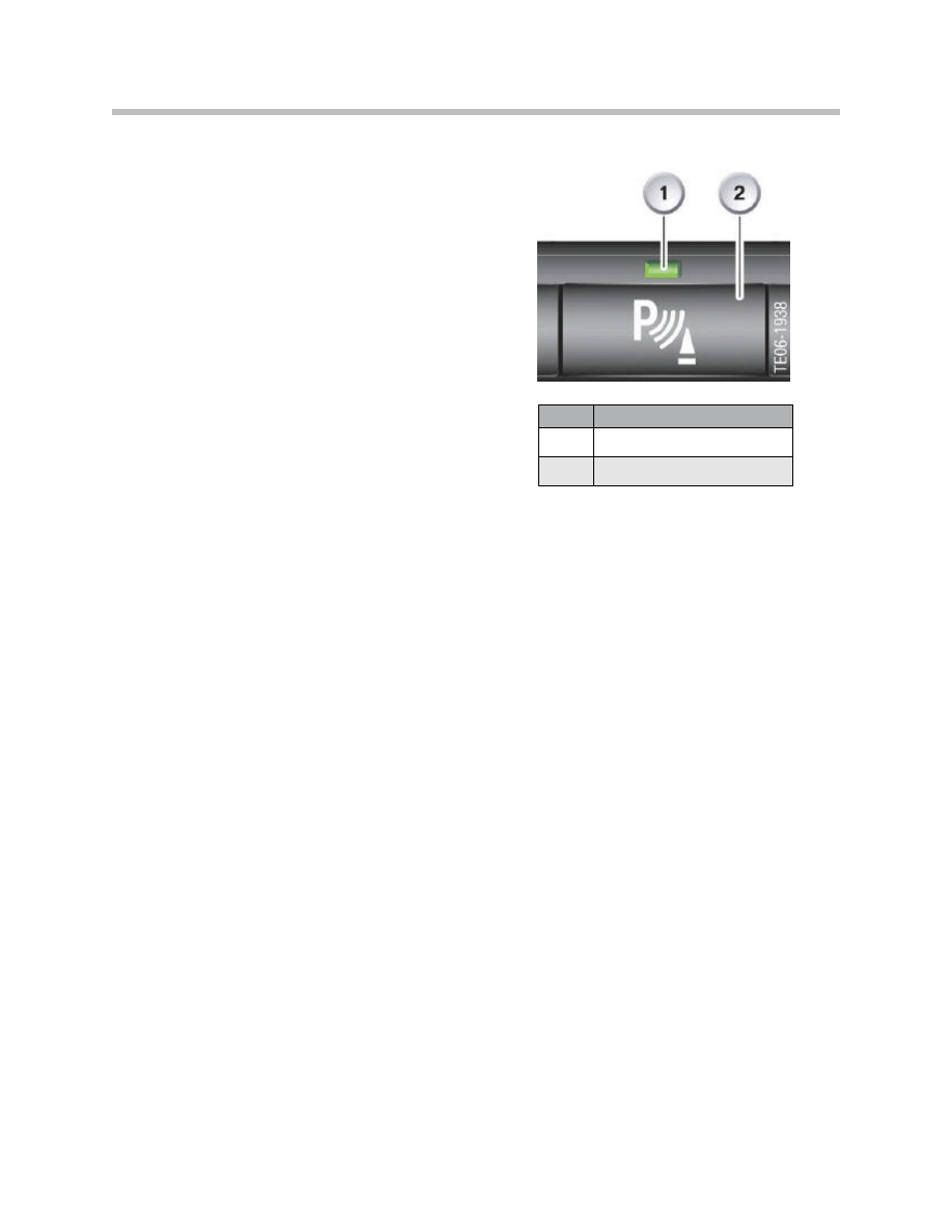
Manual Activation
The park distance control can be switched on
or off by pressing the PDC button (2).
Illumination of the function indicator (1) in the
PDC button indicates that the park distance
control and therefore the distance recognition
function is active.
Manual activation of the function is possible
only up to a road speed of about
12 mph / 20 kmh.
Note: The signal from the PDC button is evaluated by the integrated automatic
climate control. The integrated automatic climate control sends the sig-
nal via the K-CAN to the park distance control.
Distance Signalling
The distance between the vehicle and an obstacle is always signalled audibly. The repre-
sentation can be additionally activated on the central information display showing a
schematic representation of the vehicle and the obstacles.
Audible Distance Signalling
Corresponding to the vehicle equipment, the distance is signalled audibly through the
speakers of the audio system.
The signal frequency changes corresponding to the distance of the vehicle to the obsta-
cle. The shorter the distance of the vehicle from the obstacle the faster the tone
sequence. A continuous tone is output at a distance below about 30 cm.
As the vehicle moves away from the obstacle, the audible signal is immediately switched
off as soon as the distance changes by more than 10 cm. This tolerance range is neces-
sary to ensure that small changes in distance (<10 cm) do not result in deactivation of the
audible signal.
10
E70 Park Distance Control
Index
Explanation
1
Function indicator
2
PDC button

To avoid irritating the driver, the signal tone of the park distance control (outer ultrasonic
sensor(s)) is switched off after about 3 seconds when driving very close to and along
a wall. The prerequisite is that the distance is outside the continuous tone range
(> 30 cm). The audible signal is sounded again on approaching this range.
Front Detection Range
The detection range for the audible warning at the front is:
• Left/right about 60cm
• Center about 70cm
Rear Detection Range
The detection range for the audible warning at the rear is:
• Left/right about 60cm
• Center about 150cm
Audio System
The audio system (car communication computer) receives the signals via the K-CAN
from the park distance control for the purpose of audible distance signalling. The audio
system processes the signals, after which the audible signal for the speakers is generat-
ed. Parallel to this, the distance is shown visually on the central information display.
Note: Signal processing takes place in the CHAMP if no car communication
computer is installed.
In order to better locate small obstacles as well as obstacles located only on one side of
the vehicle, only the speaker installed on the corresponding side of the vehicle is activat-
ed when the obstacle is detected by an outer ultrasonic sensor.
This function to distinguish between left and right can be disabled by way of coding. The
obstacle closest to the vehicle is indicated. The mid-range speakers on the left and right
are activated as soon as a centrally positioned ultrasonic sensor detects an object.
The audible signal is not output simultaneously at the front and rear. If the distance of the
obstacles to the front and rear of the vehicle is below about 30cm, the audible signal is
output alternately at the front and rear at 1 second intervals.
11
E70 Park Distance Control
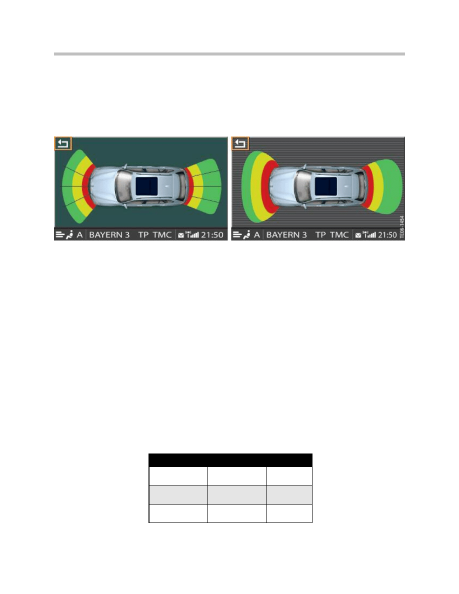
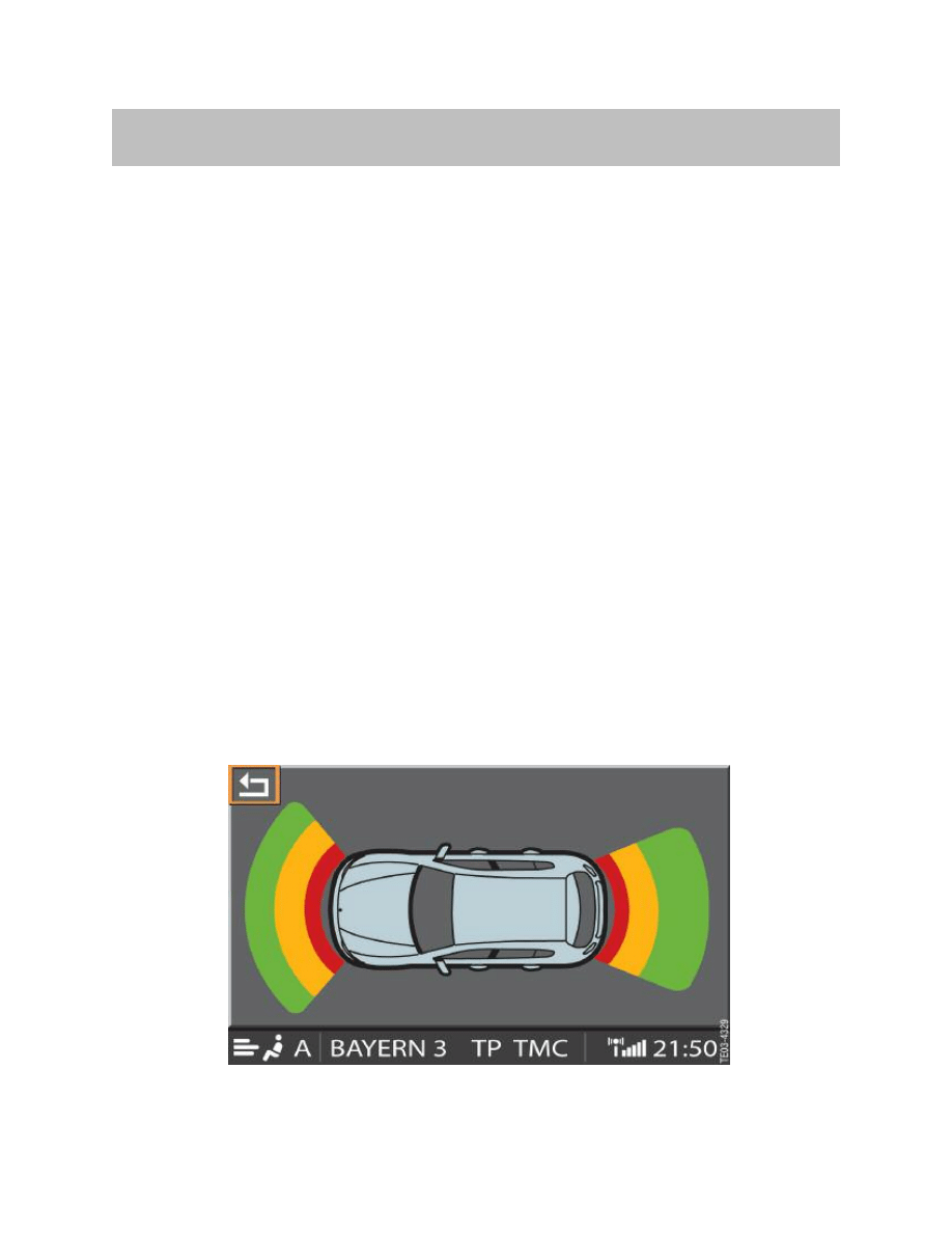
Visual Distance Signalling
In the E70, the distance to an obstacle can also be indicated visually. The visual display
can be permanently switched on or off by means of the controller for the central informa-
tion display. The audible indication always remains active.
The park distance control is shown in the central information display when visual distance
signalling and park distance control have been activated.
The visual distance signalling indicates obstacles earlier than the audible signalling. The
acquisition range is up to 250 cm. The vehicle and the obstacles are shown in a top view.
The grey background represents the monitored area. The obstacles in this area are
shown in green, yellow and red corresponding to the distance from the vehicle.
The audio system receives the distance information between the ultrasonic sensors and
the obstacle from the park distance control via K-CAN and generates the corresponding
graphic representation.
The central information display outputs the information and superimposes this represen-
tation on the central information display.
The previous display is shown automatically in the central information display when the
park distance control is switched off. The display ranges at the front/rear are identical and
shown in the following table.
12
E70 Park Distance Control
Color
Outside
Inside
Green
>100
>100
Yellow
50 to100
50 to100
Red
<50
<50
Distance from obstacle in cm

Trailer Mode
When pulling a trailer, the trailer module informs the park distance control via the K-CAN
that a trailer is hitched to the vehicle. The park distance control deactivates the ultrasonic
sensors for the rear area of the vehicle.
Note: The park distance control receives the information that the trailer is
hitched to the vehicle only when the trailer lighting is connected.
Rear-view Camera
The rear-view camera can be combined with the data made available by the park distance
control. For instance, obstacles detected by the park distance control can be shown in
the real image of the rear-view camera.
The image is shown on the central information display. The image of the rear-view cam-
era is optional and can be switched over to the central information display. This function
can be set by means of the controller. The audible park distance control remains active.
More detailed information on changeover functions and possible representations can be
found in the Product Information "Rear-view camera E70".
13
E70 Park Distance Control
Ultrasonic Sensors
The ultrasonic sensors fitted in the E70 offer new product advantages such as greater
range and optimized design.
Greater Range
The range of the new ultrasonic sensors is about 250 cm. The entire range of the ultra-
sonic sensors is used for visual distance signalling. The ultrasonic sensors are reduced
to a range of minimum 150 cm for acoustic distance signalling.
Optimized Design
The new ultrasonic sensors are about 50% shorter than the previous ultrasonic sensor
and have a smaller diaphragm (important for design). The smaller diaphragm has been
made possible by new design methods.
The diaphragm is no longer decoupled from the bumper trim in the ultrasonic sensor
itself but rather it is now decoupled by means of a de-coupling ring.
14
E70 Park Distance Control
System Components
Index
Explanation
1
Junction-box ECU
2
Park distance control
3
Central information display
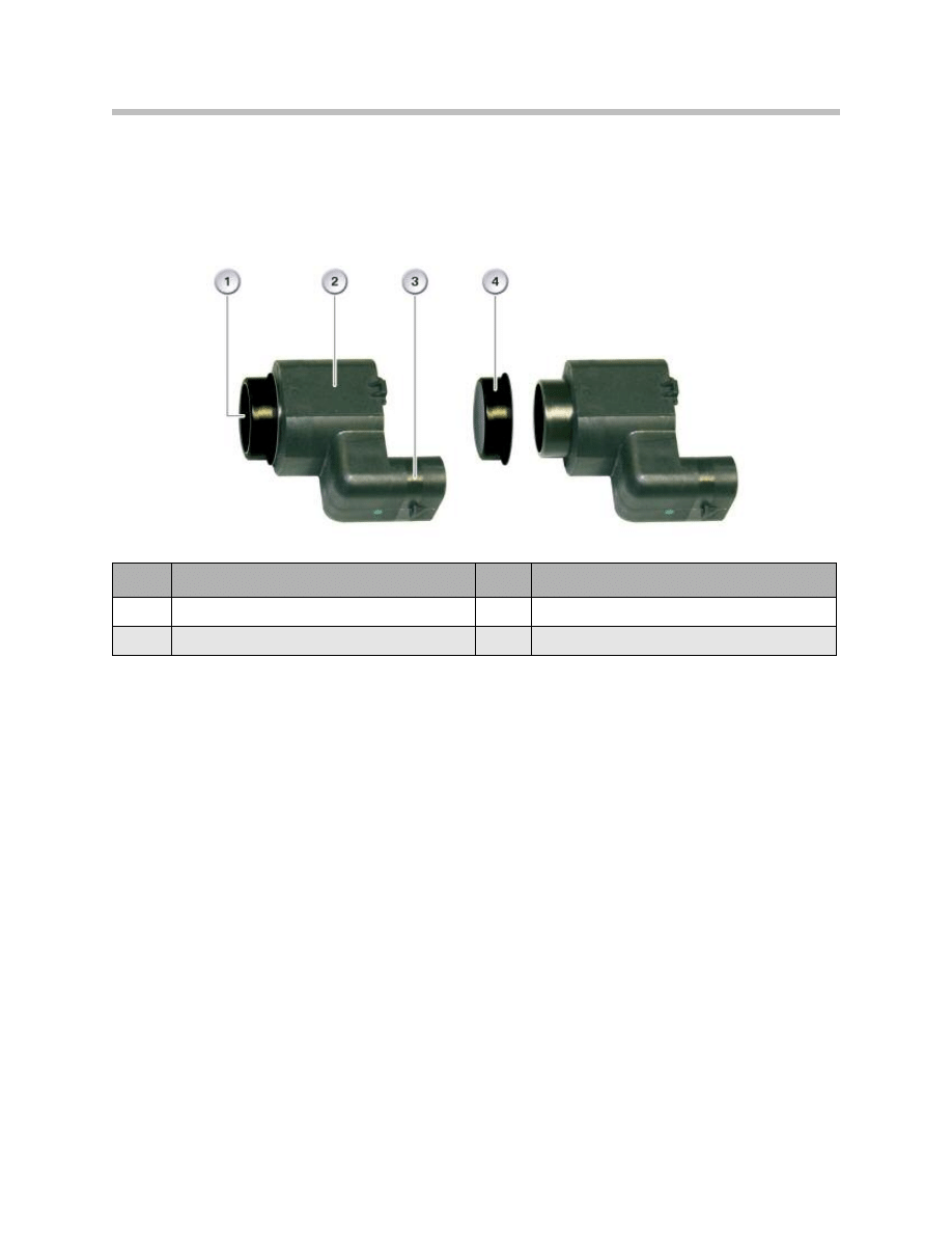
The installation of the De-coupling ring is essential and ensures trouble-free operation.
The transmission and reception quality may be reduced if no or an incorrect De-coupling
ring is fitted. In addition, the park distance control can trigger a continuous tone although
there is no obstacle in the detection range of the ultrasonic sensor. The De-coupling ring
does not serve as a seal.
The ultrasonic sensors can amplify the echo signals and convert them into digital signals.
A bidirectional data line is used for transmitting data to the park distance control. For this
reason, all ultrasonic sensors are connected by means of a 3-pin waterproof plug con-
nection to the wiring harness.
Electrically and mechanically, all ultrasonic sensors are of identical design. Adaptation to
the respective bumper is achieved by way of variant encoding. These data are specific to
the type and vehicle and depend on the installation location.
To ensure the ultrasonic sensors can be used universally, the corresponding data are sent
from the park distance control module to the ultrasonic sensors every time the park dis-
tance control is activated.
This means the ultrasonic sensors of one vehicle can be interchanged as part of a trou-
bleshooting procedure.
15
E70 Park Distance Control
Index
Explanation
Index
Explanation
1
Outer diaphragm
3
Connection socket
2
Sensor housing
4
De-coupling ring

Wiring harness, front ultrasonic sensors
The wiring harness is one-piece from the control unit up to the bumper, where the wiring
harness is split and connected to the individual ultrasonic sensors.
Wiring harness, rear ultrasonic sensors
The wiring harness is one-piece from the control unit up to the bumper, where the wiring
harness is split and connected to the individual ultrasonic sensors.
Power supply of ultrasonic sensors
The positive connection and ground connection are routed individually up to the bumper.
The power supply is split in the bumper and routed to the ultrasonic sensors.
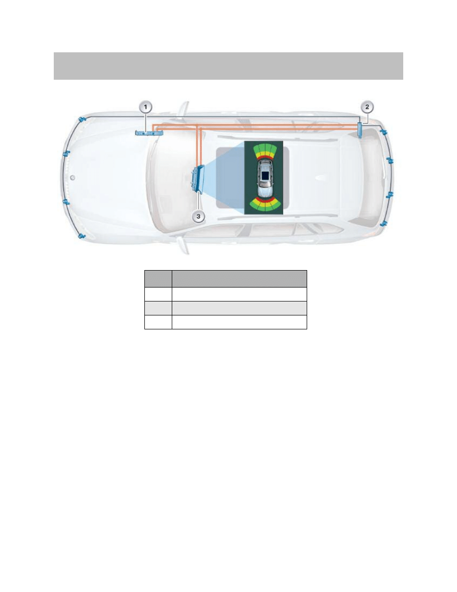
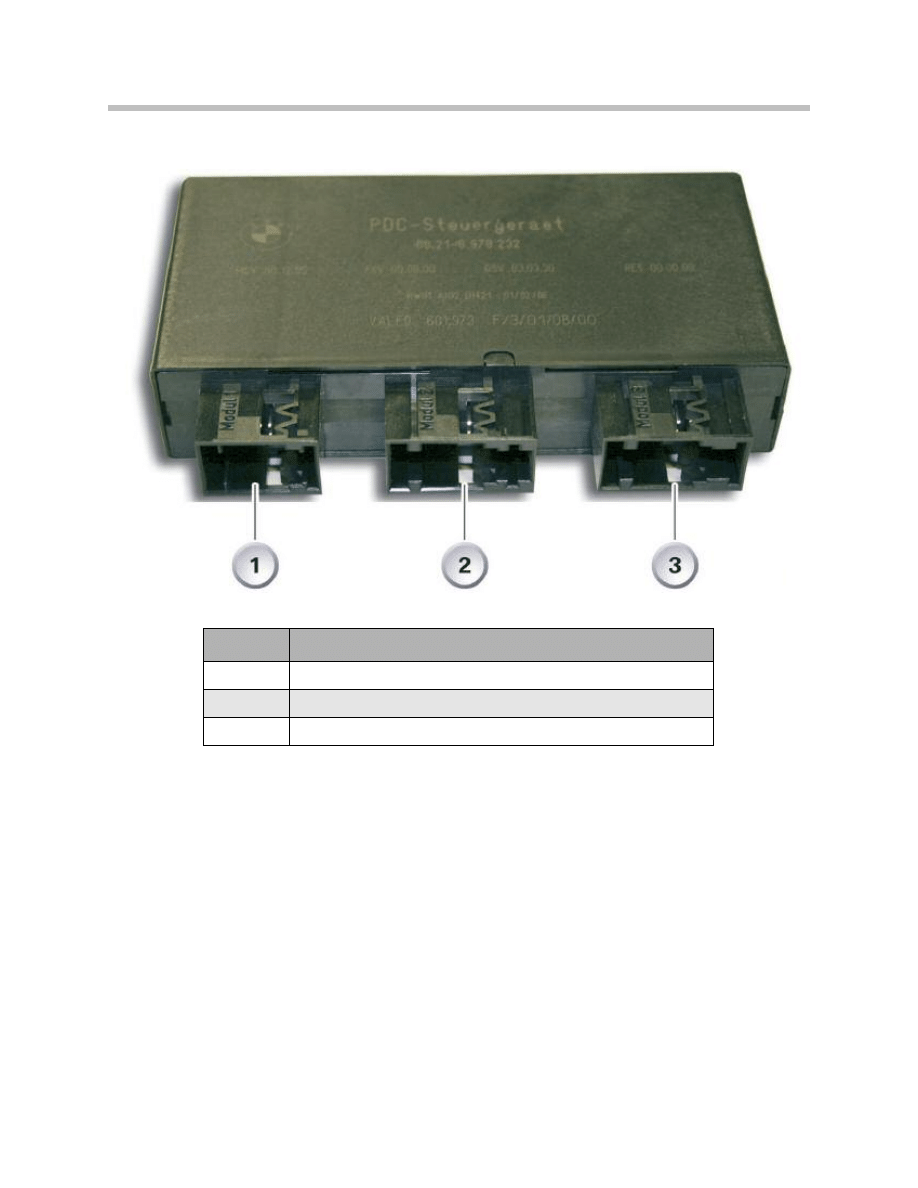
Park Distance Control with Eight Channels
The control unit for the park distance control in the E70 is an 8-channel system.
Activation of the audible and visual distance signalling is dependent on the audio system.
The park distance control unit is installed on the rear right in the luggage compartment.
The park distance control unit has three connectors for the version with four sensors for
the front and four sensors for the rear area of the vehicle
16
E70 Park Distance Control
Park Distance Control Functions
The main functions of the park distance control are:
• To activate the ultrasonic sensors
• To evaluate the received echo pulses
• To output the signals for audible and visual driver information
• Bus communication
The park distance control additionally monitors correct operation of all ultrasonic sensors.
In the event of a fault, the corresponding message is indicated to the driver (check control
message) and the fault code is stored in the fault code memory. The park distance con-
trol (control unit) is constantly operational as from "Terminal 15 ON" even if the function is
not active.
17
E70 Park Distance Control
Park Distance Control Module
Index
Explanation
1
Connection, bus
2
Connection, rear sensors
3
Connection, front sensors

Diagnosis
The ultrasonic sensors must be clean and free of ice to ensure effective operation.
Check following points before performing the diagnostic procedure:
• Check mechanical condition of ultrasonic sensors. Make sure that the ultrasonic
sensors are fitted correctly in their retaining fixtures and are free of dirt, ice and
snow. A reoccurring fault symptom is that the customer complains about the con-
tinuous tone in the park distance control but the system operates correctly in the
workshop. This problem is caused by ice or dirt on the sensors.
• During troubleshooting, there must be no objects closer than 40 cm from the
detection range of the ultrasonic sensors.
• Ensure the De-coupling element is fitted correctly on the ultrasonic sensor.
Otherwise problems may be encountered in transmitting and receiving signals.
The park distance control unit monitors the following system components for breaks
(open circuit) or short-circuits and if problems occur corresponding fault codes are
stored in the fault code memory:
• Data lines to the ultrasonic sensors
• Power supply of the ultrasonic sensors
System Limits
The park distance control cannot replace the driver's own estimation of the distance to
obstacles. Sensors also have a "dead" zone in which objects can no longer be detected.
Detection of objects can come up against the physical limits of ultrasonic measurement
when the ultrasonic waves are not or poorly reflected, e.g. thin objects. Low objects
already indicated can "disappear" again before a continuous tone is sounded (a high
curb stone). Loud sources of noise outside and within the vehicle can drown out the sig-
nal tone of the park distance control. The driver therefore remains responsible for esti-
mating obstacles even in vehicles equipped with park distance control.
18
E70 Park Distance Control
Service Information
The park distance control can trigger a warning under the following conditions even
though there is no obstacle in the detection range:
• Ultrasonic sensor not fitted correctly in its retaining fixture
• In heavy rain
• Ultrasonic sensors dirty or iced up
• Ultrasonic sensors covered in snow
• Exhaust gasses
• Echo pulses caused by the natural surroundings, like extremely rough road surface
or grass
• In large, rectangular rooms with smooth walls, like in underground parking garages
(superimposition of reflected echo pulses)
• Fault triggered by connected towing hitch or of unevenly fitted cap on ball head of
towing hitch.
Cleaning the Ultrasonic Sensors
The ultrasonic sensors must be clean and free of ice to ensure effective operation. When
washing the vehicle with a high pressure washer, do not direct the spray continuously at
the ultrasonic sensors and maintain a minimum distance of 10 cm.
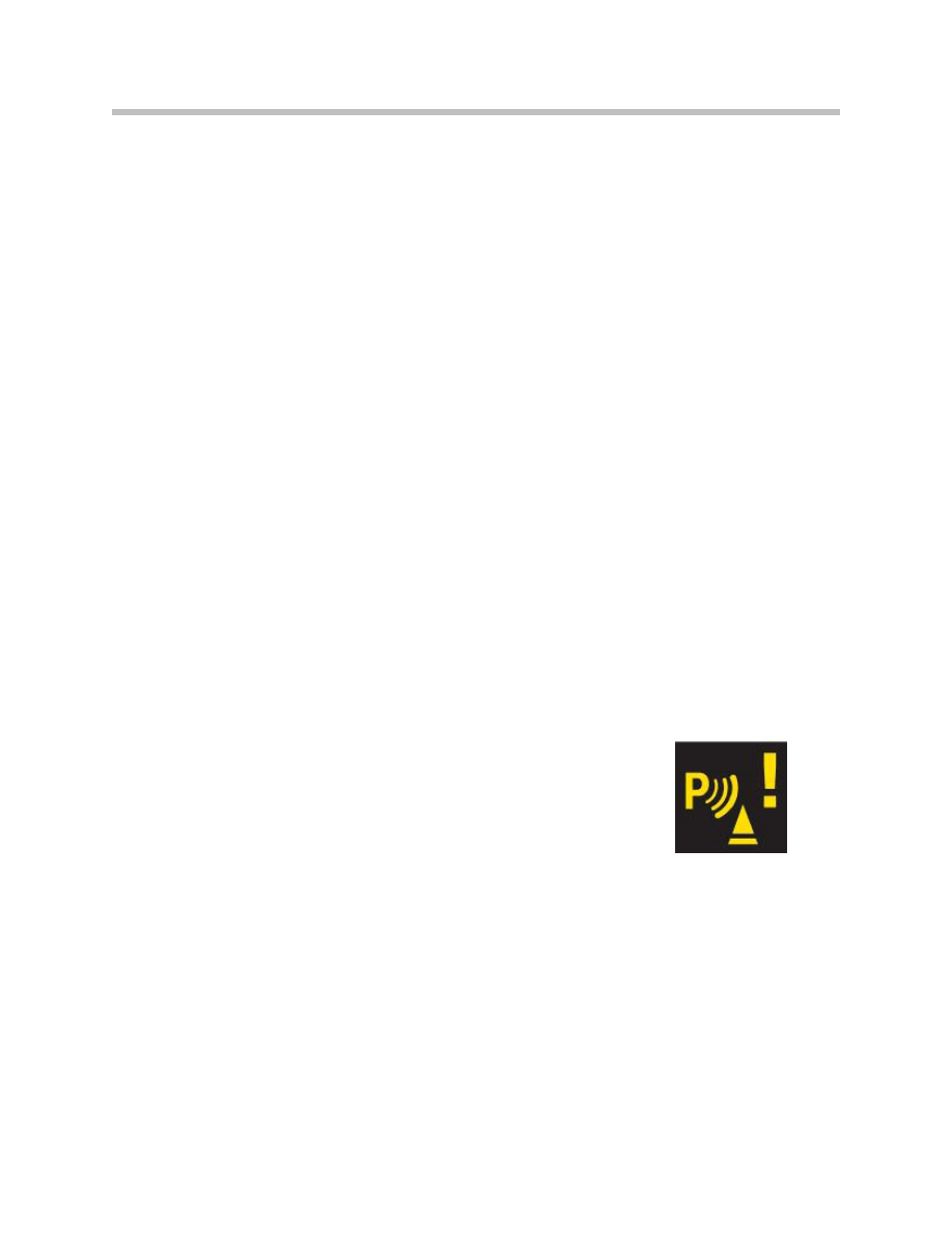
System Error
A check control message is shown in the instrument cluster and in the central informa-
tion display to indicate a fault in the park distance control.
This symbol appears in the instrument cluster.
In addition, the following text appears in the status line of the
central information display:
• "PDC failed"
• The following text can be selected in the "Check control messages" sub-menu of
the "BMW Service" menu.
• "Park Distance Control (PDC) failed. Have the problem checked by your BMW dealer
as soon as possible."
19
E70 Park Distance Control
Document Outline
- Main Menu
- E70 Introduction
- E70 Glovebox
- E70 Powertrain
- E70 Gasoline Engines
- E70 Transmissions
- E70 Voltage Supply and Bus Systems
- E70 Car Access System 3
- E70 Energy Management
- E70 Chassis Dynamics
- E70 Lateral Dynamics Systems
- E70 Vertical Dynamics Systems
- E70 Longitudinal Dynamics Systems
- E70 Central Locking
- E70 Power Windows
- E70 Comfort Access
- E70 Wipe/Wash System
- E70 Panorama Glass Sunroof
- E70 Seats
- E70 Automatic Tailgate
- E70 Steering Column Switch Cluster
- E70 Exterior Lighting
- E70 Interior Lighting
- E70 Adaptive Headlight System
- E70 Park Distance Control
- E70 Rear-view Camera
- E70 Anti-Theft Alarm System
- E70 Outside Mirrors
- E70 Displays Indicators and Controls
- E70 Head-up Display
- E70 Information and Communication
- E70 Audio Systems
- E70 Rear Seat Entertainment
- E70 Climate Control Systems
- E70 Passive Safety Systems
Wyszukiwarka
Podobne podstrony:
22 E65 Park Distance Control
07b E65 Park Distance Control
08 E70 Climate Control WB
06a E70 Displays Indicators and Controls
Kim Control of auditory distance perception based on the auditory parallax model
Park Narodowy Salonga
Damage Control Plan
Slowinski Park Narodowy (prezentacja)
Drawieński Park Narodowy(1)
Gorczański Park Narodowy (prezentacja)
Biebrzaski Park Narodowy
Park Narodowy Gór Stołowych (prezentacja)
14 Controllingid 15298 ppt
Controlling w przedsiębiorstwie
overview simatic controllers 04 2007 en plc
Koźminek Pałac i park w Koźminku
Control System Toolbox
control el heater pl
więcej podobnych podstron