
STEERING
TABLE OF CONTENTS
page
page
POWER STEERING SYSTEM – 2.5L VM
DIESEL . . . . . . . . . . . . . . . . . . . . . . . . . . . . . . . . . 1
POWER STEERING PUMP – 2.5L VM DIESEL . . . 2
POWER STEERING SYSTEM – 2.5L VM DIESEL
TABLE OF CONTENTS
page
DESCRIPTION AND OPERATION
POWER STEERING PUMP . . . . . . . . . . . . . . . . . . 1
DESCRIPTION AND OPERATION
POWER STEERING PUMP
The power steering pump used with the 2.5L VM
Diesel engine operates the same way as the power
steering pump used with the 2.5/4.0L gasoline
engines. Refer to the Description and Operation sec-
tion for the 2.5/4.0L gasoline engine power steering
pump for more information.
XJ
STEERING
19 - 1
POWER STEERING PUMP – 2.5L VM DIESEL
TABLE OF CONTENTS
page
page
SERVICE PROCEDURES
OPERATION . . . . . . . . . . . . . . . . . . . . . . . . . . . . 2
REMOVAL AND INSTALLATION
POWER STEERING PUMP — LHD . . . . . . . . . . . . 2
POWER STEERING PUMP — RHD . . . . . . . . . . . . 5
STEERING GEAR - RHD . . . . . . . . . . . . . . . . . . . . 7
SERVICE PROCEDURES
POWER STEERING PUMP - INITIAL
OPERATION
WARNING: THE
FLUID
LEVEL
SHOULD
BE
CHECKED WITH ENGINE OFF TO PREVENT INJURY
FROM MOVING COMPONENTS.
CAUTION: Use MOPAR Power Steering Fluid or
equivalent. Do not use automatic transmission fluid
and do not overfill.
Wipe filler cap clean, then check the fluid level.
The dipstick should indicate COLD when the fluid is
at normal ambient temperature.
(1) Fill the pump fluid reservoir to the proper level
and let the fluid settle for at least two minutes.
(2) Start the engine and let run for a few seconds
then turn engine off.
(3) Add fluid if necessary. Repeat the above proce-
dure until the fluid level remains constant after run-
ning the engine.
(4) Raise the front wheels off the ground.
(5) Slowly turn the steering wheel right and left,
lightly contacting the wheel stops at least 20 times.
(6) Check the fluid level add if necessary.
(7) Lower the vehicle, start the engine and turn
the steering wheel slowly from lock to lock.
(8) Stop the engine and check the fluid level and
refill as required.
(9) If the fluid is extremely foamy or milky look-
ing, allow the vehicle to stand a few minutes and
repeat the procedure.
CAUTION: Do not run a vehicle with foamy fluid for
an extended period. This may cause pump damage.
REMOVAL AND INSTALLATION
POWER STEERING PUMP — LHD
Removal
(1) Disconnect the negative battery cable.
(2) Remove the A/C line support bracket from the
rear of the rocker cover.
(3) Disconnect the A/C compressor electrical con-
nector.
(4) Remove the (2) engine mount upper sill plate
nuts (Fig. 1).
(5) Make
sure
the
steering
wheel
is
in
the
unlocked position.
(6) Raise the vehicle on a hoist.
(7) Remove the steering shaft pinch bolt and slide
the steering shaft straight off the gearbox input
shaft, position the shaft aside.
Fig. 1 Engine Mount Sill Plate Nuts
1 – SILL PLATE NUTS
2 – STEERING SHAFT
3 – ENGINE MOUNT
19 - 2
STEERING
XJ
CAUTION: Avoid turning the steering shaft while
disconnected from the steering gearbox. Damage to
steering column clockspring could occur.
(8) Remove the power steering fluid supply hose
from the pump and let the fluid drain.
(9) Loosen the (4) H-Block retaining bolts. Do not
remove the bolts at this time.
(10) Remove the accessory drive belt from the
power steering pump pulley. Refer to Group 7, Cool-
ing System for procedure.
(11) Remove the power steering pump pulley. Use
a hex socket to secure the pump shaft while remov-
ing the pulley nut with a box wrench (Fig. 2).
NOTE: Mark the position of the H-Block in relation
to the A/C Compressor so it may be reinstalled in
the same position.
(12) Remove the (2) bolts retaining the H-Block to
the power steering pump shaft coupler.
(13) Loosen the coupler pinch bolt and slide the
coupler towards the pump.
(14) Remove the power steering pump pressure
line from the steering gear. This is more accessible,
but will require you to install the pressure line on
the new pump prior to installation.
(15) Remove the remaining 2 bolts from the
H-Block and remove the H-Block from the compres-
sor.
(16) Support the A/C compressor with mechanics
wire before proceding to the next step.
(17) Remove the (4) A/C compressor retaining
bolts.
(18) Remove the left engine mount throughbolt nut
only. Do not remove the bolt at this time.
(19) Position a jack stand and raise weight off left
engine mount.
(20) Remove the track bar support bracket retain-
ing bolts and remove bracket (Fig. 3).
(21) Remove the lower engine mount bolt from the
sill plate (Fig. 3).
(22) Remove the (4) engine mount bracket bolts
from the engine block.
(23) Remove the engine mount throughbolt.
(24) Remove the engine mount and engine mount
bracket from the vehicle.
(25) Remove the (2) power steering pump retaining
nuts (Fig. 4).
(26) Remove the power steering pump from the
vehicle.
Installation
WARNING: Power steering system fluid may be
contaminated with metal shavings, overheated or
improper fluid. All fluid should be drained from the
system.
After
component
replacement,
system
should be flushed and filled with Mopar Power
Steering Fluid, or equivalent.
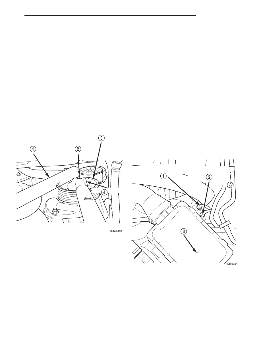
Fig. 2 Removing the Power Steering Pump Pulley
1 – LEVERAGE PIPE
2 – HEX WRENCH
3 – POWER STEERING PUMP PULLEY
4 – BOX WRENCH
Fig. 3 Engine Mount Retaining Bolts
1 – TRACK BAR SUPPORT BRACKET RETAINING BOLTS
2 – ENGINE MOUNT SILL PLATE BOLT
XJ
STEERING
19 - 3
REMOVAL AND INSTALLATION (Continued)
(1) Transfer the pressure line to the new pump,
making sure line is in original position.
(2) Transfer the coupler to the new pump leaving
pinch bolt lose at this time (Fig. 5).
(3) Install the power steering pump (Fig. 5).
(4) Install the engine mount and the engine mount
bracket in the vehicle.
(5) Install the engine mount throughbolt and leave
loose at this time.
(6) Install, but do not torque the engine mount
and track bar support bracket bolts (Fig. 6).
(7) Install the (4) engine mount bracket to engine
block retaining bolts. Torque bolts to 47 N·m (35 ft.
lbs.).
(8) Torque the engine mount sill plate bolts to 41
N·m (30 ft. lbs.).
(9) Torque the larger trackbar support bracket
bolts to 125 N·m (92ft. lbs.).
(10) Remove the jack stand.
(11) Install the H-Block on the A/C compressor in
its original position and leave the bolts loose at this
time.
(12) Position and install the A/C compressor.
(13) Slide the drive coupler in its original position
and install the remaining (2) H-Block bolts.
(14) Install the power steering pump pulley (Fig.
7). Torque nut to 166 N·m (120 ft. lbs.).
(15) Install the accessory drive belt. See Group 7,
Cooling System for procedure.
(16) Torque all the H-Block bolts.
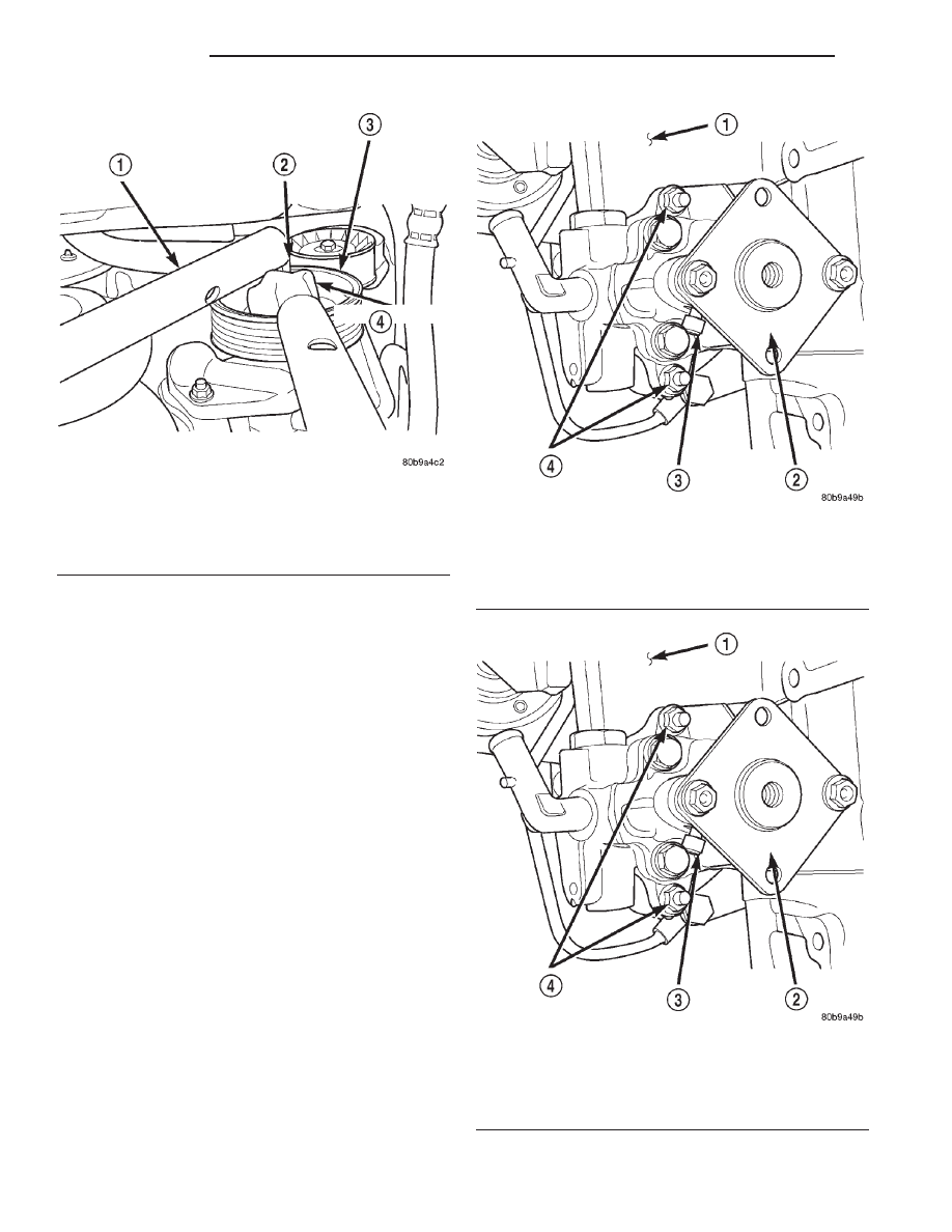
Fig. 4 Power Steering Pump
1 – ENGINE BLOCK
2 – COUPLER
3 – COUPLER PINCH BOLT
4 – POWER STEERING PUMP RETAINING NUTS
Fig. 5 Power Steering Pump
1 – ENGINE BLOCK
2 – COUPLER
3 – COUPLER PINCH BOLT
4 – POWER STEERING PUMP RETAINING NUTS
Fig. 6 Engine Mount Retaining Bolts
1 – TRACK BAR SUPPORT BRACKET RETAINING BOLTS
2 – ENGINE MOUNT SILL PLATE BOLT
19 - 4
STEERING
XJ
REMOVAL AND INSTALLATION (Continued)
(17) Install the steering shaft. Torque the steering
shaft pinch bolt to 49 N·m (36 ft. lbs.).
(18) Install the pressure line on steering gear.
Torque nut to 28 N·m (21 ft. lbs.).
(19) Install the power steering fluid supply hose on
the pump.
(20) Lower the vehicle from the hoist.
(21) Install and torque the engine mount upper sill
plate nuts to 41 N·m (30 ft. lbs.) (Fig. 8).
(22) Connect the A/C compressor electrical connec-
tor.
(23) Install the A/C line support bracket bolt at the
rear of the valve cover.
(24) Fill the power steering fluid. See Group 19,
Steering for Power Steering Pump-Initial operation
procedure.
(25) Connect the negative battery cable.
POWER STEERING PUMP — RHD
Removal
(1) Disconnect the negative battery cable.
(2) Remove the refrigerent line support bracket
bolt from the top of the radiator.
(3) Remove the A/C filter-drier assembly support
bracket nuts from left fender well.
(4) Disconnect the A/C compressor electrical con-
nector.
(5) Raise the vehicle on a hoist.
(6) Remove the power steering fluid supply hose
from pump and drain fluid.
(7) Remove power steering line support bracket
bolt from below radiator.
(8) Remove the engine mount upper sill plate nuts.
(9) Loosen the (4) H-Block retaining bolts. Do not
remove at this time.
(10) Remove the accessory drive belt from the
power steering pump pulley. See Group 7, Cooling
System for procedure.
(11) Remove the power steering pump pulley. Use
a hex socket to secure the pump shaft while remov-
ing the pulley nut with a box wrench (Fig. 9).
NOTE: Mark position of the H-Block in relation to
the A/C Compressor so it can be installed in the
same position.
(12) Remove the (2) bolts retaining the H-Block to
the power steering pump shaft coupler.
(13) Loosen the coupler pinch bolt and slide cou-
pler towards pump.
(14) Remove the left engine mount throughbolt nut
only. Do not remove the bolt at this time.
(15) Remove the remaining 2 bolts from the
H-Block and remove the H-Block from the compres-
sor.
(16) Position a jack stand and raise weight off left
engine mount.
(17) Remove the (2) engine mount sill plate bolts.
(18) Remove the (4) engine mount bracket bolts
from the engine block.
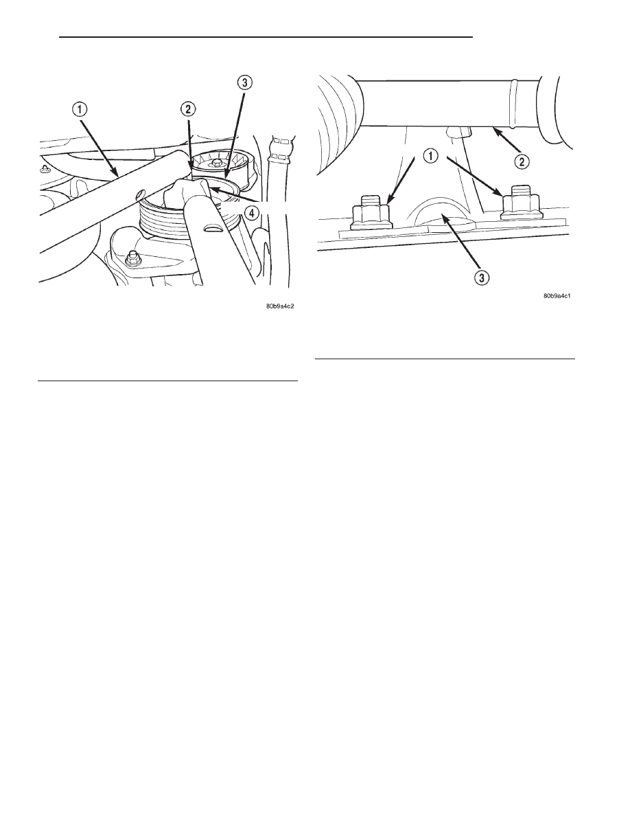
Fig. 7 Installing Pump Pulley
1 – LEVERAGE PIPE
2 – HEX WRENCH
3 – POWER STEERING PUMP PULLEY
4 – BOX WRENCH
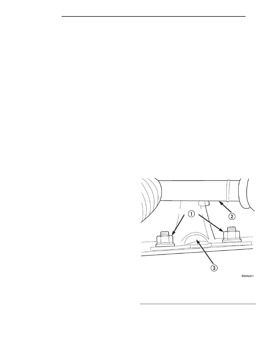
Fig. 8 Engine Mount Sill Plate Nuts
1 – SILL PLATE NUTS
2 – STEERING SHAFT
3 – ENGINE MOUNT
XJ
STEERING
19 - 5
REMOVAL AND INSTALLATION (Continued)
(19) Remove the engine mount throughbolt.
(20) Remove the engine mount and engine mount
bracket from vehicle.
(21) Remove the (2) power steering pump retaining
nuts (Fig. 10).
(22) Slide pump off mounting studs and position so
pressure line can be removed. This will require you
to install pressure line on the new pump prior to
installing it in the engine block.
(23) Remove the power steering pump from the
vehicle.
Installation
WARNING: Power steering system fluid may be
contaminated with metal shavings, overheated or
improper fluid. All fluid should be drained from the
system.
After
component
replacement,
system
should be flushed and filled with Mopar Power
Steering Fluid, or equivalent.
(1) Install the pressure line on pump in original
position.
(2) Transfer the drive coupler to new pump leaving
pinch bolt lose at this time (Fig. 11).
(3) Install the power steering pump in the engine
block. Torque retaining nuts to 24 N·m (18 ft. lbs.)
(Fig. 11).
(4) Install the engine mount and engine mount
bracket in vehicle.
Fig. 9 Removing Pump Pulley
1 – LEVERAGE PIPE
2 – HEX WRENCH
3 – POWER STEERING PUMP PULLEY
4 – BOX WRENCH
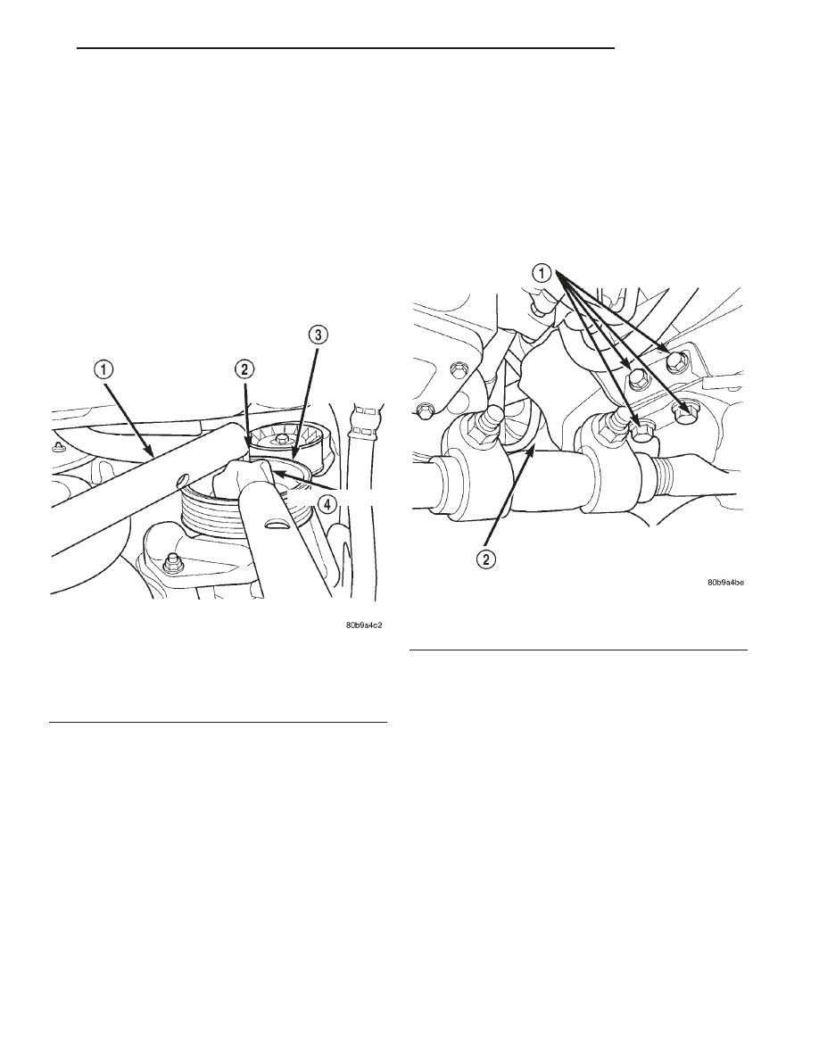
Fig. 10 Power Steering Pump
1 – ENGINE BLOCK
2 – COUPLER
3 – COUPLER PINCH BOLT
4 – POWER STEERING PUMP RETAINING NUTS
Fig. 11 Power Steering Pump
1 – ENGINE BLOCK
2 – COUPLER
3 – COUPLER PINCH BOLT
4 – POWER STEERING PUMP RETAINING NUTS
19 - 6
STEERING
XJ
REMOVAL AND INSTALLATION (Continued)
(5) Install the engine mount throughbolt and leave
loose at this time.
(6) Install, do not torque engine mount sill plate
nuts and bolts.
(7) Install (4) engine mount bracket to engine
block retaining bolts and Torque to 61 N·m (45 ft.
lbs.).
(8) Torque the engine mount sill plate nuts to 41
N·m (30 ft. lbs.).
(9) Torque the engine mount sill plate bolts to 41
N·m (30 ft. lbs.).
(10) Remove jack stand.
(11) Install the H-Block on the A/C compressor in
the original position and leave bolts loose at this
time.
(12) Position and install A/C compressor.
(13) Slide the drive coupler into its original posi-
tion and start remaining (2) H-Block bolts.
(14) Install the power steering pump pulley (Fig.
12). Torque nut to 166 N·m (120 ft. lbs.).
(15) Install the accessory drive belt. See Group 7,
Cooling for procedure.
(16) Torque all the H-Block bolts.
(17) Torque the engine mount throughbolt nut to
65 N·m (48 ft. lbs.).
(18) Install the power steering fluid supply hose on
pump.
(19) Install
the
power
steering
line
support
bracket bolt.
(20) Lower the vehicle from hoist.
(21) Install the refrigerent line support bracket
and bolt on the top of the radiator.
(22) Install the A/C filter-drier assembly support
bracket nuts on the left fender well.
(23) Reconnect the A/C compressor electrical con-
nector.
(24) Re-fill the power steering fluid. Refer to
Group 19, Steering for Power Steering Pump-Initial
Operation for procedure.
(25) Connect the negative battery cable.
STEERING GEAR - RHD
REMOVAL
(1) Open the hood and disconnect the negative bat-
tery cable.
(2) Place the front wheels in the straight ahead
position and lock the steering wheel.
CAUTION: Be certain to lock the steering wheel in
position prior to disconnecting the steering column
coupler. This will prevent clockspring damage.
(3) Disconnect the power steering pressure and
return lines from the steering gear (Fig. 13).
(4) Remove the steering column coupler pinch bolt.
Located just to the rear of the fluid lines (Fig. 13).
Fig. 12 Installing Pump Pulley
1 – LEVERAGE PIPE
2 – HEX WRENCH
3 – POWER STEERING PUMP PULLEY
4 – BOX WRENCH
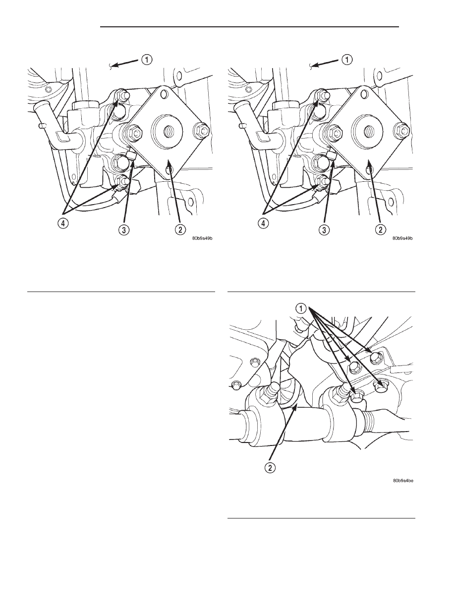
Fig. 13 Power Steering Fluid Pressure and Return
Line Location – RHD
1 – POWER STEERING FLUID RETURN LINE
2 – POWER STEERING FLUID PRESSURE LINE
3 – AIR FILTER COVER
XJ
STEERING
19 - 7
REMOVAL AND INSTALLATION (Continued)
(5) Separate steering shaft from gearbox by pulling
straight apart.
(6) Raise the vehicle on a hoist.
(7) Remove the stabilizer bar clamp retaining bolts
from the frame (Fig. 14). Allow stabilizer bar to hang
free.
(8) Remove the Pittman arm from the steering
gear (Fig. 14). Refer to Group 19, Steering for the
procedure.
(9) Remove the small right front splash from the
vehicle.
(10) Remove the (3) steering gear retaining bolts
(Fig. 15).
(11) Rotate the lower radiator hose clamp, so that
the tangs are facing straight down. This will aid in
gear removal.
(12) Remove the steering gear from the vehicle.
INSTALLATION
(1) Center the steering gear travel. Rotate gear
output shaft until stop. Make a reference mark in the
same position on the gear shaft and gear housing.
Rotate gear shaft in the opposite direction until stop
while noting the number of turns. Divide that num-
ber in half and position the reference mark made
previously at that position.
(2) Install the steering gear in the vehicle.
(3) Install the (3) steering gear retaining bolts.
Torque to 95 N·m (70 ft. lbs.).
(4) Install the small right front splash on the vehi-
cle.
(5) Install the Pittman arm on the steering gear.
Refer to Group 19, Steering for the procedure. Torque
nut to 251 N·m (185 ft. lbs.).
(6) Position the stabilizer bar and install the
clamp retaining bolts. Refer to Group 2, Suspension
for a detailed procedure. Torque the bolts to 75 N·m
(40 ft. lbs.).
(7) Lower the vehicle on the hoist.
(8) Install the steering column shaft coupler on the
steering gear and install pinch bolt. Torque the bolt
to 35 N·m (26 ft. lbs.)..
(9) Install the power steering pressure and return
lines on the steering gear. Torque the lines to 28 N·m
(21 ft. lbs.).
(10) Connect the negative battery cable.
(11) Check and correct vehicle front end alignment
specifications if necessary. Refer to Group 2, Suspen-
sion for the procedure.
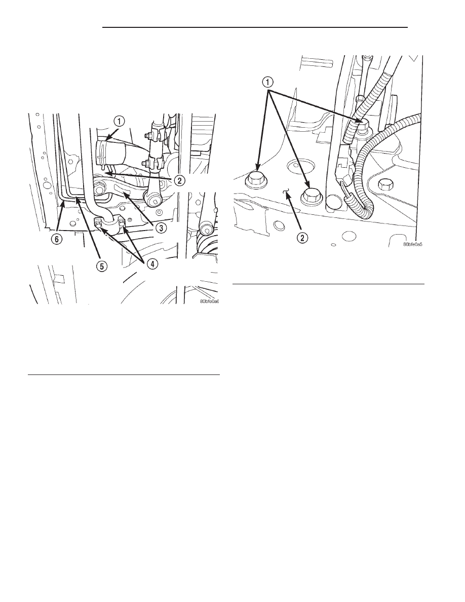
Fig. 14 Steering Gear
1 – LOWER RADIATOR HOSE/CLAMP
2 – STEERING GEAR
3 – PITMAN ARM
4 – STABILIZER BAR RETAINING BOLTS
5 – POWER STEERING FLUID PRESSURE LINE
6 – POWER STEERING FLUID RETURN LINE
Fig. 15 Steering Gear Retaining Bolts
1 – STEERING GEAR RETAINING BOLTS
2 – VEHICLE FRAME RAIL
19 - 8
STEERING
XJ
REMOVAL AND INSTALLATION (Continued)
Document Outline
Wyszukiwarka
Podobne podstrony:
KARTA KATALOGOWA n14 19a
karta pod, pit 19a v6
19a (2)
19a
Wykład 19a
19a
pd wykl pr 19a, Prawo morza
Księga 1. Proces, ART 479(19a) KPC, III CZP 55/09 - postanowienie z dnia 4 września 2009 r
test 2009 2010 fizyka, Stałe : c=2,998x108 m/s; e=1,602x10-19A*s; h=6,63x10⁻³⁴ J*s; NA
SIMR-AN1-EGZ-2007-06-19a-rozw
19a [Brahmi] Kannada starożytny
19a pracoholizm i mobbing
19a sieciocentryczność, Procesy informacyjne w zarządzaniu, materiały student Z-sem 12-13, wytyczne
1 19a
pit 19a PR2JLGKCDFYQGXEVSWN6POFYQH6RYQLLONGM6KQ
KARTA KATALOGOWA n14 19a
exj 8q
exj 6a
więcej podobnych podstron