
SECRET//REL TO USA, AUS, CAN, GBR, AND NZL//X1
TRMS No. 8-ES-685-IED-002
USAEPG Publication No. ATR04
−
04-014
USAEPG
Submitted by James Smith and James Billingsley
Test and Measurement Branch, Test Engineering Division
US Army Electronic Proving Ground
Fort Huachuca, Arizona 85613
−
7063
Approved for External Coordination by Alan Morris
Chief, Test and Measurement Branch, Test Engineering Division
US Army Electronic Proving Ground
Fort Huachuca, Arizona 85613–7063
May 2004
Abbreviated Test Report for Blue Force
Communications Electromagnetic Compatibility (EMC)
with WARLOCK-Red and WARLOCK-Green (U//FOUO)
SECRET//REL TO USA, AUS, CAN, GBR, AND NZL//X1
Distribution authorized to US
Government agencies and their
contractors; critical technology, May
2004. Other requests for this document
shall be referred to the Product
Manager, FIREFINDER, ATTN: SFAE-
IEW&S-FF, Fort Monmouth, NJ 07703-
5303
Not releasable to DTIC
CLASSIFIED BY: WARLOCK Security
Classification Guide, 11 March 2004
REASON: 4.1(A)(g)
DECLASSIFY ON: X1
Period:
March through April 2004
Prepared for:
Program Manager, Signals Warfare
ATTN: SFAE– IEW&S–SG (LTC John Masterson)
296 Sherrill Avenue
Fort Monmouth, NJ 07703–5303
US Army Developmental Test Command
Aberdeen Proving Ground, MD 21005–5055

UNCLASSIFIED
UNCLASSIFIED
(U) The views, opinions, and findings contained in this document reflect
those of the US Army Electronic Proving Ground and the authors and
should not be construed as an official Department of the Army position,
policy, or decision unless so designated by official documentation.
(U) This document was prepared using Security Classification Guide,
WARLOCK, Interim Draft, US Army Communications-Electronics
Command, 11 March 2004 (SECRET).
Destruction Notice (U)
(U) For classified documents, follow the procedures in DOD 5230-22-M,
NISPOM, Chapter 5, Section 7, DOD 5200.1R, Information Security
Program Regulation, Chapter IX, or Army Regulation 380-5, Department
of the Army Information Security Program, Chapter 3, Section V. For
unclassified, limited distribution documents, destroy by any method that
will prevent disclosure of contents or reconstruction of the document.
Disclaimer (U)
(U) The use of trade names in this report does not constitute an official
endorsement or approval of the use of such commercial hardware and
software. This report may not be cited for the purpose of advertisement.

SECRET//REL TO USA, AUS, CAN, GBR, AND NZL//X1
i
Table of Contents (U)
SECTION 1. EXECUTIVE DIGEST (U)....................................................................... 1-1
1.1 (U) SUMMARY ................................................................................................... 1-1
1.2 (U) TEST OBJECTIVE ....................................................................................... 1-1
1.3 (U) TESTING AUTHORITY ................................................................................ 1-1
1.4 (U) TEST CONCEPT.......................................................................................... 1-1
1.5 (U) SYSTEM DESCRIPTION ............................................................................. 1-3
1.5.1 (S) IED Countermeasure Systems ............................................................... 1-3
1.5.2 (U) Blue Force Communications Systems Tested........................................ 1-3
1.6 (U) CONCLUSIONS .......................................................................................... 1-4
1.7 (U) RECOMMENDATIONS ................................................................................ 1-5
SECTION 2. DETERMINATION OF FINDINGS (U).................................................... 2-1
2.1 (S) IED COUNTERMEASURES SYSTEMS IMPACT ON INTRACONVOY
COMMUNICATIONS................................................................................................. 2-1
2.1.1 (U) Objective.. .............................................................................................. 2-1
2.1.2 (U) Criteria.................................................................................................... 2-1
2.1.3 (U) Test Procedures. .................................................................................... 2-1
2.1.4 (U) Test Findings.......................................................................................... 2-3
2.1.5 (U) Technical Analysis.................................................................................. 2-5
2.2 (S) IED COUNTERMEASURES IMPACT ON BASE-TO-CONVOY
COMMUNICATIONS................................................................................................. 2-7
2.2.1 (U) Objective. ............................................................................................... 2-7
2.2.2 (U) Criteria.................................................................................................... 2-7
2.2.3 (U) Test Procedures. .................................................................................... 2-7
2.2.4 (U) Test Findings.......................................................................................... 2-9
2.2.5 (U) Technical Analysis................................................................................ 2-10
SECTION 3. APPENDICES (U) .................................................................................. 3-1
A. ABBREVIATIONS (U) .............................................................................................A-1
B. DISTRIBUTION LIST (U) ........................................................................................B-1
SECRET//REL TO USA, AUS, CAN, GBR, AND NZL//X1

UNCLASSIFIED
ii
INTENTIONALLY BLANK
UNCLASSIFIED

SECRET//REL TO USA, AUS, CAN, GBR, AND NZL//X1
SECRET//REL TO USA, AUS, CAN, GBR, AND NZL//X1
1-1
SECTION 1. EXECUTIVE DIGEST (U)
1.1 (U) SUMMARY
a. (S) The US Army Electronic Proving Ground (USAEPG), Fort Huachuca, Arizona,
conducted electromagnetic compatibility (EMC) testing on the effect of WARLOCK-Green and
WARLOCK-Red Improvised Explosive Device (IED) countermeasure systems on Blue Force
command and control (C
2
) communications. The testing was performed at the US Army Yuma
Proving Ground (YPG) during March and April 2004. Follow-on testing, encompassing Blue
Force Tracking (BFT), was performed at USAEPG.
b. (S) The use of WARLOCK-Red prevented usable (80 percent of messages received and
understood) Blue Force C
2
communications. This could be mitigated by using the jammer
standoff method or by shortening communications links and providing communications relay.
1.2 (U) TEST OBJECTIVE
(S) To determine the effect the WARLOCK-Green and WARLOCK-Red IED countermeasure
systems have on Blue Force C
2
communications systems’ performance when co-located in the
same vehicle or in close proximity to a vehicle and operated simultaneously during convoy
operations or when in close proximity to a major communications node; i.e., tactical operations
center (TOC).
1.3 (U) TESTING AUTHORITY
(S) USAEPG was tasked, through the US Army Developmental Test Command (DTC), to
conduct the Blue Force C
2
communications EMC testing for WARLOCK-Green and
WARLOCK-Red IED countermeasure systems in the Internal Test Directive FY04-040, and Test
Resource Management Information System (TRMS) No. 8-ES-685-IED-002.
1.4 (U) TEST CONCEPT
(S) Two high mobility, multipurpose, wheeled vehicles (HMMWVs) [M1035 softtop with armor
survivability kit (ASK) and M1026 hardtop], equipped with Blue Force C
2
systems and the
WARLOCK-Green and WARLOCK-Red IED countermeasure systems, were used to assess the
effects of simultaneous Blue Force C
2
communications and WARLOCK-Green and
WARLOCK-Red operations within a convoy. Blue Force C
2
systems that were installed in both
HMMWVs consisted of the Single Channel Ground and Airborne Radio System (SINCGARS);
Enhanced Position Location Reporting System (EPLRS) with Force XXI Battle Command,
Brigade and Below (FBCB2); BFT with FBCB2; SPITFIRE AN/PSC-5 Enhanced Manpack
Ultrahigh Frequency (UHF) Terminal (EMUT); and Precision Lightweight Global Positioning
System (GPS) Receiver (PLGR). In addition to the preceding Blue Force C
2
systems, testing was
conducted using handheld Motorola XTS 3000 and Garmin RINO Family Radio Service
(FRS)/General Mobile Radio Service (GMRS) systems. Internal and external convoy C
2
communications were replicated and included intraconvoy and interconvoy scenarios.

SECRET//REL TO USA, AUS, CAN, GBR, AND NZL//X1
SECRET//REL TO USA, AUS, CAN, GBR, AND NZL//X1
1-2
(1) (U) The intraconvoy scenario replicated communications within a convoy; i.e.,
lead-vehicle-to-trail vehicle and trail-vehicle-to-lead vehicle communications. For intraconvoy
operations, a convoy length distance of 2 kilometers (km) was assumed as a realistic operational
distance from the lead vehicle to the trail vehicle.
(2) (S) The interconvoy scenario replicated communications between a TOC and a
convoy. A C
2
communications link distance of 20 km was assumed as a realistic operational
distance from the TOC to convoy. Transmitter output power scaling and/or transmit link attenu-
ation was used to replicate the 20-km communications link and provide realistic signal levels to
the destined receivers. During the interconvoy scenario execution, four IED countermeasure
system configurations were tested. Table 1 provides the IED countermeasure systems’ config-
urations for the interconvoy scenario.
Table 1. (S) IED Countermeasure System Interconvoy Configurations
IED Countermeasure System Configurations
IED Countermeasure
System
Configuration
1
Configuration
2
Configuration
3
Configuration
4
WARLOCK-Green
Off Off Off On
WARLOCK-Red Off On Off Off
SECRET
(3) (S) Communications link quality was measured for both intraconvoy and inter-
convoy scenarios. Table 2 provides the quality metrics used to assess the Blue Force C
2
communications transmission performance during simultaneous operations with the IED
countermeasure systems.
Table 2. (U) Blue Force C
2
Communications Transmission Success Quality Metrics
Blue Force C
2
System
Performance Standard
SINCGARS
Message Completion Rate (MCR), Radio SYNC
EPLRS/FBCB2
MCR, Final MCR (60 seconds after last C
2
message was transmitted)
BFT/FBCB2
MCR, Final MCR (60 seconds after last C
2
message was transmitted)
SPITFIRE
Subjective Voice Quality Measurement
Motorola XTS 3000
Subjective Voice Quality Measurement
Garmin RINO FRS/GMRS
Subjective Voice Quality Measurement
SECRET

SECRET//REL TO USA, AUS, CAN, GBR, AND NZL//X1
SECRET//REL TO USA, AUS, CAN, GBR, AND NZL//X1
1-3
1.5 (U) SYSTEM DESCRIPTION
1.5.1 (S) IED Countermeasure Systems
1.5.1.1 (S) WARLOCK-Green.
The WARLOCK-Green is a programmable, passive IED
jammer. It scans a series of target frequency bands, then transmits a jamming signal upon
detection of activity in that frequency band. It currently operates from approximately 20
megahertz (MHz) to approximately 500 MHz. It transmits at 25 watts (W) of power using a
single antenna.
1.5.1.2 (S) WARLOCK-Red.
The WARLOCK-Red is a programmable, active IED jammer. It
comprises two basic units, each of which targets different frequency bands. The WARLOCK-
Red low band operates from approximately 20 MHz to approximately 100 MHz. It transmits at 5
W of power using a modified SINCGARS whip antenna. The WARLOCK-Red midband
operates from approximately 250 MHz to approximately 500 MHz. It transmits at 1 W of power
using the same antenna as the WARLOCK-Green system.
1.5.2 (U) Blue Force Communications Systems Tested
1.5.2.3 (U) SINCGARS.
The SINCGARS is a very high frequency (VHF) radio. It has
capability for both voice and data; however, it is primarily used for voice C
2
. SINCGARS
operates using two modes: frequency hopping (FH) and single channel (SC). The system can
operate on any of the 2,320 available frequencies in the 30–87.975 MHz band, and can transmit
up to 50 W.
1.5.2.2 (U) EPLRS/FBCB2.
EPLRS/FBCB2 is a part of Blue Force communications equip-
ment. EPLRS/FBCB2 displays situational awareness (SA) on the computer monitor and uses the
UYK-128. It uses a PLGR to obtain its location and an EPLRS to send the data out. The EPLRS
1720-B radio is used for data communications; it operates in the UHF band 420–450 MHz. The
output power modes are 0.4, 3, 20, or 100 W. EPLRS has spread spectrum capability to prevent
jamming effects. Additionally, each radio in the network serves as an automatic repeater to
ensure reliable delivery of messages.
1.5.2.3 (U) Motorola XTS 3000 Handheld Radio.
The XTS 3000 is an analog/digital
handheld radio that provides two-way communication. It is a programmable, multichannel
analog radio capable of operating in the 400-MHz frequency range. The radio can function in
either split frequency, trunked repeater networks, or in peer-to-peer line of sight (LOS)
applications. The XTS 3000 provides both single- and dual-digital encryption. The XTS 3000
can operate under two basic modes, LOS point-to-point and in a trunked repeater network. The
three frequency ranges that the XTS 3000 transmits under are VHF, 136–174 MHz, 1–5 W;
UHF, 403–470 MHz (Range 1), 450–520 MHz (Range 2), 1–4 W; and the 800 MHz, 806–824
MHz (Range 1), 851–870 MHz (Range 2), 3 W.

SECRET//REL TO USA, AUS, CAN, GBR, AND NZL//X1
SECRET//REL TO USA, AUS, CAN, GBR, AND NZL//X1
1-4
1.5.2.4 (U) Garmin RINO FRS/GMRS Handheld Radio.
The RINO is an integrated GPS
handheld radio that provides two-way communication. It is a 22-channel consumer product radio
capable of operating in both the FRS band and the GMRS band. The radio functions only in
nonrepeater LOS terrestrial
mode.
It is capable of using the FRS band, 462.5625–467.7125
MHz, and the GMRS band, 462–467 MHz. The RINO has 22 communication channels, 14 FRS
channels, and 8 GMRS channels. The RINO can transmit at 0.5 W on low power using FRS, and
1 W on high power using GMRS.
1.5.2.5 (U) BFT.
BFT/FBCB2 is a part of Blue Force communications equipment that displays
SA on the computer monitor. The BFT consists of a UYK-128, which consists of the computer,
the monitor, and the display, and an MT2011 mobile satellite transceiver with power module.
The MT2011 sends the SA data back and forth between the transceivers. The MT2011 has
embedded GPS capabilities, operates in the L-Band frequency range, 1.530–2.700 GHz, and can
transmit up to 5 W.
1.5.2.6 (U) SPITFIRE.
The AN/PSC-5D Multiband Multimission Radio (MBMMR) is a radio
that has capabilities for UHF/VHF Manpack LOS communications and satellite communications/
demand assigned multiple access (SATCOM/DAMA). The PSC-5D, which has voice and data
capabilities, operates in the 30–512 MHz range. The PSC-5D has embedded communications
security (COMSEC) using a variety of encryption modes. The PSC-5D can transmit up to 10 W
in amplitude modulation (AM) and frequency modulation (FM) mode and up to 20 W in
SATCOM mode.
1.6 (U) CONCLUSIONS
a. (S) Impact on SINCGARS. Operation of WARLOCK-Red in the same vehicle
prevented communications using SINCGARS. Using the WARLOCK-Red in vehicles located 50
meters distant from vehicles using Blue Force communications allows usable communications.
Greatly shortening the LOS terrestrial (nonsatellite) radio frequency (RF) link distance allows
use of the WARLOCK-Red within the same vehicle.
b. (S) Impact on EPLRS/FBCB2. Operation of WARLOCK-Red in the same vehicle
prevented communications using EPLRS/FBCB2. Using the WARLOCK-Red located 50 meters
distant allows usable communications. Greatly reducing the LOS terrestrial (nonsatellite) RF
links allows use of the WARLOCK-Red within the same vehicle.
c. (S)
Impact on BFT/FBCB2.
Operation of WARLOCK-Red in the same vehicle
prevented communications using BFT/FBCB2. WARLOCK-Green impact on BFT/FBCB2 was
not tested. Using the WARLOCK-Red in vehicles located 50 meters distant allows usable
communications.
d. (S) Impact on Motorola XTS 3000 Handheld Radios. Operation of WARLOCK-Red or
the WARLOCK-Green within 50 meters of the Motorola handhelds prevented usable
communications. Jammer standoff distances greater than 50 meters were not tested due to
insufficient time.

SECRET//REL TO USA, AUS, CAN, GBR, AND NZL//X1
SECRET//REL TO USA, AUS, CAN, GBR, AND NZL//X1
1-5
e. (S)
Impact on Garmin RINO FRS/GMRS Handheld Radios. Operation of WARLOCK-
Red in the same vehicle prevented communications using the RINO radios. Jammer standoff
distances greater than 50 meters were not tested.
f. (S) Impact on SPITFIRE (AN/PSC-5).
Communications were not affected by either of
the IED jammers.
g. (S) Impact on GPS PLGR. Operation can be severely degraded if the WARLOCK-Red
antenna is mounted too close to the GPS PLGR antenna.
1.7 (U) RECOMMENDATIONS
a. (S) The SINCGARS and EPLRS used Iraq frequency resources for this test effort. The
SINCGARS hopsets and EPLRS channel resources contained frequencies used by the IED
jammer. The option of Blue Force communications frequency management should be explored
through follow-on EMC testing of the IED jammer systems with SINCGARS and EPLRS.
b. (S) The IED jammers should be mounted in vehicles that do not require Blue Force
communications, assuming the IED jammers can protect multiple vehicles.
c. (S) Additional EPLRS-equipped vehicles should be added to the convoys to provide
automatic relay capabilities for Blue Force SA and C
2
digital messaging.
d. (S) Maintain as much physical separation between GPS PLGR antennas and IED
jammer antennas as possible when both systems are mounted on the same vehicle.

UNCLASSIFIED
UNCLASSIFIED
1-6
INTENTIONALLY BLANK

SECRET//REL TO USA, AUS, CAN, GBR, AND NZL//X1
SECRET//REL TO USA, AUS, CAN, GBR, AND NZL//X1
2-1
SECTION 2. DETERMINATION OF FINDINGS (U)
2.1 (S) IED COUNTERMEASURES SYSTEMS IMPACT ON INTRACONVOY COM-
MUNICATIONS
2.1.1 (S) Objective.
The objective was to determine whether operating IED receiver jamming
systems (WARLOCK-Red, WARLOCK-Green) degraded Blue Force communications within a
convoy. Additional objectives were to determine mitigation techniques that allow simultaneous
operations when both types of systems are co-located.
2.1.2 (S) Criteria.
Simultaneous operation of co-located IED jammers and Blue Force
communications equipment shall not degrade Blue Force communications.
2.1.3 (S) Test Procedures.
Test personnel postulated that one of the most likely com-
munications scenarios would be communications between the lead and tail elements of a convoy.
Convoy length was postulated to be 2 km, 40 vehicles at 50-meter intervals. The Blue Force was
expected to have SINCGARS, EPLRS/FBCB2, and various handheld radios (XTS 3000 and
RINO) available for intraconvoy communications. While satellite systems (BFT/FBCB2 and
SPITFIRE) were expected to be used for intraconvoy communications, their testing was deferred
to the base-to-convoy communications test scenario. This was allowable because they used
satellite RF links rather than LOS terrestrial RF links.
2.1.3.1 (U) Baseline Link Configuration
2.1.3.1.1 (S) General.
Two vehicles were configured with the preceding Blue Force
communications equipment outlined in paragraph 2.1.3 and the IED jamming systems. Antenna
placements are shown in figure 1. A HMMWV with a hardtop (M1026) was used to play the role
of the lead vehicle at the head of the convoy. A softtop HMMWV with an ASK installed
(M1035) was used to play the role of the last vehicle at the tail of the convoy. The vehicles
(facing west) were sited 2 km from each other along a flat, straight, desert road at the YPG test
area. Voice and data messages were sent from the lead vehicle to the tail vehicle. Reverse
message traffic was not sent in order to accelerate the condensed test schedule.
2.1.3.1.2 (S) SINCGARS.
The network was operated using a 1,000-frequency hopset
structurally similar to the one used in Iraq operations. Frequencies conflicting with those used by
the IED jammers were not removed from the hopset. The SINCGARS transmit power levels
were set to high power (4.5 W) because standard SINCGARS installations were not expected to
have RF power amplifiers. High power was also chosen to provide a worst-case scenario and
reduce the number of test variables given the limited available test time. Probability of radio link
synchronization was measured by sending 10 short data messages and manually counting the
receptions. End-to-end message quality was determined by measuring the bit error rate (BER) of
these 10 short data messages. BERs of 8 percent or less indicate that usable voice or data
message operations are possible. No IED jammers were turned on during this scenario portion.
SECRET//REL TO USA, AUS, CAN, GBR, AND NZL//X1
SECRET//REL TO USA, AUS, CAN, GBR, AND NZL//X1
2-2
…
HMMWV - SOFTTOP w/Armor Kit (M1035)
ANTENNA
HMMWV – HARDTOP (M1026)
SECRET
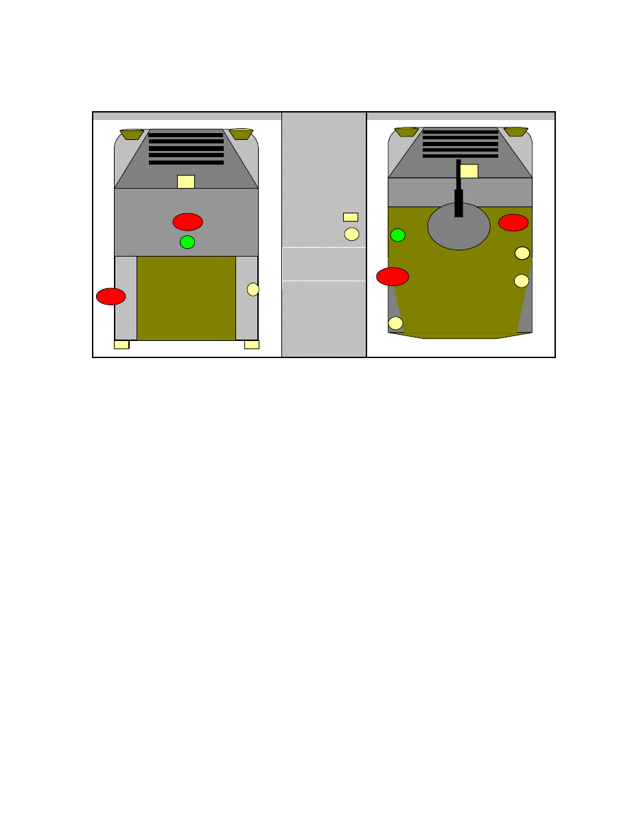
Figure 1. (U) Antenna Locations
2.1.3.1.3 (S) EPLRS/FBCB2.
The network was operated with the EPLRS radio programmed
to use all available channels. Channels whose frequencies would conflict with those used by the
IED jammers were not removed. Transmitter power levels were set to 20 W. End-to-end message
quality was determined counting the number of messages accepted by the receive end (tail)
FBCB2. The lead end FBCB2 was used to create and send 50 free-text messages via the EPLRS
radio link to the tail site. No IED jammers were turned on during this scenario portion.
2.1.3.1.4 (S) Motorola XTS 3000 Handheld Radio.
Test personnel operated the radio in
peer-to-peer LOS mode and used 416.300 MHz as the RF link frequency for this test. End-to-end
message quality was subjectively determined by counting the number of received voice messages
of usable and understandable quality. Test personnel sitting in the lead HMMWV’s passenger
seat transmitted 20 voice messages to other test personnel sitting in the tail HMMWV’s
passenger seat. No IED jammers were turned on during this scenario portion.
2.1.3.1.5 (S) Garmin RINO FRS/GMRS Handheld Radio.
Test personnel used one of the
RINO’s GMRS channels (462.550 MHz) for this test, so that the radio would use its highest
transmit power setting of 1 W. End-to-end message quality was subjectively determined by
counting the number of received voice messages of usable and understandable quality. The
RINO radio was not capable of communicating over the 2-km convoy link with personnel sitting
in the HMMWV passenger seats. A third HMMWV was used to create a 400-meter RF link to
the lead vehicle at the convoy head site. Test personnel sitting in the passenger seat of the third
HMMWV transmitted 20 voice messages in the reverse direction to other test personnel sitting in
SINCGARS
V
EPLRS
E
BFT
B
PLGR
P
FIXED POS
FIXED POS
B
B
V
E
R-M
R-M
SWAPPED
G
G
P
R-L
WARLOCK-R Low Band
R-M
WARLOCK-R Midband
G
WARLOCK-G
R-L
V
E
P
R-L

SECRET//REL TO USA, AUS, CAN, GBR, AND NZL//X1
SECRET//REL TO USA, AUS, CAN, GBR, AND NZL//X1
2-3
the lead HMMWV’s passenger seat at the convoy head site. No IED jammers were turned on
during this scenario portion.
2.1.3.2 (S) Baseline Link with IED Countermeasures Co-located in Same Vehicle.
In this scenario, the IED jammers and communications equipment were installed in the same
vehicle. Each of the preceding baseline performance tests was repeated while the IED jammers
were turned on, one at a time. Only one IED jammer was operational at any time.
2.1.3.3 (S) Baseline Link with IED Countermeasures Located In Different Vehicle.
This scenario was an excursion to evaluate a mitigation method to lessen the Blue Force
communications degradation caused by operating the IED jammers. In this scenario, the jammers
were placed in a separate vehicle and stood off some distance from the victim vehicle containing
the Blue Force communications equipment. The intent was to allow communications across the
2-km-long convoy while keeping the communications vehicle within the protection zone
provided by a nearby IED jammer in a different vehicle. Standoff distances of 50 meters and 100
meters were chosen because they corresponded to postulated convoy vehicle intervals. After
moving the IED jammer to another vehicle, each of the preceding baseline performance tests was
repeated while the IED jammers were turned on, one at a time. Only one IED jammer was
operational at any time.
2.1.3.4 (S) Shortened Link with IED Countermeasures Co-located in Same
Vehicle.
Again, this scenario was an excursion to evaluate a mitigation method to lessen the
Blue Force communications degradation caused by operating the IED jammers. In this scenario,
the jammers and communications equipment were within the same vehicle. The intent was to
determine whether communications could be relayed over a series of short (less loss) RF links
within the 2-km-long convoy. The role of the HMMWV playing the lead vehicle was changed to
that of one located within the body of the convoy, to support message relay capability. Test
personnel moved the hardtop HMMWV (M1026) to successively closer distances to the tail
HMMWV until they could establish reliable communications on the communications system
being tested. After moving the vehicle to a usable distance, each of the preceding baseline
performance tests was repeated while the IED jammers were turned on, one at a time. Only one
IED jammer was operational at any time.
2.1.4 (U) Test Findings
2.1.4.1 (S) Baseline Link with IED Countermeasures Co-located in Same Vehicle
2.1.4.1.1 (S) SINCGARS.
No communications across the 2-km convoy radio link were
possible when the WARLOCK-Red was operating within the same vehicle. The WARLOCK-
Green did not prevent usable communications.
2.1.4.1.2 (S) EPLRS/FBCB2.
No communications across the 2-km convoy radio link were
possible when the WARLOCK-Red was operating within the same vehicle. The WARLOCK-
Green did not prevent usable communications.

SECRET//REL TO USA, AUS, CAN, GBR, AND NZL//X1
SECRET//REL TO USA, AUS, CAN, GBR, AND NZL//X1
2-4
2.1.4.1.3 (S) Motorola XTS 3000 Handheld Radio.
No communications across the 2-km
convoy radio link were possible when either of the two IED jammers was operating within the
same vehicle.
2.1.4.1.4 (S) Garmin RINO FRS/GMRS Handheld Radio.
No communications across a
400-meter intraconvoy radio link were possible when the WARLOCK-Red was operating within
the same vehicle. The WARLOCK-Green did not prevent usable communications.
2.1.4.1.5 (S) Additional Information.
Use of the WARLOCK-Red on the M1026
HMMWV caused the GPS PLGR figure of merit (FOM) to degrade to a “9,” thereby preventing
the FBCB2 from sending an accurate position update. The GPS PLGR installed in the softtop
HMMWV (M1035) was not affected by operation of the WARLOCK-Red or WARLOCK-
Green.
2.1.4.2 (S) Baseline Link with IED Countermeasures Located in Different Vehicle
2.1.4.2.1 (S) SINCGARS.
Using a 50-meter standoff distance between the communications
vehicle and the IED jammer vehicle allowed usable communications when the WARLOCK-Red
was operated in the jammer vehicle.
2.1.4.2.2 (S) EPLRS/FBCB2.
Using a 50-meter standoff distance between the communica-
tions vehicle and the IED jammer vehicle allowed usable communications when the
WARLOCK-Red was operated in the jammer vehicle.
2.1.4.2.3 (U) Motorola XTS 3000 Handheld Radio.
No results are available. This test was
omitted due to lack of available time.
2.1.4.2.4 (U) Garmin RINO FRS/GMRS Handheld Radio.
No results are available. This
test was canceled due to radio hardware failure.
2.1.4.3 (S) Shortened Link with IED Countermeasures Co-located in Same Vehicle
2.1.4.3.1 (S) SINCGARS.
Communications were possible once the radio link was shortened
to 250 meters when the WARLOCK-Red was operated within the same vehicle.
2.1.4.3.2 (S) EPLRS/FBCB2.
Communications were possible once the radio link was
shortened to 400 meters when the WARLOCK-Red was operated within the same vehicle.
2.1.4.3.3 (S) Motorola XTS 3000 Handheld Radio.
The radio link distance for usable
communication when operating a WARLOCK-Red within the same vehicle was not determined.
Further investigation was canceled due to lack of available time.
2.1.4.3.4 (U) Garmin RINO FRS/GMRS Handheld Radio.
No results are available. This
test was canceled due to radio hardware failure.

SECRET//REL TO USA, AUS, CAN, GBR, AND NZL//X1
SECRET//REL TO USA, AUS, CAN, GBR, AND NZL//X1
2-5
2.1.5 (U) Technical Analysis
2.1.5.1 (S) General discussion.
The major element affecting usable communications is the
signal-to-noise ratio (S/N) at the radio receiver. Raising the S/N increases receiver performance,
lowering it degrades performance. The ratio can be increased by raising the desired signal
strength or by lowering the undesirable noise presented to the receiver’s antenna. Shortening the
radio link in the preceding shortened link excursion reduces the RF path loss of the desired
signal, hence increases its strength at the receiver antenna. Standing off the IED jammer
decreases the undesired noise presented to the receiver antenna.
2.1.5.2 (S) SINCGARS.
At least three methods are readily available to allow usable com-
munications via SINCGARS within the convoy scenario.
a. (S) Frequency Coordination and Hopset Tailoring. The first, which was not explored
in this time-constrained test, is frequency coordination and SINCGARS hopset tailoring around
IED jammer frequencies. After reviewing the in-country hopset, there appears to be sufficient RF
spectrum available to trade off frequencies for jammer use. One potential problem will be the RF
spectral purity and spurious signals and harmonics generated by the jammers in addition to their
intended transmit frequencies. This could be resolved by trading off more SINCGARS
frequencies and/or cleaning up the jammer signals via better internal filters or commercial off-
the-shelf (COTS) external filters. Another potential problem could be chaos within the
SINCGARS networks if there are continuous changes to the SINCGARS hopsets and their
distribution is not timely and thorough throughout the affected units.
b. (S) Jammer Standoff. Easily implemented if the jammers can protect multiple vehicles.
c. (S) Radio Repeater over Shortened Radio Links. This is probably the least desirable due
to the increased hardware requirements, radios and antennas. Manual operator message relay
could also be employed but would be labor intensive and prone to error. Operation at RF power
amplifier power (50 W) could increase the link distance and reduce hardware requirements.
2.1.5.3 (S) EPLRS/FBCB2.
Again, at least three methods are readily available to allow
usable communications via EPLRS/FBCB2 within the convoy scenario.
a. (S) Frequency Coordination and EPLRS Channel Tailoring. The principles discussed in
the preceding SINCGARS method are applicable.
b. (S) Jammer Standoff. Easily implemented if the jammers can protect multiple vehicles.
c. (S) Radio Repeater over Shortened Links. This option is more desirable for EPLRS
because every EPLRS within the network automatically functions as a repeater. Additionally, the
usable link distance is greater—400 meters. Only five EPLRS in a 2-km-long convoy would be
required to provide end-to-end data communications. Positional data and SA would be supported
as long as PLGR is working properly (not a FOM 9). Voice communications are not supported.
2.1.5.4 (S) Motorola XTS 3000 Handheld Radio.
Frequency coordination and using a
channel whose frequency is outside the jammer’s band are the only readily available recom-
mendations.

SECRET//REL TO USA, AUS, CAN, GBR, AND NZL//X1
SECRET//REL TO USA, AUS, CAN, GBR, AND NZL//X1
2-6
2.1.5.5 (S) Garmin RINO FRS/GMRS Handheld Radio.
Frequency coordination and
using a channel whose frequency is outside the jammer’s band are the only readily available
recommendations.
2.1.5.6
(S)
Additional Information Regarding GPS PLGR.
Given the limited
observation data available, the most readily available method for preventing GPS position
degradation is separation between the GPS and jammer antennas. This is the most likely
explanation of why the GPS was affected only on the hardtop HMMWV (M1026) installation.
The antennas on the softtop HMMWV (M1035) installation were farther apart and the GPS
antenna was somewhat shielded from the jammer antennas by the rear panel of the ASK.

SECRET//REL TO USA, AUS, CAN, GBR, AND NZL//X1
SECRET//REL TO USA, AUS, CAN, GBR, AND NZL//X1
2-7
2.2 (S) IED COUNTERMEASURES IMPACT ON BASE-TO-CONVOY COMMUNI-
CATIONS
2.2.1 (S) Objective.
The objective was to determine whether operating IED jammer systems
(WARLOCK-Red, WARLOCK-Green) degraded Blue Force communications. Additional
objectives were to determine mitigation techniques that allow simultaneous operations when
both types of systems were co-located.
2.2.2 (S) Criteria.
Simultaneous operation of co-located IED jammers and Blue Force com-
munications equipment.
2.2.3 (S) Test Procedures.
Test personnel postulated that one of the most likely com-
munications scenarios would be communications between a headquarters element, or base site,
and an element within the convoy. The Blue Force was expected to have SINCGARS,
EPLRS/FBCB2, BFT/FBCB2, and SPITFIRE (satellite mode) available for base-to-convoy
communications. A LOS terrestrial radio link to the convoy of 20 km for SINCGARS and
EPLRS was postulated, based on previous testing at USAEPG on SINCGARS and EPLRS radio
networks. Additionally, it was postulated that jammers would be installed only in vehicles within
the convoy, not at any base site. The BFT/FBCB2 and SPITFIRE systems use satellite RF links
rather than LOS terrestrial RF links. A real satellite link was available for the BFT/FBCB2
scenario. Testing for SPITFIRE scenarios used LOS terrestrial link, manipulated to simulate a
satellite down link.
2.2.3.1 (U) Baseline Link Configuration
2.2.3.1.1 (S) General.
The HMMWVs from the previous intraconvoy test scenarios and a
USAEPG Joint Tactical Radio System (JTRS) test trailer were used to construct the various radio
links. The hardtop HMMWV (M1026) and a USAEPG JTRS test trailer played the role of the
base site. The softtop HMMWV (M1035) played the role of a convoy element and remained at
the test site previously used by the tail vehicle in the intraconvoy scenarios. The base site and
convoy elements were sited 4 km from each other at the YPG test area. Voice and data messages
were sent from the base site to the convoy element. Reverse message traffic was not sent because
the IED jammers were located only within the convoy.
2.2.3.1.2 (S) SINCGARS.
The network was operated using a 1,000-frequency hopset
structurally similar to the one used in Iraq operations. Frequencies conflicting with those used by
the IED jammers were not removed from the hopset. The base site SINCGARS transmitted out
of the JTRS test trailer using a 10-meter-high OE-254 antenna set. The base site SINCGARS
transmit power levels were set to high power (4.5 W), then further attenuated to provide a
received signal level (RSL) of -85 decibels referenced to 1 milliwatt (dBm) at the receiving
convoy element site. The RSL was derived from experience in past SINCGARS testing. The
convoy element vehicle was configured as in the previous intraconvoy scenarios. Antenna
placements remained the same as depicted in figure 1. Probability of radio link synchronization
was measured by sending 10 short data messages and manually counting the receptions. End-to-
end message quality was determined by measuring the BER of these 10 short data messages.

SECRET//REL TO USA, AUS, CAN, GBR, AND NZL//X1
SECRET//REL TO USA, AUS, CAN, GBR, AND NZL//X1
2-8
BERs of 8 percent or less indicate that usable voice or data message operations are possible. No
IED jammers were turned on during this scenario portion.
2.2.3.1.3 (S) EPLRS/FBCB2.
The network was operated with the EPLRS radio programmed
to use all available channels. Channels whose frequencies would conflict with those used by the
IED jammers were not removed. The base site EPLRS transmitted out of the JTRS test trailer
using an AS 3449 EPLRS vehicular antenna mounted to the mast on the trailer. The base site
EPLRS transmit power levels were set to 3 W to provide an RSL that replicated those from a
distant unit. Manually inserted attenuation could not be used because the EPLRS detects it as an
antenna fault and sets its transmit power to the lowest level, which would not have provided a
viable test link. End-to-end message quality was determined by counting the number of messages
accepted by the receive end (convoy element) FBCB2. The base site FBCB2 was used to create
and send 50 free-text messages via the EPLRS radio link to the tail site. No IED jammers were
turned on during this scenario portion.
2.2.3.1.4 (S) BFT/FBCB2.
Testing was conducted at USAEPG as a post-BPC test
effort. USAEPG test personnel installed BFT in each of two softtop command-type HMMWVs
(M1035). One played the role of the distant base station, the other the role of a convoy element.
One WARLOCK-Red was installed in the HMMWVs playing the role of the convoy element
vehicle. WARLOCK-Green was not tested. Real satellite link geometry was used for the
communications RF link. End-to-end message quality was determined by counting the number of
messages accepted by the receive end (convoy element) FBCB2. The base site end FBCB2 was
used to create and send 50 free-text messages via the EPLRS radio link to the convoy element
HMMWV. No IED jammers were turned on during this scenario portion.
2.2.3.1.5 (S) SPITFIRE.
The base site SPITFIRE transmitted out of the hardtop HMMWV
(M1026) but used a Near Term Digital Radio (NTDR) antenna mounted to the side of the JTRS
test trailer. A simulated satellite downlink to the SPITFIRE radio was created by selecting a
frequency in the normal downlink range of 240–270 MHz and attenuating the base site transmit
signal to a -85 dBm RSL at the receiving convoy element site. End-to-end message quality was
subjectively determined by counting the number of received voice messages of usable and
understandable quality. Test personnel at the base site transmitted 20 voice messages to other test
personnel sitting in the convoy element HMMWVs. No IED jammers were turned on during this
scenario portion.
2.2.3.2 (S) Baseline Link with IED Countermeasures Co-located in Same Vehicle.
In this starting scenario, the IED jammers and communications equipment were installed in the
same convoy element vehicle. Each of the preceding baseline performance tests was repeated
while the IED jammers were turned on, one at a time. Only one IED jammer was operational at
any time. The BFT/FBCB2 was omitted due to expired test time.
2.2.3.3 (S) Baseline Link with IED Countermeasures Located in Different Vehicle.
This scenario was an excursion to evaluate a mitigation method to lessen the Blue Force
communications degradation caused by operating the IED jammers. In this scenario, the IED
jammers were placed in a separate vehicle and stood off some distance from the victim vehicle
containing the Blue Force communications equipment. The intent was to allow communications

SECRET//REL TO USA, AUS, CAN, GBR, AND NZL//X1
SECRET//REL TO USA, AUS, CAN, GBR, AND NZL//X1
2-9
at the convoy element vehicle while keeping it within the protection zone provided by a nearby
jammer in a different vehicle. Standoff distances of 50 meters and 100 meters were chosen
because they corresponded to postulated convoy vehicle intervals. After moving the IED jammer
to another vehicle, each of the above baseline performance tests was repeated while the IED
jammers were turned on, one at a time. Only one IED jammer was operational at any time.
2.2.4 (U) Test Findings
2.2.4.1 (S) Baseline Link with IED Countermeasures Co-located in Same Vehicle
2.2.4.1.1 (S) SINCGARS.
No communications across the base-to-convoy radio link were
possible when the WARLOCK-Red was operating within the same vehicle. The WARLOCK-
Green did not prevent usable communications.
2.2.4.1.2 (S) EPLRS/FBCB2.
No communications across the base-to-convoy radio link were
possible when the WARLOCK-Red was operating within the same vehicle. The WARLOCK-
Green did not prevent usable communications.
2.2.4.1.3 (S) BFT/FBCB2.
No communications across the base-to-convoy radio link were
possible when the WARLOCK-Red was operating within the same vehicle. The WARLOCK-
Green effects have not been tested. Testing at YPG was canceled due to time constraints. The
results presented here are from follow-on testing conducted at USAEPG.
2.2.4.1.4 (S) SPITFIRE.
Communications across the base-to-convoy radio link were not
affected by operation of either of the IED jammers.
2.2.4.2 (S) Baseline Link with IED Countermeasures Located in Different Vehicle
2.2.4.2.1 (S) SINCGARS.
Using a 50-meter standoff distance between the communications
vehicle and the IED jammer vehicle allowed usable communications when the WARLOCK-Red
was operated in the jammer vehicle.
2.2.4.2.2 (S) EPLRS/FBCB2.
Using a 50-meter standoff distance between the communi-
cations vehicle and the IED jammer vehicle allowed usable communications when the
WARLOCK-Red was operated in the jammer vehicle.
2.2.4.2.3 (S) BFT/FBCB2.
Using a 50-meter standoff distance between the communications
vehicle and the IED jammer vehicle allowed usable communications when the WARLOCK-Red
was operated in the jammer vehicle. The WARLOCK-Green mitigation methods have not been
tested. Testing at YPG was canceled due to time constraints. The results presented here are from
follow-on testing conducted at USAEPG.
2.2.4.2.4 (S) SPITFIRE.
No standoff testing required. Communications across the base-to-
convoy radio link were not affected by operation of either of the IED jammers.

SECRET//REL TO USA, AUS, CAN, GBR, AND NZL//X1
SECRET//REL TO USA, AUS, CAN, GBR, AND NZL//X1
2-10
2.2.5 (U) Technical Analysis
2.2.5.1 (S) General Discussion.
The major element affecting usable communications is the
S/N at the radio receiver. Raising the S/N increases receiver performance, lowering it degrades
performance. The ratio can be increased by raising the desired signal strength or by lowering the
undesirable noise presented to the receiver’s antenna. The only available option to increase the
S/N in this scenario was standing off the IED jammer to decrease the undesired noise presented
to the receiver antenna.
2.2.5.2 (S) SINCGARS.
At least two methods are readily available to allow usable com-
munications via SINCGARS within the convoy scenario.
a. (S) Frequency Coordination and Hopset Tailoring. The first, which was not explored
in this time-constrained test, is frequency coordination and SINCGARS hopset tailoring around
IED jammer frequencies. After reviewing the in-country hopset, there appears to be sufficient RF
spectrum available to trade off frequencies for jammer use. One potential problem will be the RF
spectral purity and spurious signals and harmonics generated by the jammers in addition to their
intended transmit frequencies. This could be resolved by trading off more SINCGARS
frequencies and/or cleaning up the jammer signals via better internal filters or COTS external
filters. Another potential problem could be chaos within the SINCGARS networks if there are
continuous changes to the SINCGARS hopsets and their distribution is not timely and thorough
throughout the affected units.
b. (S) Jammer standoff. Easily implemented if the jammers can protect multiple vehicles.
2.2.5.3 (S) EPLRS/FBCB2.
Again, at least two methods are readily available to allow usable
communications via EPLRS/FBCB2 within the convoy scenario.
a. (S) Frequency Coordination and EPLRS Channel Tailoring. The principles discussed in
the above SINCGARS method are applicable.
b. (S) Jammer Standoff. Easily implemented if the jammers can protect multiple vehicles.
2.2.5.4 (S) BFT/FBCB2.
The WAROCK-Red was not expected to impact BFT operation,
since the BFT receives at much higher frequencies than the WARLOCK-Red transmit
frequencies. Additional test excursions show that BFT degradation occurs only when both the
low band and midband units are transmitting. Operation of only one-half of the WARLOCK-Red
system does not impact BFT communications. Possibilities are that—
a. (S) Combined WARLOCK-Red unwanted spurious emissions have sufficient band-
width to impact BFT.
b. (S) Combined WARLOCK-Red transmitter energy overloads the BFT receiver.
c. (S) Combined WARLOCK-Red transmitter energy causes intermodulation products
within the active component of the BFT system.

SECRET//REL TO USA, AUS, CAN, GBR, AND NZL//X1
SECRET//REL TO USA, AUS, CAN, GBR, AND NZL//X1
2-11
Further testing exploring add-on low pass filtering and antenna separation options should be
conducted. Until then, jammer standoff appears to be the only viable mitigation technique,
assuming that the WARLOCK-Red can protect multiple vehicles.
2.2.5.5 (S) SPITFIRE.
Use frequency coordination if an EMC should occur in the near future.

UNCLASSIFIED
UNCLASSIFIED
2-12
INTENTIONALLY BLANK

UNCLASSIFIED
UNCLASSIFIED
3-1
SECTION 3. APPENDICES (U)

UNCLASSIFIED
UNCLASSIFIED
3-2
INTENTIONALLY BLANK

UNCLASSIFIED
UNCLASSIFIED
A-1
APPENDIX A. ABBREVIATIONS (U)
AM amplitude
modulation
ASK
armored survivability kit
BER bit
error
rate
BFT Blue
Force
Tracking
COMSEC communications
security
COTS commercial
off-the-shelf
C
2
command and control
DAMA
demand assigned multiple access
dBm
decibels referenced to 1 milliwatt
DTC
(US Army) Developmental Test Command
EMC electromagnetic
compatibility
EMUT
Enhanced Manpack Ultrahigh Frequency Terminal
EPLRS
Enhanced Position Location Reporting System
FBCB2
Force XXI Battle Command Brigade and Below
FH frequency
hopping
FM frequency
modulation
FOM figure
of
merit
FRS
Family Radio Service
GMRS
General Mobile Radio Service
GPS
Global Positioning System
HMMWV
high mobility, multipurpose, wheeled vehicle
JTRS
Joint Tactical Radio System
km kilometer
LOS
line of sight
MBMMR Multiband
Multimission
Radio

UNCLASSIFIED
UNCLASSIFIED
A-2
MCR
message completion rate
MHz megahertz
NTDR
Near Term Digital Radio
PLGR
Precision Lightweight Global Positioning System Receiver
RF radio
frequency
RSL
received signal level
SATCOM satellite
communications
SA situational
awareness
SC single
channel
SINCGARS
Single Channel Ground and Airborne Radio System
S/N signal-to-noise
ratio
TOC tactical
operations
center
TRMS
Test Resource Management System
UHF ultrahigh
frequency
USAEPG
US Army Electronic Proving Ground
VHF
very high frequency
W watt

UNCLASSIFIED
UNCLASSIFIED
B-1
APPENDIX B. DISTRIBUTION LIST (U)
Agency
Copies
PROGRAM MANAGER SIGNALS WARFARE
ATTN SFAE IEW&S SG LTC JOHN MASTERSON
296 SHERRILL AVENUE
FORT MONMOUTH NJ 07703
1
YUMA TEST CENTER
ATTN CSTE DTC YP YT AC EA MS MARY BETH WEAVER
301 C ST
YUMA AZ 85365-9498
1
DEVELOPMENTAL TEST COMMAND
ATTN CSTE DTC CS COL JOHN ROONEY
BLDG 314 ROOM 208
ABERDEEN PROVING GROUND MD 21005-5055
1

UNCLASSIFIED
UNCLASSIFIED
B-2
INTENTIONALLY BLANK


SECRET//REL TO USA, AUS, CAN, GBR, AND NZL//X1
SECRET//REL TO USA, AUS, CAN, GBR, AND NZL//X1
Wyszukiwarka
Podobne podstrony:
blue force comms emc warlock test results 2 2004
informatyka test wiedzy 2004
test MP 7-8 2004, medycyna, Testy do egzaminu z chorób wewnętrznych, Testy MP
Test z Interny z 2004, Test z Interny z 2004-06-02
test chirurgia 2004, ###Chirurgia materiały
test MP 5 2004, medycyna, Testy do egzaminu z chorób wewnętrznych, Testy MP
DESIGN, SIMULATION, AND TEST RESULTS OF A HEAT ASSISTED THREE CYLINDER STIRLING HEAT PUMP (C 3)(1)
test MP 4 2004, medycyna, Testy do egzaminu z chorób wewnętrznych, Testy MP
Test Emotogenny 2004-2005 uksw DZIENNE gr b, ćwiczenia
large scale+fragment+impact+sensitivity+test+results+of+a+melt+castable%2c+general+purpose%2c+insens
test MP 6 2004, medycyna, Testy do egzaminu z chorób wewnętrznych, Testy MP
test MP 9 2004, medycyna, Testy do egzaminu z chorób wewnętrznych, Testy MP
testy egzaminacyjne z anatomii, test ręka L 2004, 1) Do musculi hypothenari NIE NALEŻY:
test MP 3 2004, medycyna, Testy do egzaminu z chorób wewnętrznych, Testy MP
test 3b - 2004, Biologia - testy liceum
Interna2004, TEST Z INTERNY Z 2004-06-02
informatyka test wiedzy 2004
więcej podobnych podstron