
Chapter 13
Supplement: Revisions and information on later models
Contents
Introduction
1. Specifications
2. Fuel, emission control and exhaust systems. Checking and adjusting throttle switch (turbo
models)
3. Ignition and starting systems
Ignition system — overview
TCI-H ignition system
Ignition coil — checking
Hall control unit — checking
Hall transmitter — checking
EIS control unit — checking
Flywheel sensor (Digital Ignition Timing Control system) — checking
Flywheel sensor (Digital Ignition Timing Control system — removal and
installation
Distributor — removal and installation
Ignition retard — checking
Timing control unit — removal and installation
4. Transmission and transaxle
Shift linkage — adjusting
Introduction
This Supplement contains specifications and service procedure changes that apply to Porsche 924
models produced for the 1981 and 1982 model years. Also included is information related to
previous models that was not available at the time of the original publication of this manual. Where
no differences (or very minor differences) exist between the 1981 and 1982 models and previous
models, no information is given. in such instances, the original material included in Chapters 1
through 12 should be used.
1 Specifications
Note: The specifications listed here include only those items which differ from those listed in
Chapters 1 through 12. For information not specifically listed here, refer to the appropriate Chapter.
Fuel. emission control and exhaust systems
Idling speed
Manual transmission
750 to 800 rpm
Automatic transmission
1000± 50 rpm
Leak test
Minimum pressure after 10 minutes
2.0 bar
Minimum pressure after 20 minutes
1.7 bar
Fuel pump delivery rate
750 cc per 30 seconds

Spark plug type
2 Fuel, emission control and exhaust systems Checking and adjusting throttle switch (turbo
models)
Checking
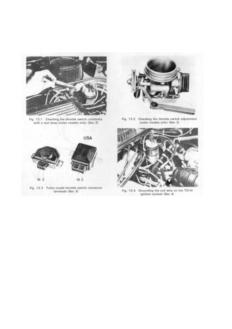
1 Connect a test lamp between the battery and the white/blue wire on the multiple pin plug as shown
in the accompanying illustration.
2 The lamp should light. Move the throttle slowly by hand and make sure the lamp goes out at about
1 °. This can be checked with a 0.2 to 0.5 mm feeler gauge at the stop screw as shown in the
illustration.
Adjusting
3 Remove the throttle housing and loosen the mounting screw on the switch.
4 Insert a 0.3 mm feeler gauge between the stop screw and throttle stop and connect a test lamp
between terminals 2 and 18. 5 Turn the switch until it just opens and the test lamp goes out. Tighten
the screw.
6 Repeat the test and install the throttle housing.
'Warm' control pressure
3.4 to 5.2 bar
'Cold' control pressure
2.2 ± 0.20 bar at 68°F (20°C)
Injection vaive opening pressure
2.5 to 3.6 bar
System pressure (test value)
4.5 to 5.2 bar
Ignition and starting systems
Ignition timing
Non-turbo
0° ± 1 ° at 650 to 800 rpm
Turbo
6° to 10° BTDC at 900 rpm
Non-turbo
Bosch
WR 6 DS
Beru
RS 37
Turbo
Bosch
WR 6 DS
Champion
N 7 GY
Spark plug gap
Non-turbo
0.028 in (0.7 mm)
Turbo
Bosch
0.028 in(0.7 mm)
Champion
0.024 in (0.6 mm)
Ignition coil type
Non-turbo
Bosch 211 905 115B without
resistor wire
Turbo
Bosch 211 905 115B
Non-turbo Electronic Ignition
Stabilization (EISI unit)
Bosch 211 .905 351
Distributor type Non-turbo
Bosch 477 905 203
Turbo
Bosch 931 602 141 00
Non-turbo idle stabilization control unit Bosch 477 906 083
Turbo control unit
Bosch 931 602 073 00
3 Ignition and starting systems
Ignition system — overview
1 These models are equipped with a different type of ignition system. While the distributor and some
components differ from earlier models, many checking and adjustment procedures are unchanged.
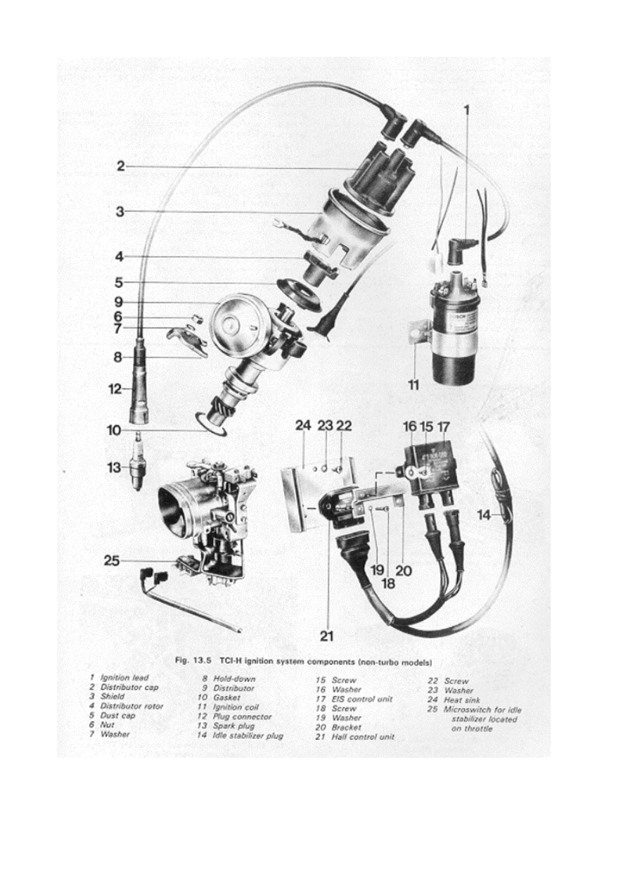
2 Non-turbo engines are equipped with a TCI-H ignition system, while turbo engines are equipped
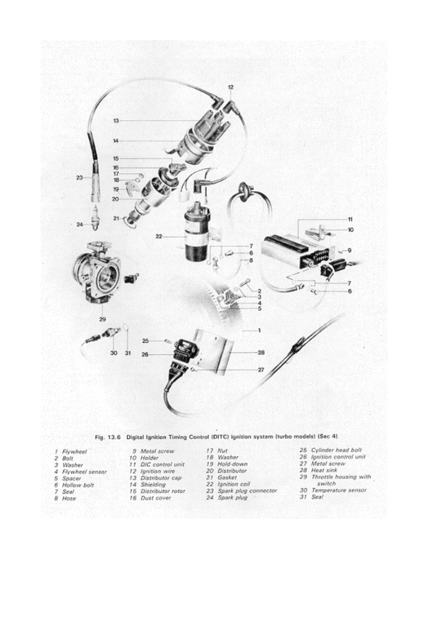
with a Digital Ignition Timing Control System (DITC)
TCI-H ignition system
3 The TCI-H system uses a Hall transmitter and idle stabilizer in place of the induction transmitter
on earlier models. To avoid damage to the system, the following precautions must be observed: The
ignition should be Off when testers or leads are connected or disconnected. The distributor cap and
dust cap spring retainers must not be allow-ed to hang down into the sensor system when the engine
is being cranked. A capacitor should never be connected to the coil. The ignition coil must, be
replaced with a coil of the same specification. Whenever the engine is cranked over without starting
it, connect the coil wire to ground as shown in the illustration or unplug the Hall control unit.
Starting voltage should never exceed 16 volts. Because the EIS control unit Will affect idle speed,
the unit must be disconnected during testing and adjustments. This is accomplished by detaching the
plug located on the left wheel well housing in the engine compartment.
Ignition coil — checking
4 Disconnect the coil wires and remove the cap. Inspect the top of the coil to make sure the plug is
secure and that no sealing compound is leaking. Replace the coil with a new one if the plug is
damaged or missing
5 Measure the resistance between terminal 1 and terminal 15. The resistance should be 0.52 to 0.76

ohms
6 Measure the resistance between terminal 1 and terminal 4. The resistance should be 2.4 to 3.5 K-
ohms.
7 Replace the ignition coil with a new one if the resistance is not within the specifications.
Hall control unit — checking
8 Disconnect the idle stabilizer plug.
9 Ground the ignition coit as described in the precautions in Paragraph 3.
10 Unplug the Hall transmitter at the distributor.
11 Connect a voltmeter to ignition coil terminals 15 and 1 and turn the ignition on. The voltmeter
should indicate between 5 and 6 volts, then after about 1 second, it should drop to 0.
12 With the voltmeter connected as described in Paragraph 11, momen- tarily connect a wire
between the green (center) terminal of the Hall transitter plug and a good ground. The voltage should
rise and then drop to 0.
13 Measure the voltage between the outside terminals of the plug with the ignition on and make sure
the reading is at least 10 volts.
14 Replace the control unit with a new one if it fails any of the tests.
Hall transmitter — Checking
15 With the ignition coil grounded, connect a test lamp between terminals 1 and 15.
16 When the starter is operated, the test lamp should flicker. If it does not, the Hall transmitter is
defective and must be replaced with a new one.
EIS control unit — checking
17 Inspect the control unit and plugs for proper connection, corrosion, bent connectors and damaged
O-rings.
18 With the engine at normal operating temperature, disconnect the idle stabilizer plug.
19 Set the idle speed at approximately 700 rpm and then plug in the idle stabilizer. The engine speed
should rise to around 800 rpm, indicating that the EIS has moved the ignition timing control in the
advance direction [which means it is operating properly).
20 Disconnect the stabilizer plug and adjust the idle speed to between 750 and 800 rpm. Connect the
stabilizer plug.
21 Replace the EIS control unit if it fails the test.
Flywheel sensor (Digital Ignition Timing Control system) — checking
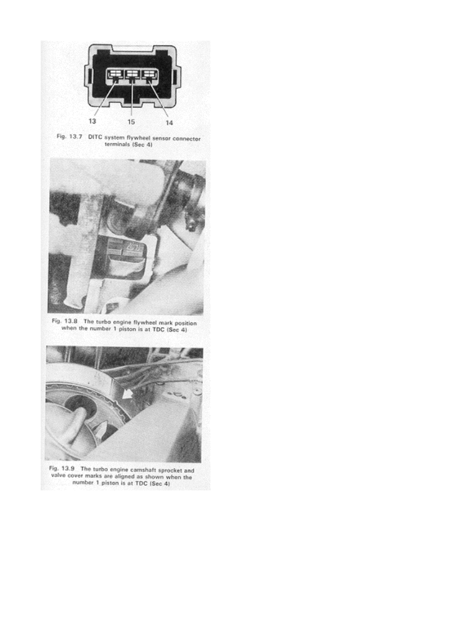
22 Unplug the flywheel sensor plug at the control unit.
23 Use a test lamp to check for continuity between terminals 13 and 15, followed by terminals 14
and 15 of the sensor plug.
24 Replace the sensor with a new one if it fails either continuity test.
Flywheel sensor (Digital Ignition Timing Control system) — removal and instaifation
Removal
25 Remove the ignition mark cover.
26 Remove the flywheel sensor mounting bolt and pull out the sensor and spacers (if equipped).
27 Remove the hollow bolts on the intake air distributor and timing control unit and disconnect the
flywheel sensor plug.
28 Remove the sensor, grommet and hose. Remove the clamp to separate the hose from the
grommet.
Installation
29 Push the hose into the grommet and secure it with a new clamp.
30 Push the lines into the passenger compartment and install the grom met, making sure it fits
tightly. It may be necessary to use body sealant.
31 Install the flywheel sensor and spacers (if equipped), tightening the bolt to 6 ft-lb (8 Nm).
32 Connect the hose to the air distributor and timing control unit, making sure the seals are not
damaged. Route the hose in such a way that there are no sharp bends and tighten the hollow bolt to 7
Ft-lb (9 Nm).
Distributor — removal and instaifation
33 Position the number 1 piston at TDC with the mark on the flywheel aligned with the edge of the
bellhousing and the marks on the cam shaft sprocket and valve cover aligned as shown in the
illustrations.
34 Remove the distributor cap and disconnect the ground wire at the shielding.
35 Remove the hold-down nut and withdraw the distributor from the engine.
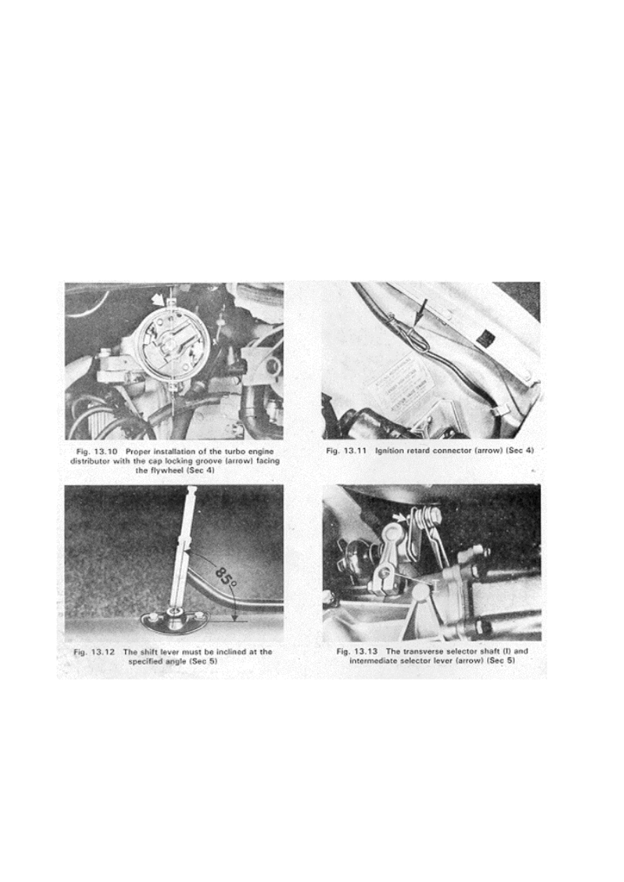
36 Install the gasket on the distributor flange.
37 Insert the distributor carefully into the engine so that the cap locking groove is facing the flywheel
and the mounting clips face the vehicle longitudinal axis and install the rotor as shown in the
illustration.
38 Install the distributor cap.
39 Install the hold-down nut and tighten it securely.
Ignition retard — checking
40 Connect a timing tight to the engine. 4T. Start the engine, rev it up to approximately 1500 rpm
and note the ignition liming. Shut the engine off.
42 Unplug the ignition retard connector shown in the accompanying illustration.
43 Start the engine and check that the timing is now retarded by about 7°.
44 If the ignition timing is not retarded the specified amount there is a fault in the wiring or timing
control unit.
Timing control unit — removal and installation Removal
45 Unplug the multiple pin connector on the timing control unit and remove the hollow bolt from the
hose.
46 Remove the bolts on the holder and withdraw the control unit toward the footwell. Installation
47 Push the timing control unit into place and tighten the bolts securely.
48 Carefully plug in the connector and install the hollow bolt. Tighten the bolt to 7 Ft-lb (9 mm).
4 Transmission and transaxle
Shift linkage — adjusting
1 With the transmission in Neutral, the intermediate selector lever can only be installed with one
inclination as it is the only way it will fit on the shaft due to the changed design.
2 Move the base of the selector lever to adjust it to an angle of 85° as shown in the illustration.
3 With the selector lever in Neutral, the transverse selector shaft I shown in the illustration will be
held in the middle (3rd and 4th gear) by spring pressure. When correctly adjusted, the shift lever
should not lean to the side. Adjustment is made at the intermediate selector lever.

Wyszukiwarka
Podobne podstrony:
Frysztacki, konspekt z rozdziałów 13 16
15. Rozdzial 13
Rozdział 13, Dni Mroku 1 - Nocny wędrowiec
16 10 13 Psychologia
Badanie płytą 16 05 13 MC 20 ( rondo 1 w wa)
16 rozdzial 15 EJCDLTJY3F3I2FKL Nieznany (2)
14 rozdzial 13 w2pa42u4da5r3dcm Nieznany (2)
16 rozdzial 15 zpgg3d2etikxyjv3 Nieznany
16(2), Rozdzial drugi
16(3), ROZDZIA˙ SZESNASTY
18. Rozdzial 16, Rozdział XVI
007, p2, ROZDZIAŁ 13 : POD ZNAKIEM BOGÓW
Teoria egzamin 16.09, 13-16, Zadanie 13
Rozdział-13-Motoszybowce, Szkolenie Szybowcowe, Procedury operacyjne
13 rozdzial 13 NSBB2L5SXN4GTHOI Nieznany (2)
rozdzial 13, Zimbardo ksiazka i streszcznie
Lauferowie rozdziały 9 13
więcej podobnych podstron