
User Information
1
2
Installing and Removing the
FM 352
3
Wiring the FM 352 Electronic
Cam Controller
4
5
6
Putting the FM 352 into Operation
7
Reference Information
8
9
10
11
12
Appendices
A
B
C
02/2000
C79000-G7076-C352
Edition 04
FM 352 Electronic Cam
Controller
Installation and Parameter
Assignment
Manual
This manual is part of the documentation package
with the order number:
6ES7352-1AH00-8BG0
SIMATIC

This manual contains notices which you should observe to ensure your own personal safety, as
well as to protect the product and connected equipment. These notices are highlighted in the
manual by a warning triangle and are marked as follows according to the level of danger:
!
Danger
indicates that death, severe personal injury or substantial property damage will result if proper
precautions are not taken.
!
Warning
indicates that death, severe personal injury or substantial property damage can result if proper
precautions are not taken.
!
Caution
indicates that minor personal injury or property damage can result if proper precautions are not
taken.
Note
draws your attention to particularly important information on the product, handling the product,
or to a particular part of the documentation.
Only qualified personnel should be allowed to install and work on this equipment. Qualified
persons are defined as persons who are authorized to commission, to ground, and to tag circuits,
equipment, and systems in accordance with established safety practices and standards.
Note the following:
!
Warning
This device and its components may only be used for the applications described in the catalog or
the technical description, and only in connection with devices or components from other
manufacturers which have been approved or recommended by Siemens.
This product can only function correctly and safely if it is transported, stored, set up, and
installed correctly, and operated and maintained as recommended.
SIMATIC
, SIMATIC NET
and SIMATIC HMI
are registered trademarks of
SIEMENS AG.
Third parties using for their own purposes any other names in this document which refer to trade-
marks might infringe upon the rights of the trademark owners.
We have checked the contents of this manual for agreement with the
hardware and software described. Since deviations cannot be pre-
cluded entirely, we cannot guarantee full agreement. However, the
data in this manual are reviewed regularly and any necessary cor-
rections included in subsequent editions. Suggestions for improve-
ment are welcomed.
Disclaimer of Liability
Copyright
Siemens AG 1996 All rights reserved
The reproduction, transmission or use of this document or its
contents is not permitted without express written authority.
Offenders will be liable for damages. All rights, including rights
created by patent grant or registration of a utility model or design, are
reserved.
Siemens AG
Bereich Automatisierungs- und Antriebstechnik
Geschaeftsgebiet Industrie-Automatisierungssysteme
Postfach 4848, D- 90327 Nuernberg
Siemens AG 1996
Subject to technical change.
Siemens Aktiengesellschaft
C79000-G7076-C352
Notes on Safety
Qualified Personnel
Correct Usage
Trademarks

iii
FM 352 Electronic Cam Controller
C79000-G7076-C352-04
Preface
Validity of the Manual
This manual contains the description of the FM 352 electronic cam controller valid
at the time the manual was printed. We reserve the right to describe modifications
in the functionality of the FM 352 in a product information leaflet.
The manual with the number in the footer ....
is valid for the FM 352 with order number
EWA 4NEB 720 6004-02
6ES7 352-1AH00-0AE0
EWA 4NEB 720 6004-02 a
6ES7 352-1AH01-0AE0
C79000-G7076-C352-03
6ES7 352-1AH01-0AE0
Content of the manual
This manual describes the hardware and software of the FM 352 electronic cam
controller.
It consists of the following:
•
A section describing basic aspects (Chapters 1 to 7)
•
A reference section (Chapters 8 to 12)
•
An appendix (Chapters A, B and C)
•
An index.

Preface
iv
FM 352 Electronic Cam Controller
C79000-G7076-C352-04
Further Support
If you have questions about using the products described in the manual and you
cannot find the answers here, please contact your local Siemens representative.
You will find the addresses, for example, in the appendix ”SIEMENS Worldwide” in
the installation manual
S7-300/M7-300 Programmable Controllers, Hardware and
Installation, CPU Data.
If you have any questions or comments on this manual, please fill out the remarks
form at the end of the manual and return it to the address shown on the form. We
would be grateful if you could take the time to answer the questions giving your
own personal opinion of the manual.
To help you to become familiar with working with SIMATIC S7 PLCs,
we offer a range of courses.
Please contact your regional training center or the central training center in
D-90027 Nuremberg, Tel. +49 911/895-3200 for more information.
CE Mark
Our products meet the requirements of the EU directive 89/336/EEC
”Electromagnetic Compatibility” and the harmonized European standards (EN)
listed in the directive.
in compliance with the above mentioned EU directive, Article 10, the conformity
declarations are available to the relevant authorities at the following address:
Siemens Aktiengesellschaft
Bereich Automatisierungstechnik
A&D AS E48
Postfach 1963
D-92209 Amberg

v
FM 352 Electronic Cam Controller
C79000-G7076-C352-04
Contents
1
Product Overview
. . . . . . . . . . . . . . . . . . . . . . . . . . . . . . . . . . . . . . . . . . . . . . . . . . . . . .
1.1
What is the FM 352?
. . . . . . . . . . . . . . . . . . . . . . . . . . . . . . . . . . . . . . . . . . . . .
1.2
Areas of Application of the FM 352
. . . . . . . . . . . . . . . . . . . . . . . . . . . . . . . .
1.3
Structure of an Electronic Cam Controller with an FM 352
. . . . . . . . . . . .
2
Basics of Cam Control
. . . . . . . . . . . . . . . . . . . . . . . . . . . . . . . . . . . . . . . . . . . . . . . . . .
2.1
Cams
. . . . . . . . . . . . . . . . . . . . . . . . . . . . . . . . . . . . . . . . . . . . . . . . . . . . . . . . . .
2.2
Tracks
. . . . . . . . . . . . . . . . . . . . . . . . . . . . . . . . . . . . . . . . . . . . . . . . . . . . . . . . .
2.2.1
Tracks and Track Result
. . . . . . . . . . . . . . . . . . . . . . . . . . . . . . . . . . . . . . . . . .
2.2.2
Special Tracks
. . . . . . . . . . . . . . . . . . . . . . . . . . . . . . . . . . . . . . . . . . . . . . . . .
2.3
Hysteresis
. . . . . . . . . . . . . . . . . . . . . . . . . . . . . . . . . . . . . . . . . . . . . . . . . . . . . .
2.4
Dynamic Adjustment
. . . . . . . . . . . . . . . . . . . . . . . . . . . . . . . . . . . . . . . . . . . . .
2.5
Interfaces of the Cam Controller
. . . . . . . . . . . . . . . . . . . . . . . . . . . . . . . . . . .
3
Installing and Removing the FM 352
. . . . . . . . . . . . . . . . . . . . . . . . . . . . . . . . . . . . .
4
Wiring the FM 352 Electronic Cam Controller
. . . . . . . . . . . . . . . . . . . . . . . . . . . . .
4.1
Description of the Encoder Interface
. . . . . . . . . . . . . . . . . . . . . . . . . . . . . . .
4.2
Connecting the Encoder
. . . . . . . . . . . . . . . . . . . . . . . . . . . . . . . . . . . . . . . . . .
4.3
Pinout of the Front Connector
. . . . . . . . . . . . . . . . . . . . . . . . . . . . . . . . . . . . .
4.4
Wiring the Front Connector
. . . . . . . . . . . . . . . . . . . . . . . . . . . . . . . . . . . . . . .
5
Installing the Software
. . . . . . . . . . . . . . . . . . . . . . . . . . . . . . . . . . . . . . . . . . . . . . . . . .
6
Programming the FM 352
. . . . . . . . . . . . . . . . . . . . . . . . . . . . . . . . . . . . . . . . . . . . . . .
6.1
Basics of Programming an FM 352
. . . . . . . . . . . . . . . . . . . . . . . . . . . . . . . .
6.2
FC CAM_INIT (FC 0)
. . . . . . . . . . . . . . . . . . . . . . . . . . . . . . . . . . . . . . . . . . . .
6.3
FC CAM_CTRL (FC 1)
. . . . . . . . . . . . . . . . . . . . . . . . . . . . . . . . . . . . . . . . . . .
6.4
FC CAM_DIAG (FC 2)
. . . . . . . . . . . . . . . . . . . . . . . . . . . . . . . . . . . . . . . . . .
6.5
Data Blocks
. . . . . . . . . . . . . . . . . . . . . . . . . . . . . . . . . . . . . . . . . . . . . . . . . . . .
6.5.1
Templates for Data Blocks
. . . . . . . . . . . . . . . . . . . . . . . . . . . . . . . . . . . . . . . .
6.5.2
Channel DB
. . . . . . . . . . . . . . . . . . . . . . . . . . . . . . . . . . . . . . . . . . . . . . . . . . . .
6.5.3
Diagnostic DB
. . . . . . . . . . . . . . . . . . . . . . . . . . . . . . . . . . . . . . . . . . . . . . . . . .
6.5.4
Parameter DB
. . . . . . . . . . . . . . . . . . . . . . . . . . . . . . . . . . . . . . . . . . . . . . . . . .
6.6
Interrupts
. . . . . . . . . . . . . . . . . . . . . . . . . . . . . . . . . . . . . . . . . . . . . . . . . . . . . . .
6.7
Technical Specifications
. . . . . . . . . . . . . . . . . . . . . . . . . . . . . . . . . . . . . . . . .

Contents
vi
FM 352 Electronic Cam Controller
C79000-G7076-C352-04
6.8
Fast Access to Module Data
. . . . . . . . . . . . . . . . . . . . . . . . . . . . . . . . . . . . .
6.9
Parameter Transfer Routes
. . . . . . . . . . . . . . . . . . . . . . . . . . . . . . . . . . . . . .
7
Putting the FM 352 into Operation
. . . . . . . . . . . . . . . . . . . . . . . . . . . . . . . . . . . . . . .
8
Machine Data and Cam Data
. . . . . . . . . . . . . . . . . . . . . . . . . . . . . . . . . . . . . . . . . . . . .
8.1
Writing and Reading the Machine and Cam Data
. . . . . . . . . . . . . . . . . . . .
8.2
System of Units
. . . . . . . . . . . . . . . . . . . . . . . . . . . . . . . . . . . . . . . . . . . . . . . .
8.3
Machine Data of the Axis
. . . . . . . . . . . . . . . . . . . . . . . . . . . . . . . . . . . . . . . . .
8.4
Absolute Encoder Adjustment
. . . . . . . . . . . . . . . . . . . . . . . . . . . . . . . . . . . .
8.5
Machine Data of the Encoder
. . . . . . . . . . . . . . . . . . . . . . . . . . . . . . . . . . . . .
8.6
. . . . . . . . . . . . . . . . . . . . . . . . . . . . . . . . . . . . . . . . . . . . . . . . . . . . .
8.7
Number of Cams and Track Data
. . . . . . . . . . . . . . . . . . . . . . . . . . . . . . . . . .
8.8
Interrupt Enable
. . . . . . . . . . . . . . . . . . . . . . . . . . . . . . . . . . . . . . . . . . . . . . . . .
8.9
Cam Data
. . . . . . . . . . . . . . . . . . . . . . . . . . . . . . . . . . . . . . . . . . . . . . . . . . . . . .
9
Settings
. . . . . . . . . . . . . . . . . . . . . . . . . . . . . . . . . . . . . . . . . . . . . . . . . . . . . . . . . . . . . . .
9.1
Influence of Settings on the Switching Response of Time Cams
. . . . . .
9.2
Set Actual Value / Set Actual Value on-the-fly / Cancel Set Actual Value
9.3
Zero Offset
. . . . . . . . . . . . . . . . . . . . . . . . . . . . . . . . . . . . . . . . . . . . . . . . . . . . .
9.4
Set Reference Point
. . . . . . . . . . . . . . . . . . . . . . . . . . . . . . . . . . . . . . . . . . . . .
9.5
Changing the Cam Edges
. . . . . . . . . . . . . . . . . . . . . . . . . . . . . . . . . . . . . . . .
9.6
Fast Cam Parameter Change
. . . . . . . . . . . . . . . . . . . . . . . . . . . . . . . . . . . . .
9.7
Length Measurement/Edge Acquisition
. . . . . . . . . . . . . . . . . . . . . . . . . . . . .
9.8
Retrigger Reference Point
. . . . . . . . . . . . . . . . . . . . . . . . . . . . . . . . . . . . . . . .
9.9
Deactivating Software Limit Switches
. . . . . . . . . . . . . . . . . . . . . . . . . . . . . .
9.10
Simulation
. . . . . . . . . . . . . . . . . . . . . . . . . . . . . . . . . . . . . . . . . . . . . . . . . . . . . .
9.11
Counted Values of the Counter Cam Tracks
. . . . . . . . . . . . . . . . . . . . . . . . .
9.12
Position and Track Data
. . . . . . . . . . . . . . . . . . . . . . . . . . . . . . . . . . . . . . . . . .
9.13
Encoder Data
. . . . . . . . . . . . . . . . . . . . . . . . . . . . . . . . . . . . . . . . . . . . . . . . . . .
9.14
Cam and Track Data
. . . . . . . . . . . . . . . . . . . . . . . . . . . . . . . . . . . . . . . . . . . . .
9.15
Control Signals for the Cam Controller
. . . . . . . . . . . . . . . . . . . . . . . . . . . . .
9.16
Return Signals for the Cam Controller
. . . . . . . . . . . . . . . . . . . . . . . . . . . . . .
9.17
Return Signals for Diagnostics
. . . . . . . . . . . . . . . . . . . . . . . . . . . . . . . . . . . .
10
Encoders
. . . . . . . . . . . . . . . . . . . . . . . . . . . . . . . . . . . . . . . . . . . . . . . . . . . . . . . . . . . . . .
10.1
Incremental Encoders
. . . . . . . . . . . . . . . . . . . . . . . . . . . . . . . . . . . . . . . . . . .
10.2
Initiators
. . . . . . . . . . . . . . . . . . . . . . . . . . . . . . . . . . . . . . . . . . . . . . . . . . . . . .
10.3
Absolute Encoders
. . . . . . . . . . . . . . . . . . . . . . . . . . . . . . . . . . . . . . . . . . . . . .

Contents
vii
FM 352 Electronic Cam Controller
C79000-G7076-C352-04
11
Diagnostics
. . . . . . . . . . . . . . . . . . . . . . . . . . . . . . . . . . . . . . . . . . . . . . . . . . . . . . . . . . . .
11.1
Possibilities for Error Evaluation
. . . . . . . . . . . . . . . . . . . . . . . . . . . . . . . . . . .
11.2
Meaning of the Error LEDs
. . . . . . . . . . . . . . . . . . . . . . . . . . . . . . . . . . . . . .
11.3
Diagnostic Interrupts
. . . . . . . . . . . . . . . . . . . . . . . . . . . . . . . . . . . . . . . . . . . . .
12
Samples
. . . . . . . . . . . . . . . . . . . . . . . . . . . . . . . . . . . . . . . . . . . . . . . . . . . . . . . . . . . . . . .
12.1
Introduction
. . . . . . . . . . . . . . . . . . . . . . . . . . . . . . . . . . . . . . . . . . . . . . . . . . . . .
12.2
Requirements
. . . . . . . . . . . . . . . . . . . . . . . . . . . . . . . . . . . . . . . . . . . . . . . . . . .
12.3
Preparing the Samples
. . . . . . . . . . . . . . . . . . . . . . . . . . . . . . . . . . . . . . . . . . .
12.4
Code of the Samples
. . . . . . . . . . . . . . . . . . . . . . . . . . . . . . . . . . . . . . . . . . . .
12.5
Testing a Sample
. . . . . . . . . . . . . . . . . . . . . . . . . . . . . . . . . . . . . . . . . . . . . . . .
12.6
Adapting a Sample
. . . . . . . . . . . . . . . . . . . . . . . . . . . . . . . . . . . . . . . . . . . . . .
12.7
Sample Program 1 “GettingStarted”
. . . . . . . . . . . . . . . . . . . . . . . . . . . . . . . .
12.8
Sample Program 2 “Commission”
. . . . . . . . . . . . . . . . . . . . . . . . . . . . . . . . . .
12.9
Sample Program 3 “OneModule”
. . . . . . . . . . . . . . . . . . . . . . . . . . . . . . . . . .
12.10
Sample Program 4 “Interrupts”
. . . . . . . . . . . . . . . . . . . . . . . . . . . . . . . . . . . .
12.11
Sample Program 5 “MultiModules”
. . . . . . . . . . . . . . . . . . . . . . . . . . . . . . . . .
A
Technical Specifications
. . . . . . . . . . . . . . . . . . . . . . . . . . . . . . . . . . . . . . . . . . . . . . . .
B
Connection Diagrams
. . . . . . . . . . . . . . . . . . . . . . . . . . . . . . . . . . . . . . . . . . . . . . . . . . .
B.1
Connection Diagram for Incremental Encoder Siemens
6FX 2001-2 (Up=5V; RS 422)
. . . . . . . . . . . . . . . . . . . . . . . . . . . . . . . . . . . . .
B.2
Connection Diagram for Incremental Encoder Siemens
6FX 2001-2 (Up=24V; RS 422)
. . . . . . . . . . . . . . . . . . . . . . . . . . . . . . . . . . . .
B.3
Connection Diagram for Incremental Encoder Siemens
6FX 2001-4 (Up=24V; HTL)
. . . . . . . . . . . . . . . . . . . . . . . . . . . . . . . . . . . . . . .
B.4
Connection Diagram for Absolute Encoder Siemens 6FX 2001-5
(Up=24V; SSI)
. . . . . . . . . . . . . . . . . . . . . . . . . . . . . . . . . . . . . . . . . . . . . . . . . .
C
Data Blocks/Error Lists
. . . . . . . . . . . . . . . . . . . . . . . . . . . . . . . . . . . . . . . . . . . . . . . . .
C.1
Content of the Channel DB
. . . . . . . . . . . . . . . . . . . . . . . . . . . . . . . . . . . . . . .
C.2
Content of the Parameter DB
. . . . . . . . . . . . . . . . . . . . . . . . . . . . . . . . . . . . .
C.3
Data and Structure of the Diagnostic DB
. . . . . . . . . . . . . . . . . . . . . . . . . . . .
C.4
Error Classes
. . . . . . . . . . . . . . . . . . . . . . . . . . . . . . . . . . . . . . . . . . . . . . . . . . .
Index
. . . . . . . . . . . . . . . . . . . . . . . . . . . . . . . . . . . . . . . . . . . . . . . . . . . . . . . . . . . . . . . .

Contents
viii
FM 352 Electronic Cam Controller
C79000-G7076-C352-04
1-1
FM 352 Electronic Cam Controller
C79000-G7076-C352-04
Product Overview
Chapter Overview
Section
Contents
Page
1.1
What is the FM 352?
1.2
Areas of Application of the FM 352
1.3
Structure of an Electronic Cam Controller with an FM 352
1
Product Overview
1-2
FM 352 Electronic Cam Controller
C79000-G7076-C352-04
1.1
What is the FM 352?
The FM 352 function module is a single-channel, electronic cam controller and is
used in the S7-300 programmable controller. It supports both rotary and linear
axes. When used for position sensing, you can connect initiators, incremental, or
absolute encoders (SSI). As a slave, the FM 352 can listen in on the SSI frame of
an absolute encoder.
You can use up to a maximum of 128 distance or time cams that you can assign to
32 cam tracks as required. The first 13 cam tracks are output via the digital outputs
on the module. For information about the functions and settings of the cam
controller, please refer to the following chapters.
You can operate several FM 352 modules at the same time. Combinations with
other FM/CP modules are also possible. One typical combination is to use the
module in conjunction with an FM 351 positioning module.
You can operate an FM 352 both in a central rack or in a distributed rack via
PROFIBUS-DP.
S7-300
FM 352
Configuration package with
parameter assignment user
interface, blocks and manual
Programming device (PG) with
STEP 7 and the parameter assignment
user interface for FM x52
CPU
with user program and
blocks of the FM 352
Figure 1-1
Structure of a SIMATIC S7-300 PLC with an FM 352
Product Overview
1-3
FM 352 Electronic Cam Controller
C79000-G7076-C352-04
1.2
Areas of Application of the FM 352
Example: Applying Glue Tracks
In the following example, glue tracks are applied to wooden boards. Each cam
track controls one glue gun via a digital output.
Glue tracks
Wooden board
Direction of
transport
FM 352
Encoder detects axis position
Q0
Q1
Q2
Q3
Q4
Digital outputs trigger reactions
Figure 1-2
Example of an Electronic Cam Control Application
Example: Controlling a Press
Another typical application is the automation of an eccentric press with a cam
controller.
This is a rotational process; in other words, after one revolution of the rotary axis,
the function starts again at the beginning.
Typical electronic cam controller tasks in this application include:
•
Turning the lubricant supply on and off
•
Triggering material feed and removal (for example controlling a gripper)
•
Stopping the press at the “upper dead point”
Example: Packaging System
Preserves are packed on a turntable. The electronic cam controller triggers actions
at specific angular positions:
•
Placing and folding of cartons on the turntable
•
Placing the preserves in the cartons
•
Closing the cartons
•
Placing the cartons on a conveyor belt

Product Overview
1-4
FM 352 Electronic Cam Controller
C79000-G7076-C352-04
1.3
Structure of an Electronic Cam Controller with an FM 352
Electronic Cam Controller
Figure 1-3 shows the components of an electronic cam controller. The schematic is
explained briefly below.
Power
controller
Safety
mechanism
M
Power
supply
Encoders
Mechanical
transmission
elements
CPU
FM 352 Electronic
Cam Controller
PA user interface
and
function blocks
PC
EMER
STOP
Workpiece
Digital outputs Q 0 to 12
Processing
stations
Limit switch
Figure 1-3
Electronic Cam Controller
Power Controller and Safety System
The motor is controlled by the power controller. The power controller can consist of
a contactor circuit, for example, controlled by an FM 351 positioning module.
If the safety system responds (EMER STOP or limit switch), the power controller
turns off the motor.
Motor
The motor is controlled by the power controller and drives the spindle.

Product Overview
1-5
FM 352 Electronic Cam Controller
C79000-G7076-C352-04
FM 352 Electronic Cam Controller
The electronic cam controller detects the current position of the axis using the
information from an encoder. The encoder signals are evaluated (for example
pulses counted) that are proportional to the distances traveled. Depending on the
actual position, the digital outputs are activated or deactivated (“cams”). The
processing stations are controlled via the digital outputs.
Encoders
The encoder supplies information both about position and direction.
CPU
The CPU executes the user program. Data and signals are exchanged between
the user program and the module using function calls.
PG/PC
You assign the required parameters and program the electronic cam controller on a
programming device or PC.
•
Parameter assignment: You set parameters for the FM 352 either using the
parameter assignment user interface or using the parameter DB.
•
Programming: You program the FM 352 with functions that you incorporate
directly in your user program.
•
Testing and putting into operation: You test the FM 352 using the parameter
assignment user interface with which you also finally put the system into
operation.

Product Overview
1-6
FM 352 Electronic Cam Controller
C79000-G7076-C352-04
2-1
FM 352 Electronic Cam Controller
C79000-G7076-C352-04
Basics of Cam Control
Chapter Overview
Section
Contents
Page
2.1
Cams
2.2
Tracks
2.3
Hysteresis
2.4
Dynamic Adjustment
2.5
Interfaces of the Cam Controller
2

Basics of Cam Control
2-2
FM 352 Electronic Cam Controller
C79000-G7076-C352-04
2.1
Cams
Types of Cam
With the appropriate parameter settings, each cam can be either a distance cam or
time cam.
Table 2-1 compares the characteristics of both types of cam.
Direction Detection
The direction of movement of the axis is determined as follows:
•
With each pulse of an incremental encoder.
•
With each error-free frame of an SSI encoder.

Basics of Cam Control
2-3
FM 352 Electronic Cam Controller
C79000-G7076-C352-04
Table 2-1
Definition and Switching of the Two Cam Types
Distance Cam
Time Cam
Representation
Cam end
Cam start
Cam length
s
Activation time
Cam start
Cam end
s
Parameter
Settings
The following parameters are required:
•
Cam start
•
Cam end
•
Activation direction
•
Lead time
The following parameters are required:
•
Cam start
•
Activation time
•
Activation direction
•
Lead time
Activation
direction
Two activation directions are possible:
•
Positive: The cam is activated at the
cam start when the axis is moving in
the direction of increasing actual
values.
•
Negative: The cam is activated at the
cam end when the axis is moving in
the direction of decreasing actual
values.
You can set both activation directions at
the same time.
Two activation directions are possible:
•
Positive: The cam is activated at the
cam start when the axis is moving in
the direction of increasing actual
values.
•
Negative: The cam is activated at the
cam start when the axis is moving in
the direction of decreasing actual
values.
You can set both activation directions at
the same time.
Activation
The cam is activated:
•
At the cam start when the axis is
moving in a positive direction and the
positive activation direction is set.
•
At the cam end when the axis is
moving in a negative direction and
the negative activation direction is
set.
•
The actual value is within the range
of the cam.
The cam is activated:
•
At the cam start when the axis is
moving in a positive direction and the
positive activation direction is set.
The full cam activation time runs when
the cam is activated. This also applies
when the direction of movement of the
cam is changed after the cam is
activated. If the cam start is passed
again during this time, the cam is not
retriggered.
Deactivation
The cam is deactivated when:
•
The selected distance has been
traveled,
•
The activation direction is opposite to
the direction of movement of the axis
and no hysteresis is set,
•
The actual value is no longer within
the range of the cam.
The cam is deactivated when the
selected time has expired.
Active length
The active length of the cam is defined
by the cam start and cam end.
Cam start and cam end belong to the
active section of the cam.
The active length of the cam depends on
the speed at which the axis travels while
the cam is active.
On Time
The on time of the cam depends on the
speed at which the axis travels the
active length of the cam.
The on time of the cam is selected with
the activation time.
Basics of Cam Control
2-4
FM 352 Electronic Cam Controller
C79000-G7076-C352-04
2.2
Tracks
2.2.1
Tracks and Track Result
Cam Tracks
With the 32 tracks, you can control a maximum of 32 different switching actions.
You can evaluate the tracks with the return signals.
Each of the first 13 tracks (track 0 to 12) has a digital output (Q0 to Q12) of the
FM 352 assigned to it that can, for example, control a connected contactor directly.
Track Result
You have a maximum of 128 cams available that can be assigned to any track.
Several cams can be assigned to each track. The track result is the result of
logically ORing all the cam values of this track.
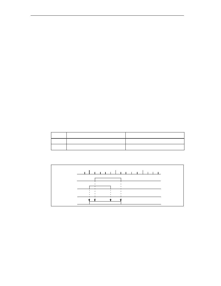
Example of a Track Result
During parameter assignment, you specify the following cams for track 3:
Cam
Cam start
Cam end
1
101
m
106
m
2
100
m
104
m
This results in the following track result:
Cam 1
Cam 2
Cam 3
track 3
105
m
100
m
110
m
s
Track result
Figure 2-1
Calculating the Track Result
Track Enable
To allow the track results of tracks 0 to 12 to be applied as track signals to the
digital outputs Q0 to Q12 of the FM 352, the tracks you are using must be enabled.

Basics of Cam Control
2-5
FM 352 Electronic Cam Controller
C79000-G7076-C352-04
External Enable of Track 3
You can set an external enable for track 3 in the machine data. The track signal 3
is then ANDed with digital input I3, before it can switch digital output Q3 of the
FM 352.
The digital output Q3 is switched when the following conditions are met:
•
The relevant track is enabled
•
At least one cam on this track is active (track result = 1).
•
The corresponding digital input I3 was set by an external event.
Setting the Track Signals
The track signals 0 to 12 (corresponding to digital outputs Q0 to Q12) can be set
via the cam controller or the CPU.
Basics of Cam Control
2-6
FM 352 Electronic Cam Controller
C79000-G7076-C352-04
2.2.2
Special Tracks
Definition
By setting the relevant parameters, you can set tracks 0 to 2 as special tracks, as
follows:
•
Track 0 or 1: Counter cam track
•
Track 2: Brake cam track
To allow the track to be activated, input I0 is evaluated.
Requirements
The following requirements must be met to allow the use of the special tracks:
•
Cams are assigned to the track
•
Cam processing is active
•
The relevant track is enabled
•
The track is selected as a special track
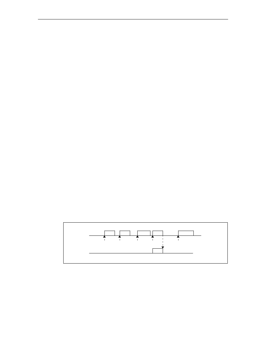
Counter Cam Track
A counter cam track counts the status changes of the track results on this track.
You must specify a value for the counter and start the counter function.
Each rising edge of the track result decrements the counter value of the relevant
track by 1.
As long as the counter value for the counter cam track is higher than 0, the track
flag bit remains 0.
Once the counter value reaches the value 0, the track flag bit is set and, if selected
in the parameter settings, the track signal is set (see Figure 2-4, page 2-11).
At the next falling edge of the track result (all cams on this track are off), the track
flag bit is cleared again and the counter is reset to the specified value.
Cam
Track 0
3
2
1
0
3
Track signal
Counter
reading
4
4
The maximum counter value set in the machine data is 1
Figure 2-2
Switching a Counter Cam Track
Basics of Cam Control
2-7
FM 352 Electronic Cam Controller
C79000-G7076-C352-04
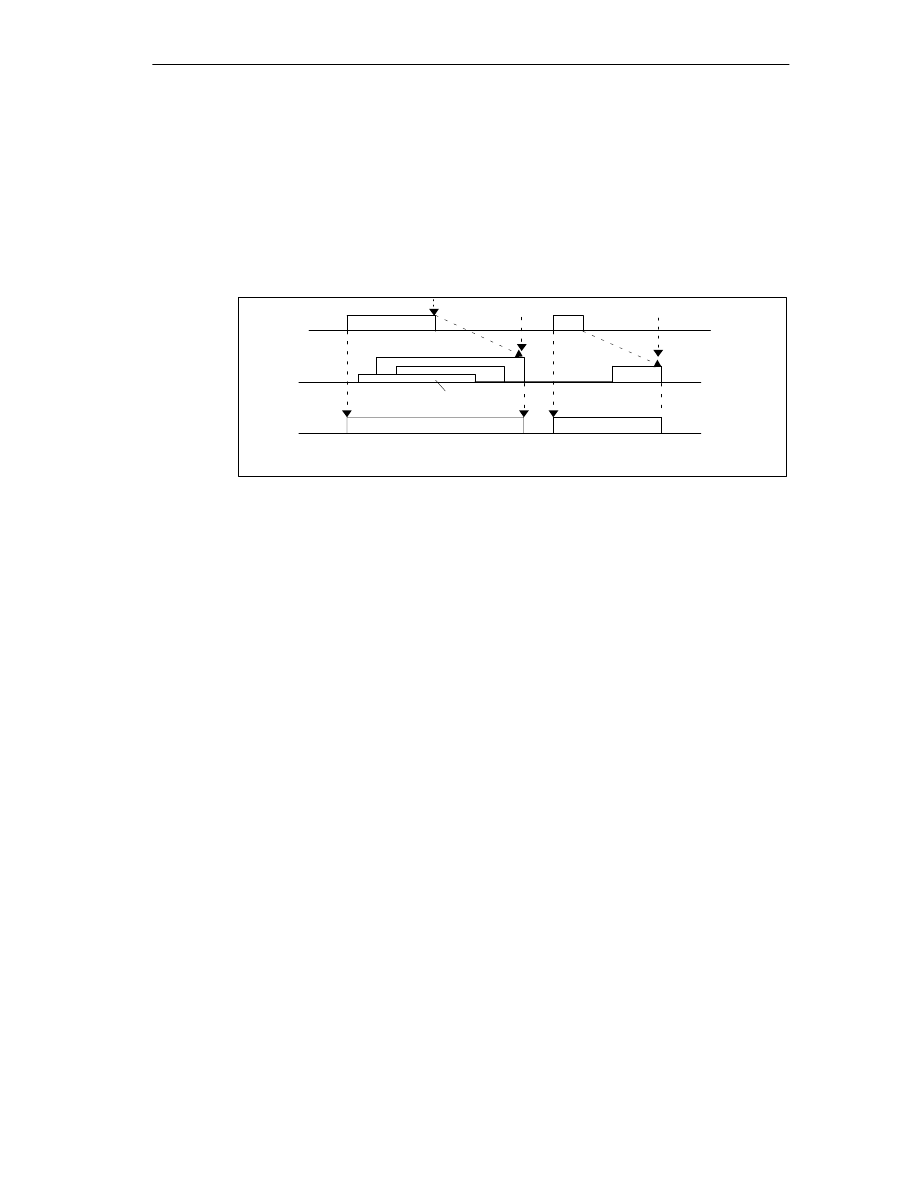
Brake Cam Track
To use track 2 as a brake cam track, digital input I0 must be connected.
A rising signal edge at I0 sets the track flag bit.
The track flag bit is reset again when:
•
There is no longer a “1” signal at I0 and afterwards
•
the falling edge of the track result of track 2 is detected.
I0
Cam
3
2
4
1
1 to 4 indicate 4 cams which influence the brake cam track
Brake enable
Braking point
Track flag bit
Track 2
Figure 2-3
Response of a Brake Cam Track
In the example (Figure 2-3), the track flag bit is deactivated by the falling edges of
cams 3 and 4.

Basics of Cam Control
2-8
FM 352 Electronic Cam Controller
C79000-G7076-C352-04
2.3
Hysteresis
Definition
Mechanical disturbances on the axis can cause changes in the actual position
value. If the actual position value fluctuates around the edge of a cam or within an
active cam with only one activation direction, this cam would be continuously
activated and deactivated. Hysteresis prevents this switching.
A hysteresis is dependent on the actual value and applies to all cams. It becomes
active as soon as a change of direction is detected. Hysteresis also takes effect
even if no cam is set at the current axis position.
Rules for the Hysteresis Range
The following rules apply to the hysteresis range:
•
Hysteresis is always activated when there is a change in direction.
•
Within the hysteresis, the indication of the actual value remains constant.
•
The direction is not changed within the hysteresis.
•
Within the hysteresis, a distance cam is neither activated nor deactivated.
•
Within the hysteresis, a time cam is not activated; an active time cam is
deactivated when the set activation time elapses (even within the hysteresis
range).
•
After leaving the hysteresis range, the FM 352 determines the following:
– the actual position value,
– The current direction of motion of the axis
– the current states of all cams
•
The hysteresis range applies to all cams.
Basics of Cam Control
2-9
FM 352 Electronic Cam Controller
C79000-G7076-C352-04
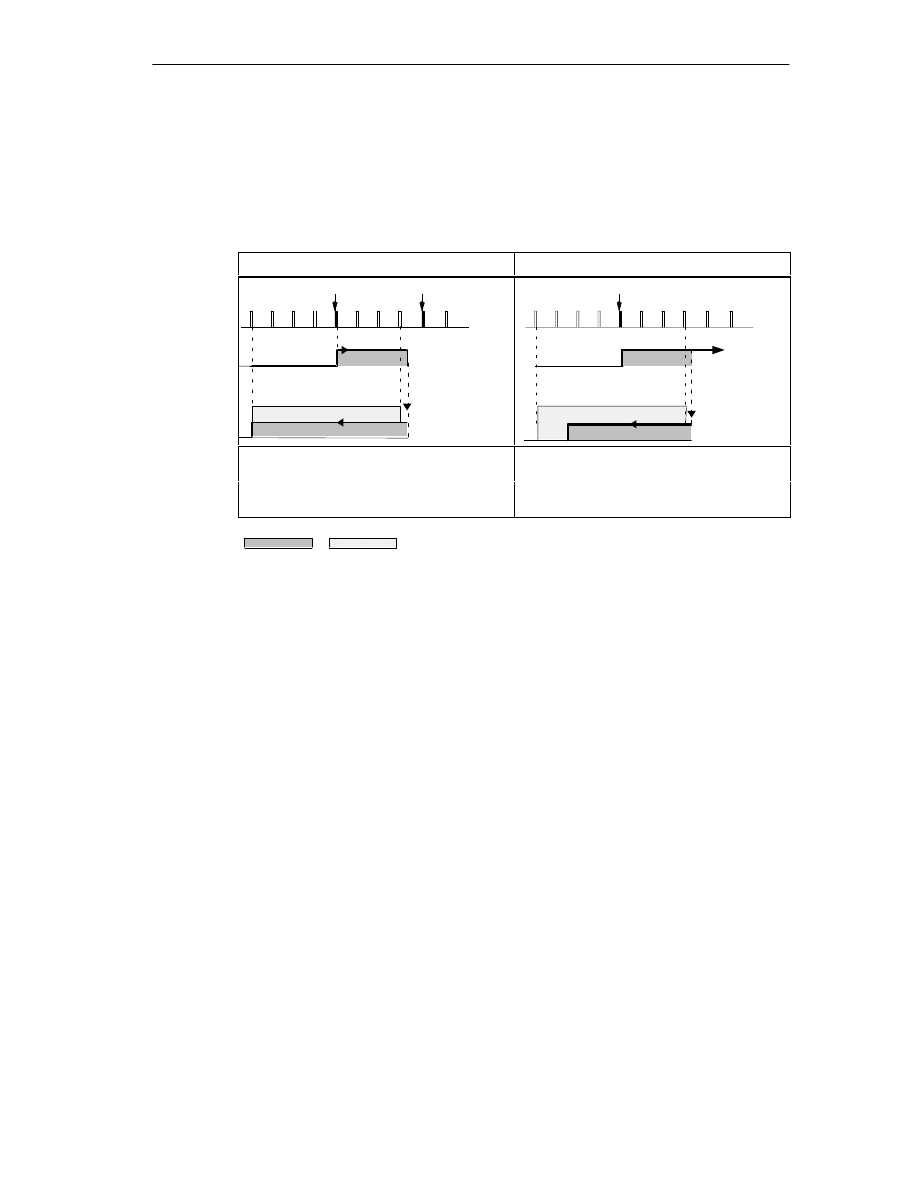
Effects of a Change of Direction on a Cam with Hysteresis
The following table illustrates the response of a cam when there is a change of
direction. A distinction must be made between the behavior of a distance cam and
a time cam. The activation direction of the cam is positive.
Table 2-2
Change of Direction on a Cam
Distance cam
Time cam
Change of
direction
CE
2 3
4 5
6 7
8 9
10
CS
Hysteresis
Distance cam
Distance cam
2
3
4
5
6 7
8 9 10
Change of
direction
CS
Time cam
Time cam
Hysteresis
The hysteresis becomes active after
change of direction is detected.
The cam always remains active for the
selected activation time.
g
The cam is deactivated once the
hysteresis range is exited.
Cam
Hysteresis

Basics of Cam Control
2-10
FM 352 Electronic Cam Controller
C79000-G7076-C352-04
2.4
Dynamic Adjustment
Task
The dynamic adjustment is used to compensate delays resulting from the
connected switching elements.
Lead Time
This delay can be specified as a lead time that you specify separately for each
cam. You can assign a lead time for each cam. The lead time applies to the cam
start and cam end.
Lead Distance
The lead distance of a cam is recalculated depending on the current feedrate and
the lead time. The entire cam is shifted in the direction of the actual value by this
distance. The range set is known as the “static range” and the range calculated
based on the lead time is known as the “dynamic range”.
Lead distance
lead time · current feedrate of the axis
Calculation of the lead distance of all cams is made within 1/4 of the longest set
lead time on the FM 352.
If you set a very large lead time for a cam, you reduce the dynamics of the cam
processing.
Basics of Cam Control
2-11
FM 352 Electronic Cam Controller
C79000-G7076-C352-04
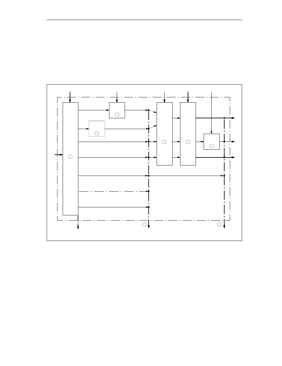
2.5
Interfaces of the Cam Controller
Overview
The schematic below shows the most important interfaces to illustrate the
relationship between data, inputs and outputs.
Cam Data
Encoder signals
Track 2
Cam flag bits of cam 0 to 127
1
Machine data
Channel DB
Q0 to Q2
Actual value, feedrate, direction
FM 352
2
Track
0 to 1
3
4
5
6
7
8
I0
Track flag bits, cam flag bits
and data
Track signals
Track 3
Tracks 4...12
Tracks 13...31
I3
Track 3
Q3
Q4 to Q12
Track result
Figure 2-4
Interfaces of the FM 352

Basics of Cam Control
2-12
FM 352 Electronic Cam Controller
C79000-G7076-C352-04
The schematic is explained in the table below.
No.
Description
Section
1
When the FM 352 processes the cams, the cam flag bits are calculated from the
switching conditions and the current actual value. The track results based on the
assignment of the cams to the tracks are also calculated.
2.1
(page 2-2)
2
If you have set track 0 or track 1 as a counter cam track, the track result of the cam
controller (point 1) is logically combined with the counter result to produce the track
flag bit. Otherwise, the track flag bit is the same as the track result.
2.2.2
(page 2-6)
3
If you have set track 2 as a brake cam track, the track result of the cam controller
(point 1) is logically combined with input I0 to produce the track flag bit. Otherwise,
the track flag bit is the same as the track result.
2.2.2
(page 2-7)
4
Using machine data, you can control whether the previously detected track flag bits
of tracks 0 to 12 of the cam controller are passed on or whether they are set directly
by the track enable (TRACK_EN).
8.7
(page 8-23),
9.15
(page 9-29)
5
You enable the track signals of tracks 0 to 12 with TRACK_EN and the count function
with CNTC0_EN / CNTC1_EN.
9.11
(page 9-25)
6
The track signal of track 3 can be ANDed with digital input I3 if you have enabled this
option in the machine data (EN_IN_I3).
8.7
(Page 8-23)
7
You can read out all the track and cam flag bits at this point (in other words before
they are logically combined with machine and channel data) using the job
ACTPOS_EN or CAMOUT_EN.
For tracks 3 to 31, the track flag bit is the same as the track result (point 1).
9.12
(page 9-26)
9.14
(page 9-28)
8
After being logically combined with the machine and channel data, the track signals
of tracks 0 to 12 are available in the return signals. The track signals of tracks 13 to
31 are identical to the track flag bits of point 7. The track signals of tracks 0 to 12 are
available at digital outputs Q0 to Q12.

3-1
FM 352 Electronic Cam Controller
C79000-G7076-C352-04
Installing and Removing the FM 352
Important Safety Rules
When integrating an S7-300 with an FM 352 in a plant or system, there are
important rules and regulations that are described in the installation manual
S7-300
Programmable Controller, Hardware and Installation.
Installation of the Rail
Horizontal installation of the rail is preferable.
If you install the rail vertically, remember the restrictions regarding the ambient
temperature (max. 40
°
C).
Selecting Slots
The FM 352 can be installed in any slot for signal modules on the rail.
Configuring the Mechanical Layout
The following rules apply to the arrangement of the modules in a rack:
1. A maximum of 8 FMs are permitted per tier.
2. The maximum number of modules is restricted by the length of the rail and the
width of the modules installed.
The FM 352 takes up a width of 80 mm.
3. The number of modules that can be installed (SM, FM, CP) is limited by their
current consumption from the S7-300 backplane bus.
The total current consumption from the S7-300 backplane bus of all modules
installed in a rack must not exceed 1.2 A with the CPU 313/314/314
IFM/315/315-2-DP/316-2 DP/318-2 and 0.8 A with the CPU 312 IFM.
The current consumption from the backplane bus of the FM 352 is 100 mA.
Tools Required for Installation and Removal
To install or remove the FM 352, you require a 4.5 mm screwdriver.
3

Installing and Removing the FM 352
3-2
FM 352 Electronic Cam Controller
C79000-G7076-C352-04
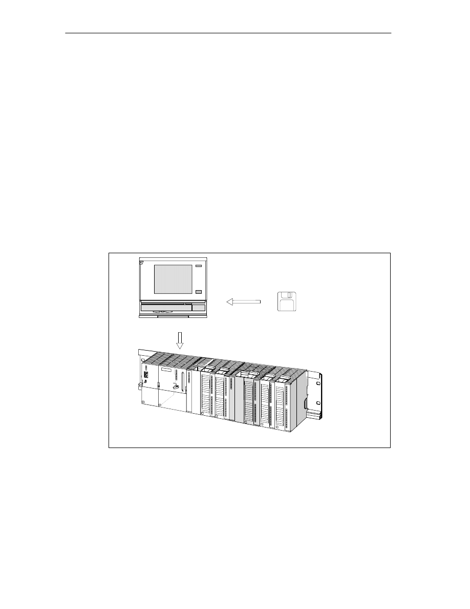
Installing the FM 352 Electronic Cam Controller
1. The FM 352 is supplied with a bus interconnector. Plug this onto the bus
connector of the module to the left of the FM 352. (The bus connector is on the
back of the module and you may need to loosen the module again first).
2. If further modules are installed to the right, first plug the bus interconnector of
the next module onto the right bus connector of the FM 352.
If the FM 352 is the last module in the tier, do not attach a bus interconnector!
3. Secure the FM 352 with screws (torque approximately 0.8 to 1.1 Nm).
4. After installation, you can assign a slot number to the FM 352. Slot labels are
supplied with the CPU.
The numbering scheme and numbering of slots and how to insert the slot labels
is described in the installation manual
S7-300 Programmable Controller,
Hardware and Installation.
5. Fit the shield contact element.
Order no.: 6ES7 390-5AA00-0AA0
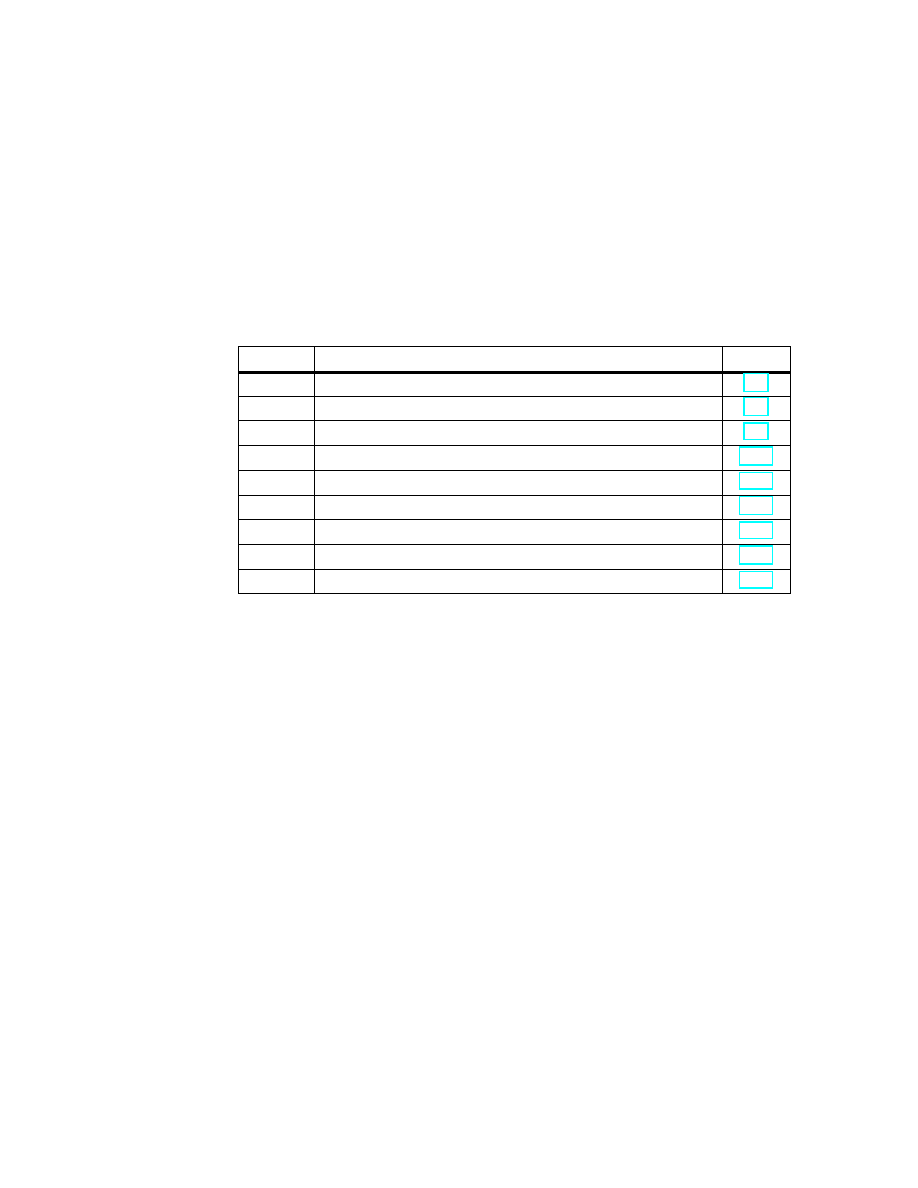
Removing the FM 352 Electronic Cam Controller
1. Switch off the power controller.
2. Turn off the 24 V supply for the FM 352.
3. Switch the CPU to STOP.
4. Open the front hinged panels.
Remove any labeling strips.
5. Unlock the front connector and remove it.
6. Remove the D sub connector to the encoder.
7. Undo the securing screw on the module.
8. Tilt the module upwards and remove it from the rail.
4-1
FM 352 Electronic Cam Controller
C79000-G7076-C352-04
Wiring the FM 352 Electronic Cam
Controller
Chapter Overview
Section
Contents
Page
4.1
Description of the Encoder Interface
4.2
Connecting the Encoder
4.3
Pinout of the Front Connector
4.4
Wiring of the Front Connector
Important Safety Rule
It is essential for the safety of the system to install the elements listed below and to
adapt them to your system.
•
EMERGENCY STOP switch with which you can turn off the entire system.
•
EMERGENCY STOP limit switches connected directly to the power units of all
drives.
•
Motor circuit-breaker.
4
Wiring the FM 352 Electronic Cam Controller
4-2
FM 352 Electronic Cam Controller
C79000-G7076-C352-04
4.1
Description of the Encoder Interface
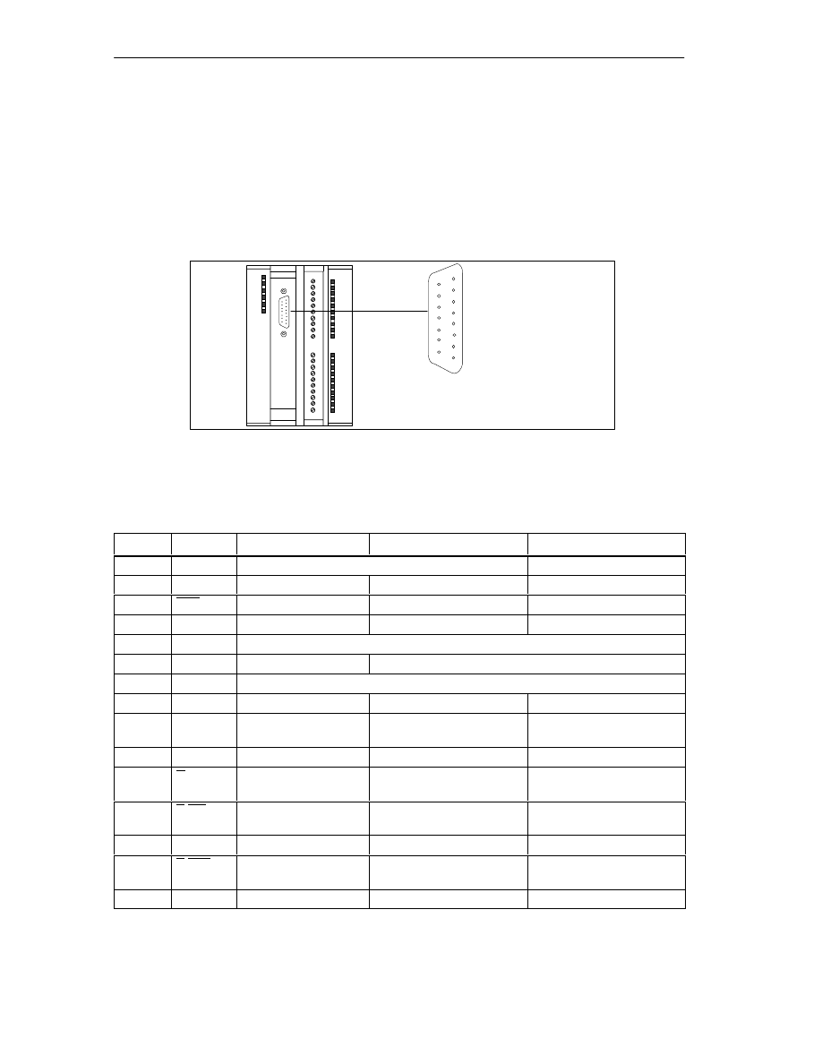
Location of the Sub D Connector
Figure 4-1 shows the location and labeling of the female connector on the module.
You can connect an initiator, incremental or absolute encoder (SSI) to the sub D
connector.
FM 352
1
15 8
9
ENCODER X2
Figure 4-1
Location of the Sub D Connector X2
Pinout of the Encoder Interface
Pin
Name
Initiator
Incremental Encoders
Absolute Encoders
1
A*
Encoder signal A (24 V)
---
2
CLS
---
---
SSI shift clock
3
CLS
---
---
SSI shift clock inverse
4
B*
---
Encoder signal B (24 V)
---
5
24 V DC
24 V encoder supply
6
5.2 V DC
---
Encoder supply 5.2 V
7
M
Ground
8
N*
---
Zero mark signal (24 V)
---
9
RE
---
Sourcing/sinking
(see Section B.3)
---
10
N
---
Zero mark signal (5 V)
---
11
N
---
Zero mark signal inverse
(5 V)
---
12
B/CLI
1
---
Encoder signal B inverse
(5 V)
SSI shift clock inverse
13
B/CLI
1
---
Encoder signal B (5 V)
SSI shift clock
14
A/DAT
---
Encoder signal A inverse
(5 V)
SSI data inverse
15
A / DAT
---
Encoder signal A (5 V)
SSI data
1
In listen-in mode

Wiring the FM 352 Electronic Cam Controller
4-3
FM 352 Electronic Cam Controller
C79000-G7076-C352-04
4.2
Connecting the Encoder
Shield Contact Element
Using the shield contact element, you can connect all shielded cables with ground
simply and easily making use of the direct connection between the shield contact
element and the rail.
For more detailed information, refer to the manual
S7-300 Programmable
Controller, Hardware and Installation.
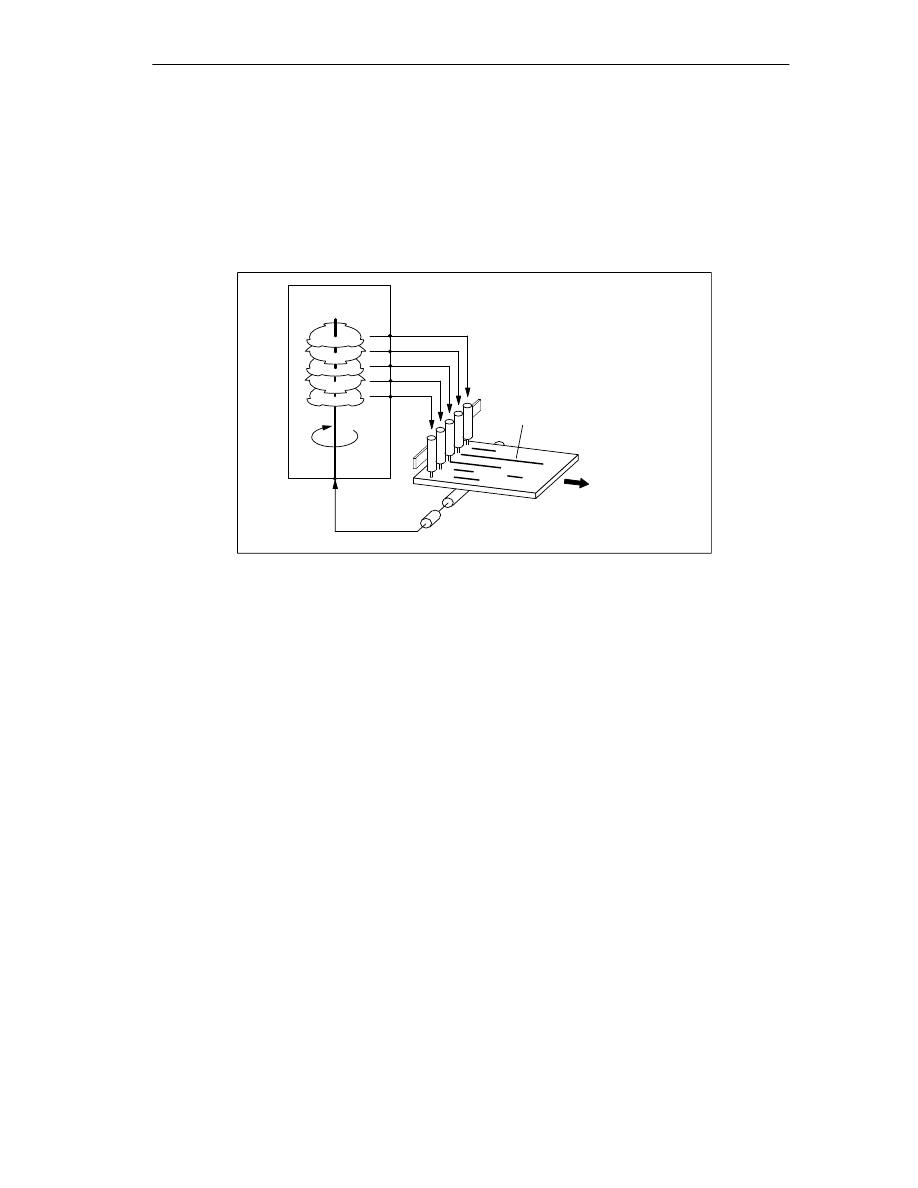
Procedure
Follow the steps outlined below to connect the encoder:
1. Connect the cable to the encoder.
With absolute encoders, it may be necessary to prepare the cable and fit a
connector to the encoder cable end according to the manufacturer’s
instructions.
2. Open the front panel and plug the sub D connector into the FM 352.
3. Secure the connector with the knurled screws. Close the front panel.
4. Remove the insulation from the cable and clamp the cable shield into the shield
contact element. Use shield clamps.

Wiring the FM 352 Electronic Cam Controller
4-4
FM 352 Electronic Cam Controller
C79000-G7076-C352-04
4.3
Pinout of the Front Connector
Front Connector
You connect the power supply and the switching elements via the front connector.
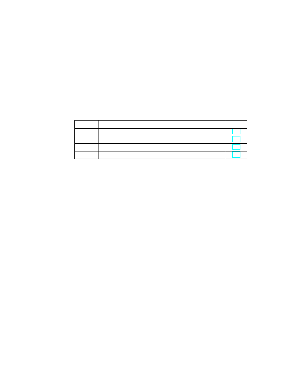
Pinout of the Front Connector
Terminal
Name
Meaning
1
L+
24 V DC encoder power supply and digital outputs
2
M
Encoder power supply and digital outputs ground
3
I0
Brake enable
4
I1
Length measurement/ edge detection/ setting actual value on-the-fly
5
I2
Reference point switch
6
I3
Enable track signal 3
7
Q0
Digital output 0
8
Q1
Digital output 1
9
Q2
Digital output 2
10
Q3
Digital output 3
11
Q4
Digital output 4
12
Q5
Digital output 5
13
Q6
Digital output 6
14
Q7
Digital output 7
15
Q8
Digital output 8
16
Q9
Digital output 9
17
Q10
Digital output 10
18
Q11
Digital output 11
19
Q12
Digital output 12
20
---
---

Wiring the FM 352 Electronic Cam Controller
4-5
FM 352 Electronic Cam Controller
C79000-G7076-C352-04
Auxiliary power for encoder and digital outputs (L+, M)
The 24 V DC auxiliary voltage of the encoders and digital outputs is monitored
•
for wirebreak of the 24 V feed line
•
for power failure
The 24 V DC auxiliary supply is converted internally to 5 V DC. This means that 24
V DC and 5 V DC are available on the encoder interface (sub D female connector
X2) for the different types of encoders.
The general technical specifications and requirements of the DC power supplies
are described in the installation manual
S7-300 Programmable Controller,
Hardware and Installation, CPU Data.
4 digital inputs (I0 to I3)
You can connect bounce-free switches (24 V current sourcing) or non-contact
sensors (2 or 3-wire proximity switches) to the 4 digital inputs.
The digital inputs are not monitored for short-circuits or wire break and are
connected to module chassis.
13 digital outputs (Q0 to Q12)
The state (on/off) of tracks 0 to 12 is output via 13 digital outputs. The digital
outputs are connected to module chassis.
The following loads directions are possible:
•
Operating voltage 24 V
•
Current load 0.5 A/short-circuit proof
A separate LED indicates the state of each output.

Wiring the FM 352 Electronic Cam Controller
4-6
FM 352 Electronic Cam Controller
C79000-G7076-C352-04
4.4
Wiring the Front Connector
Connecting Cords
•
The cords for digital inputs and digital outputs must be shielded if they exceed
certain lengths, as follows:
– digital inputs: cord length of more than 32 m
– digital ouputs: cord length of more than 100 m
•
The encoder cables must be shielded.
•
The shields of the encoder cables must make contact with the shield/protective
earth bar and the peripheral connector.
•
The wires A/DAT, A/DAT, B/CLI, B/CLI, CLS, CLS and N, N of the incremental
encoder must be twisted in pairs.
•
For the connecting cords, use flexible cord, cross-sectional area 0.25 to
1.5 mm
2
•
Ferrules are not necessary. If, however, you prefer to use them, you can use
ferrules without an insulation collar (DIN 46228, form A, short version) and two
cords each with 0.25 to 0.75 mm
2
in a ferrule.
Note
If you connect momentary-contact switches or proximity switches, you must use
shielded cords to achieve the optimum noise immunity.
Note on Wiring 24 V DC
!
Caution
The module can be damaged.
If you connect the encoder supply with the incorrect polarity, the module will be
damaged and must be replaced!
Make sure that the polarity of the encoder supply is correct (1L+, 1M).
Required Tools
3.5 mm screwdriver or motorized screwdriver

Wiring the FM 352 Electronic Cam Controller
4-7
FM 352 Electronic Cam Controller
C79000-G7076-C352-04
Procedure
!
Warning
Injury to persons or damage to equipment if the power supply is not turned off.
If you wire the front connector of the FM 352 while it is live, you risk injury from
electric shock.
Wire the FM 352 only when it is not live!
If no emergency stop switch is installed, damage can result from the connected
units.
Install an emergency stop switch with which you can turn off the connected drives
when you are controlling the FM 352 using the
Parameter Assignment User
Interface.
To wire up the front connector, follow the steps outlined below:
1. Remove 6 mm of insulation from the wire and, if required, crimp a ferrule onto
the wire.
2. Open the front panel and position the front connector for wiring.
3. Fit the strain relief to the connector.
4. If you want to lead the wires out at the bottom, start at the bottom, otherwise at
the top. Screw down unused terminals as well.
Use a torque of 0.6 ... 0.8 Nm.
5. Secure the cable with the strain relief.
6. Put the front connector into the operating position (pressing the securing
element).
7. You can complete the supplied label and insert it in the front panel.
Wiring the FM 352 Electronic Cam Controller
4-8
FM 352 Electronic Cam Controller
C79000-G7076-C352-04
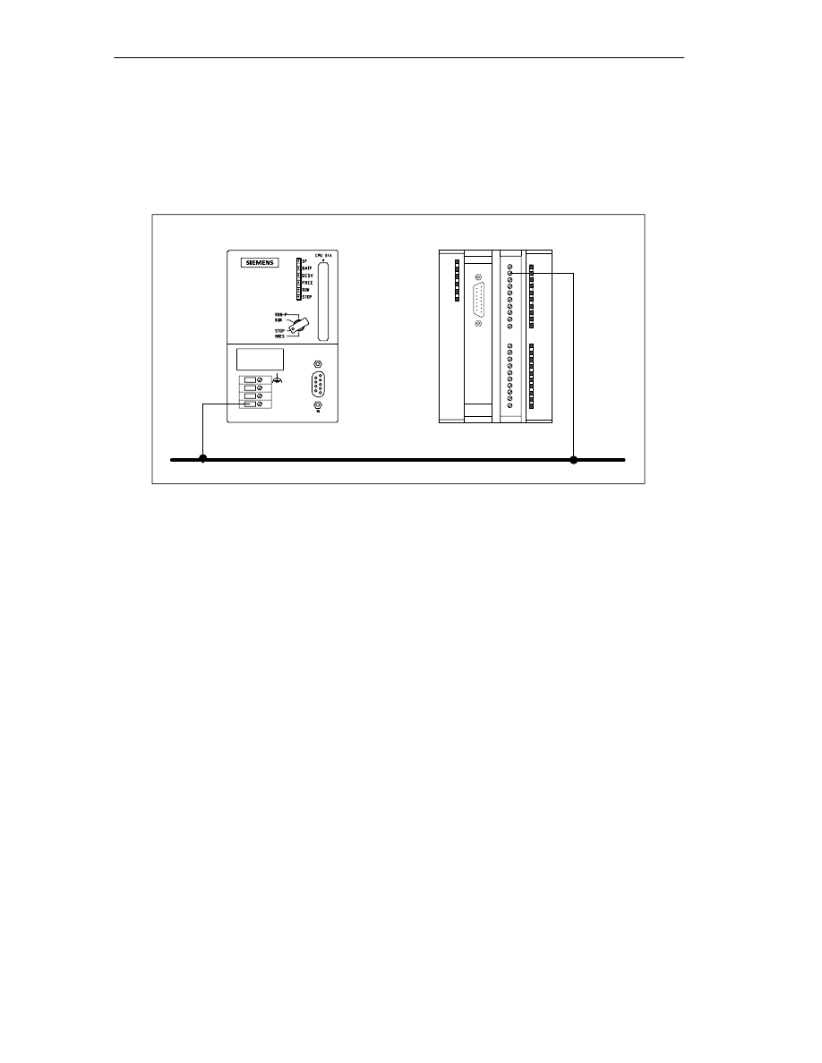
Ground Connection
The ground of the encoder supply is electrically connected to the ground of the
CPU; in other words, connect terminal 2 (1M) with the ground of the CPU or the
IM 153 with a low-resistance connection.
M
L+
M
Ground
CPU 314
FM 352
Terminal 2 (M)

5-1
FM 352 Electronic Cam Controller
C79000-G7076-C352-04
Installing the Software
Introduction
You make the required settings for the FM 352 using the
Parameter Assignment
User Interface. This user interface is intended for both the FM 352 and the
FM 452. You will find a description of the
Parameter Assignment User Interface in
the online help.
Requirements
Before you start to assign parameters for the FM 352 electronic cam controller,
you should check that the following requirements are met:
•
STEP 7, Version V4.02 or higher is correctly installed on your programming
device/PC.
Installation
The entire software is on the supplied CD. It is installed as follows:
1. Insert the CD in the drive on your programming device/PC.
2. Start the software installation dialog in Windows 95/Windows NT by clicking the
”Add/Remove Programs” icon in the ”Control Panel”.
3. In this dialog, select the CD drive and the folder FMx52\Disk1, then select the
file Setup.exe and start the installation.
4. Follow the instructions displayed by the installation program.
Result: The software is installed in the following folders:
– SIEMENS\STEP7\S7LIBS\FMx52LIB : FCs and UDTs
– SIEMENS\STEP7\S7FCAM : parameter assignment user interface, readme,
online help
– SIEMENS\STEP7\EXAMPLES\zEn19_01 : Example
– SIEMENS\STEP7\MANUAL: manual
Note
If you installed STEP 7 in a folder other than SIEMENS\STEP7, this folder is
entered.
Configuration and Parameter Assignment
These topics are described in Chapter 7.
5

Installing the Software
5-2
FM 352 Electronic Cam Controller
C79000-G7076-C352-04
6-1
FM 352 Electronic Cam Controller
C79000-G7076-C352-04
Programming the FM 352
Chapter Overview
Section
Contents
Page
6.1
Basics of Programming an FM 352
6.2
FC CAM_INIT (FC 0)
6.3
FC CAM_CTRL (FC 1)
6.4
FC CAM_DIAG (FC 2)
6.5
Data Blocks
6.6
Interrupts
6.7
Technical Specifications
6.8
Fast Access to Module Data
6.9
Parameter Transfer Routes
6

Programming the FM 352
6-2
FM 352 Electronic Cam Controller
C79000-G7076-C352-04
6.1
Basics of Programming an FM 352
Task
You can assign parameters, control and start up the FM 352 module in a user
program. To exchange data between the user program and module, you use the
functions (FCs) and data blocks (DBs) described below.
Preparations
•
Open the block library FMx52LIB in the SIMATIC Manager and copy the
required functions (FCs) and block templates (UDTs) to the block folder of your
project. If the block numbers are already being used, assign new numbers. The
block names are entered unchanged in the symbol table of your S7 program.
– CAM_INIT (FC 0):
This is required to initialize the channel DB following a module startup.
– CAM_CTRL (FC 1):
This is required for data exchange with the module.
– CAM_DIAG (FC 2):
This is required when you process detailed diagnostic information in the
program or want to make this information available to an operator control
and monitoring system.
– CAM_MSRM (FC 3):
can only be used with the FM 452
– CAM_CHANTYPE (UDT1):
This is required to generate a channel DB; this is used by FC CAM_INIT,
CAM_CTRL and CAM_MSRM.
– CAM_DIAGTYPE (UDT2):
This is required to generate a diagnostic DB; this is used by FC CAM_DIAG.
– CAM_P016TYPE (UDT3):
This is required to generate a parameter DB with machine data and data for
16 cams; this is used by FC CAM_CTRL to write or read machine or cam
data.
– CAM_P032TYPE (UDT4):
Same as CAM_P016TYPE, however for 32 cams.
– CAM_P064TYPE (UDT5):
Same as CAM_P016TYPE, however for 64 cams.
– CAM_P128TYPE (UDT6):
Same as CAM_P016TYPE, however for 128 cams.

Programming the FM 352
6-3
FM 352 Electronic Cam Controller
C79000-G7076-C352-04
•
Create data blocks using the UDTs in the block folder of your S7 program. If
you use several modules, you require a separate set of data blocks for each
module.
•
Enter the module address in the channel DB and, if used in the diagnostic DB,
also at the address MOD_ADDR. You can also have the address entered
automatically by selecting the module in HW Config and then selecting a data
block in the “Properties” dialog with the “Mod Addr” button.
•
If your programming device/PC is connected to a CPU, you can now download
the FCs and DBs to the CPU.

Programming the FM 352
6-4
FM 352 Electronic Cam Controller
C79000-G7076-C352-04
6.2
FC CAM_INIT (FC 0)
Tasks
FC CAM_INIT initializes the following data in the channel DB:
•
The control signals
•
The return signals
•
The trigger, done, error bits of the jobs
•
The function switches and their done and error bits
•
The job management and the internal buffers for FC CAM_CTRL and
FC CAM_MSRM
Call
The function must be run through following a startup (power supply on) on the
module or CPU. You should therefore install it, for example in the warm restart OB
(OB100) and the remove/insert OB (OB83) or call it in the initialization phase of
your user program. This ensures that your user program does not access old data
following a CPU restart or a module startup.
Call Parameters
Name
Data Type
I/O
Meaning
DB_NO
INT
I
Number of the Channel DB
Return Values
This function does not return a value.

Programming the FM 352
6-5
FM 352 Electronic Cam Controller
C79000-G7076-C352-04
6.3
FC CAM_CTRL (FC 1)
Tasks
With FC CAM_CTRL, you can read the operating data from the module, initialize
the module, and control it during operation. For these tasks, you use the control
signals, return signals and write and read jobs.
Each time it is called, the function performs the following activities:
•
Read return signals:
FC CAM_CTRL reads all return signals from the module and enters them in the
channel DB. Since the control signals and jobs are only executed following this,
the return signals reflect the status of the module before the block was called.
•
Write control signals:
The control signals entered in the channel DB are transferred to the module.
The enabling of the cam processing is, however, delayed as long as the trigger
for a “set reference point” or “write cam data” job is set. The activation (or
reactivation) of cam processing is delayed for this time.
•
Execute job:
The next job is executed based on the trigger bits for jobs entered in the
channel DB.
Call
This function must be called cyclically.
Before you call the function, enter all the data in the channel DB that are required
to execute the intended functions.
Data Used
•
Channel DB:
The module address must be entered in the channel DB.
•
Parameter DB:
If you want to write or read machine or cam data using jobs, you require a
parameter DB whose number must be entered in the channel DB. The size of
the parameter DB must be adequate for the number of cams.

Programming the FM 352
6-6
FM 352 Electronic Cam Controller
C79000-G7076-C352-04
Jobs
Data exchange with the module other than the control and return signals is handled
using jobs.
To start a job, you set the corresponding trigger bit in the channel DB and provide
the relevant data for write jobs. You then call FC CAM_CTRL to execute the job.
If you use the FM 352 centrally, a read job is executed immediately. If you use the
FM 352 decentrally, a read job may take several cycles.
Due to the required confirmations from the module, a write job requires at least
three calls (or OB cycles).
You can send several jobs at the same time, if necessary, along with control
signals. Apart from the job for writing the function switch, the jobs are executed in
the order of the trigger bits as specified in the channel DB. Once a job has been
completed, the trigger bit is reset. The next time the block is called, the next job is
located and executed.
For each job there is not only a trigger bit but also a done bit and an error bit. In
their names, instead of the ending _EN (for “enable“), they have the ending _D (for
“done“) or _ERR (for “error”). Done and error bits of the job should be set to 0 after
they have been evaluated or before the job is started.
If you set the JOBRESET bit, all the done and error bits are reset before the
pending jobs are processed. The JOBRESET bit is then set to 0 again.
Function Switches
The function switches activate and deactivate module states. A job for writing the
function switches is only executed when there is a change in a switch setting. It is
always executed between the jobs “set reference point” (REFPT_EN) and “set
actual value” (AVAL_EN). The setting of the function switch is latched after the job
has been executed.
Length measurements and edge detection must not be activated at the same time.
FC CAM_CTRL makes sure that when one of the function switches is activated,
the other is deactivated. If you do switch both function switches at the same time
(0 -> 1), the length measurement is activated.
Function switches and jobs can be used at the same time in one FC CAM_CTRL
call.
As with the jobs, there are done bits with the ending _D and error bits with the
ending _ERR for the function switches.
To be able to evaluate the done and error bits, you should set these bits to 0 when
you change a function switch.

Programming the FM 352
6-7
FM 352 Electronic Cam Controller
C79000-G7076-C352-04
Startup
When the module or CPU starts up, call FC CAM_INIT (see Section 6.2,
Page 6-4). Among other things, the function switches are reset.
FC CAM_CTRL acknowledges the module startup. During this time, RET_VAL and
JOBBUSY are set to 1.
Call Parameters
Name
Data Type
I/O
Meaning
DB_NO
INT
I
Number of the Channel DB
RET_VAL
INT
O
Return value
Return Values
The function provides the following return values:
RET_VAL
BR
Description
1
1
At least one job active
0
1
No job active, no error
-1
0
Error:
Data error (DAT_ERR) or
Communication error (JOB_ERR) occurred

Programming the FM 352
6-8
FM 352 Electronic Cam Controller
C79000-G7076-C352-04
Job Status
You can check the status of job execution using the return value RET_VAL and the
JOBBUSY activity bit in the channel DB. You can evaluate the status of a single
job based on the trigger, done, and error bits of the job.
•
Job active:
– RET_VAL = 1
– JOBBUSY = 1
– Trigger bit = 1
– Done bit = 0
– Error bit = 0
•
Job completed without error:
– RET_VAL = 0
– JOBBUSY = 0
– Trigger bit = 0
– Done bit = 1
– Error bit = 0
•
Job completed with error in this job:
– RET_VAL = -1
– JOBBUSY = 0
– Trigger bit = 0
– Done bit = 1
– Error bit = 1
•
Write job aborted:
– RET_VAL = -1
– JOBBUSY = 0
– Trigger bit = 0
– Done bit = 0
– Error bit = 1

Programming the FM 352
6-9
FM 352 Electronic Cam Controller
C79000-G7076-C352-04
Response to Errors
If bad data were written by a write job, the module returns the message
DATA_ERR = 1. If an error occurs in communication with the module during a write
or read job, the cause of the error is entered in the JOB_ERR parameter in the
channel DB.
•
Error in a write job:
If an error occurs in a job, the trigger bit is reset and the error bit (_ERR) and
the done bit (_D) are set. The trigger bit is reset and the error bit (_ERR) is set
for all write jobs still pending.
The pending read jobs continue to be processed. JOB_ERR is set again for
each job.
•
Error in a read job:
If an error occurs in a job, the trigger bit is reset and the error bit (_ERR) and
the done bit (_D) are set.
The read jobs still pending continue to be processed. JOB_ERR is set again for
each job.
For more detailed information on the errors, refer to the parameters JOB_ERR and
DATA_ERR (see Chapter 11, Diagnostics and Appendix C.3, Page C-12)

Programming the FM 352
6-10
FM 352 Electronic Cam Controller
C79000-G7076-C352-04
6.4
FC CAM_DIAG (FC 2)
Tasks
Using FC CAM_DIAG, you read out the diagnostic buffer of the module and can
make it available for display in an operator control and monitoring system or for
programmed evaluation.
Call
This function must be called cyclically. A further job in an interrupt OB is not
permitted. For complete execution of this function, at least two calls (cycles) are
required.
The function reads the diagnostic buffer when a new entry is indicated in the
diagnostic buffer by the return signal DIAG = 1. After reading the diagnostic buffer,
DIAG is set to 0 by the module.
Data Used
•
Diagnostic DB:
The module address must be entered in the diagnostic DB. The latest entry in
the diagnostic buffer is entered in the DIAG[1] structure and the oldest entry in
the DIAG[4] structure.
Jobs
You can read the diagnostic buffer whether or not there is a new entry by setting
the DIAGRD_EN trigger bit. After reading the diagnostic buffer, the trigger bit is set
to 0.
Startup
There is no startup processing associated with the function.
Call Parameters
Name
Data Type
I/O
Meaning
DB_NO
INT
I
Number of the diagnostic DB
RET_VAL
INT
O
Return value

Programming the FM 352
6-11
FM 352 Electronic Cam Controller
C79000-G7076-C352-04
Return Values
The function provides the following return values:
RET_VAL
BR
Description
1
1
Job active
0
1
No job active, no error
-1
0
Error:
Response to Errors
If an error occurs in a job, the cause of the error can be found in the diagnostic DB
in the JOB_ERR parameter (see Chapter 11, Diagnostics and Appendix C.3,
Page C-12).

Programming the FM 352
6-12
FM 352 Electronic Cam Controller
C79000-G7076-C352-04
6.5
Data Blocks
6.5.1
Templates for Data Blocks
The supplied library (FMx52LIB) contains a block template (UDT) for each data
block. Based on this UDT, you can create data blocks with any numbers and
names.
Optimizing the UDT
To save memory, you can delete unused data areas at the end of the UDT
CAM_CHANTYPE. You can then save the modified UDT under a different name.
You can then generate a channel DB based on this UDT that is optimized for your
application.
Functions that access deleted data areas can no longer be used.
The supplied UDT for the machine and cam data are matched already to the
possible numbers of cams. They can be optimized in steps of 16 cams.
6.5.2
Channel DB
Task
The channel DB is the data interface between the user program and the FM 352
electronic cam controller. All the data required for controlling and operating the
module is entered in this data block.
Structure
The channel DB is subdivided into various areas:
Channel DB
Control signals
Return signals
Trigger bits for read jobs
Function switches
Trigger bits for write jobs
Done bits
Address
*)
/version switch
Data for jobs
Job management for functions
*) You can enter the address in
the parameter assignment user interface.
Error bits

Programming the FM 352
6-13
FM 352 Electronic Cam Controller
C79000-G7076-C352-04
6.5.3
Diagnostic DB
Task
The diagnostic DB provides the data storage for FC CAM_DIAG and contains the
diagnostic buffer of the module created by this function.
Structure
Diagnostic DB
Internal data
Job status
Trigger bit
Diagnostic buffer
Module address
6.5.4
Parameter DB
Task
The machine and cam data are stored in the parameter DB. The parameters can
be modified by the user program or by an operator control and monitoring system.
The modified data can be imported into the parameter assignment user interface
and displayed there. You can export the data displayed in the parameter
assignment user interface to a parameter DB.
There can be several sets of parameter assignment data for a module (for
example, for various recipes) that you can activate program-controlled.
Structure
Parameter DB
Machine data
Cam data of cams 0 to 31
Cam data of cams 0 to 63
Cam data of cams 0 to 127
Cam data of cams 0 to 15
CAM_P016TYPE (UDT3)
CAM_P032TYPE (UDT4)
Machine data
CAM_P064TYPE (UDT5)
CAM_P0128TYPE (UDT6)
Machine data
Machine data

Programming the FM 352
6-14
FM 352 Electronic Cam Controller
C79000-G7076-C352-04
6.6
Interrupts
Interrupt Handling
The FM 352 can trigger hardware interrupts and diagnostic interrupts. You service
these interrupts in an interrupt OB. If an interrupt is triggered and the
corresponding OB is not loaded, the CPU changes to STOP (refer to the manual
Programming with STEP 7).
You can enable interrupt servicing at the following levels:
1. Enabling general interrupts for the entire module:
– Select the module in HW Config
– Using the menu command Edit > Object Properties > Basic Parameters,
enable diagnostic and/or hardware interrupts.
– Select the OB number for the hardware interrupt using Edit > Object
Properties > Addresses.
– Save and compile the hardware configuration.
– Download the hardware configuration to the CPU.
2. Enabling events for hardware interrupts in the machine data.
3. Setting parameters for hardware interrupts in the cam data for cams 0 to 7.
Evaluation of a Hardware Interrupt
If a hardware interrupt is triggered by the FM 352, the following information is
available in the variable OB40_POINT_ADDR (or in the corresponding variable of
a different hardware interrupt OB):
Table 6-1
Content of the Double Word OB40_POINT_ADDR
Byte
Bit 7
Bit 6
Bit 5
Bit 4
Bit 3
Bit 2
Bit 1
Bit 0
0
0
0
0
0
0
0
0
0
1
0
0
0
0
0
Cam
0
0
2
Cam 7
on
Cam 7
off
Cam 6
on
Cam 6
off
Cam 5
on
Cam 5
off
Cam 4
on
Cam 4
off
3
Cam 3
on
Cam 3
off
Cam 2
on
Cam 2
off
Cam 1
on
Cam 1
off
Cam 0
on
Cam 0
off
You can see the cause of the interrupt in Byte 1:
Cam: Evaluate byte 2 and byte 3 according to the table.

Programming the FM 352
6-15
FM 352 Electronic Cam Controller
C79000-G7076-C352-04
Lost Hardware Interrupts
If the processing of a hardware interrupt is not yet completed in the hardware
interrupt OB, the module registers all subsequent hardware interrupt events. If an
event occurs again before the hardware interrupt could be triggered, the module
triggers the “hardware interrupt lost” diagnostic interrupt.
Evaluating a Diagnostic Interrupt
Following a diagnostic interrupt, the diagnostic information is available in the
variables of OB82 and can be used for fast analysis. Call the CAM_DIAG function
to find out the exact cause of the problem as entered in the diagnostic buffer.
The local data of the diagnostic interrupt OB that are supported are listed below.
Variable
Data
Type
Description
OB82_MDL_DEFECT
BOOL
Module fault
OB82_INT_FAULT
BOOL
Internal error
OB82_EXT_FAULT
BOOL
External error
OB82_PNT_INFO
BOOL
Channel error
OB82_EXT_VOLTAGE
BOOL
External auxiliary voltage missing
OB82_FLD_CONNCTR
BOOL
No front connector
OB82_WTCH_DOG_F
BOOL
Watchdog monitoring has responded
OB82_INT_PS_FLT
BOOL
Internal module power supply failed
OB82_HW_INTR_FLT
BOOL
Hardware interrupt lost

Programming the FM 352
6-16
FM 352 Electronic Cam Controller
C79000-G7076-C352-04
6.7
Technical Specifications
The following table provides an overview of the technical specifications of the
functions.
Table 6-2
Technical Specifications for the FM 352 Functions
No.
Block Name
Versi
on
Space
Occupied
in Load
Memory
(bytes)
Space
Occupied
in Main
Memory
(bytes)
Space
Occupied in
Local Data
Area
(bytes)
MC7
Code/Data
(bytes)
Called
System Functions
FC0
FC CAM_INIT
1.0
192
138
2
102
ÁÁÁ
ÁÁÁ
ÁÁÁ
FC 1
ÁÁÁÁÁÁ
ÁÁÁÁÁÁ
ÁÁÁÁÁÁ
FC CAM_CTRL
ÁÁÁ
ÁÁÁ
ÁÁÁ
1.0
ÁÁÁÁ
ÁÁÁÁ
ÁÁÁÁ
5232
ÁÁÁÁ
ÁÁÁÁ
ÁÁÁÁ
4754
ÁÁÁÁÁ
ÁÁÁÁÁ
ÁÁÁÁÁ
32
ÁÁÁÁ
ÁÁÁÁ
ÁÁÁÁ
4718
ÁÁÁÁÁÁÁ
ÁÁÁÁÁÁÁ
ÁÁÁÁÁÁÁ
SFC 58: WR_REC,
SFC 59: RD_REC
ÁÁÁ
ÁÁÁ
FC2
ÁÁÁÁÁÁ
ÁÁÁÁÁÁ
FC CAM_DIAG
ÁÁÁ
ÁÁÁ
1.0
ÁÁÁÁ
ÁÁÁÁ
1758
ÁÁÁÁ
ÁÁÁÁ
1614
ÁÁÁÁÁ
ÁÁÁÁÁ
42
ÁÁÁÁ
ÁÁÁÁ
1578
ÁÁÁÁÁÁÁ
ÁÁÁÁÁÁÁ
SFC 59: RD_REC
Channel DB
-
986
804
-
372
Parameter DB 16
Parameter DB 32
Parameter DB 64
Parameter DB 128
-
-
-
-
616
808
1192
1960
336
528
912
1680
-
-
-
-
300
492
876
1644
Diagnostic DB
-
460
338
-
302
Module Cycle
The module updates the return data (except in the pulses measuring system)
every 4 ms.
In the pulses measuring system, the data for the actual position value and the
track signals are available after 1 ms.

Programming the FM 352
6-17
FM 352 Electronic Cam Controller
C79000-G7076-C352-04
Execution Times
The following table provides you with an overview of the execution times of the
functions for the FM 352. The run time from the first function call to the done
message (trigger bit reset) is shown. The cycle is extended by calling a function by
between 8 and 12 ms for write jobs and by the length of the execution time for read
jobs.
Table 6-3
Execution Times of the Functions for the FM 352
Block
Block Name/Job
CPU 315-2 (6ES7 315-2AF01-0AB0)
Block
Block Name/Job
Run time in ms
FC0
FC CAM_INIT
0.14
ÁÁÁÁ
ÁÁÁÁ
ÁÁÁÁ
ÁÁÁÁ
ÁÁÁÁ
ÁÁÁÁ
ÁÁÁÁ
ÁÁÁÁ
ÁÁÁÁ
ÁÁÁÁ
ÁÁÁÁ
ÁÁÁÁ
ÁÁÁÁ
ÁÁÁÁ
ÁÁÁÁ
ÁÁÁÁ
ÁÁÁÁ
ÁÁÁÁ
ÁÁÁÁ
ÁÁÁÁ
ÁÁÁÁ
FC 1
ÁÁÁÁÁÁÁÁÁÁÁÁÁÁÁ
ÁÁÁÁÁÁÁÁÁÁÁÁÁÁÁ
ÁÁÁÁÁÁÁÁÁÁÁÁÁÁÁ
ÁÁÁÁÁÁÁÁÁÁÁÁÁÁÁ
ÁÁÁÁÁÁÁÁÁÁÁÁÁÁÁ
ÁÁÁÁÁÁÁÁÁÁÁÁÁÁÁ
ÁÁÁÁÁÁÁÁÁÁÁÁÁÁÁ
ÁÁÁÁÁÁÁÁÁÁÁÁÁÁÁ
ÁÁÁÁÁÁÁÁÁÁÁÁÁÁÁ
ÁÁÁÁÁÁÁÁÁÁÁÁÁÁÁ
ÁÁÁÁÁÁÁÁÁÁÁÁÁÁÁ
ÁÁÁÁÁÁÁÁÁÁÁÁÁÁÁ
ÁÁÁÁÁÁÁÁÁÁÁÁÁÁÁ
ÁÁÁÁÁÁÁÁÁÁÁÁÁÁÁ
ÁÁÁÁÁÁÁÁÁÁÁÁÁÁÁ
ÁÁÁÁÁÁÁÁÁÁÁÁÁÁÁ
ÁÁÁÁÁÁÁÁÁÁÁÁÁÁÁ
ÁÁÁÁÁÁÁÁÁÁÁÁÁÁÁ
ÁÁÁÁÁÁÁÁÁÁÁÁÁÁÁ
ÁÁÁÁÁÁÁÁÁÁÁÁÁÁÁ
ÁÁÁÁÁÁÁÁÁÁÁÁÁÁÁ
FC CAM_CTRL
Control/return
MDWR_EN
MDWR_EN and MD_EN
CAM1WR_EN (0 cam enabled)
CAM1WR_EN (16 cams enabled)
REFPT_EN
SIM_ON
AVAL_EN
FVAL_EN
ZOFF_EN
CH01CAM_EN
CH16CAM_EN (1 cam with check)
CH16CAM_EN (1 cam without check)
CH16CAM_EN (16 cams with check)
CH16CAM_EN (16 cams without check)
MDRD_EN
CAM1RD_EN
MSRRD_EN
CNTTRC_EN
ACTPOS_EN
ENCVAL_EN
CAMOUT_EN (FM_TYPE = 0, 16 bytes)
CAMOUT_EN (FM_TYPE = 1, 24 bytes)
ÁÁÁÁÁÁÁÁÁÁÁÁ
ÁÁÁÁÁÁÁÁÁÁÁÁ
ÁÁÁÁÁÁÁÁÁÁÁÁ
ÁÁÁÁÁÁÁÁÁÁÁÁ
ÁÁÁÁÁÁÁÁÁÁÁÁ
ÁÁÁÁÁÁÁÁÁÁÁÁ
ÁÁÁÁÁÁÁÁÁÁÁÁ
ÁÁÁÁÁÁÁÁÁÁÁÁ
ÁÁÁÁÁÁÁÁÁÁÁÁ
ÁÁÁÁÁÁÁÁÁÁÁÁ
ÁÁÁÁÁÁÁÁÁÁÁÁ
ÁÁÁÁÁÁÁÁÁÁÁÁ
ÁÁÁÁÁÁÁÁÁÁÁÁ
ÁÁÁÁÁÁÁÁÁÁÁÁ
ÁÁÁÁÁÁÁÁÁÁÁÁ
ÁÁÁÁÁÁÁÁÁÁÁÁ
ÁÁÁÁÁÁÁÁÁÁÁÁ
ÁÁÁÁÁÁÁÁÁÁÁÁ
ÁÁÁÁÁÁÁÁÁÁÁÁ
ÁÁÁÁÁÁÁÁÁÁÁÁ
ÁÁÁÁÁÁÁÁÁÁÁÁ
0.55
123.8
132.1
26.3
92.9
13.4
12.3
15.1
13.8
14.2
15.7
18.0
17.6
104.5
94.1
13.4
18.1
8.8
8.2
8.8
8.8
8.9
9.5
FC2
FC CAM_DIAG
Idle run
Read diagnostic buffer
0.27
14.4
FC 3
FC CAM_MSRM
2.5

Programming the FM 352
6-18
FM 352 Electronic Cam Controller
C79000-G7076-C352-04
6.8
Fast Access to Module Data
Application
In special applications or in an interrupt level, particularly fast access to return and
control signals is necessary. You can obtain this data directly via the input and
output areas of the module.
To coordinate startup following each module startup (for example after inserting the
module, CPU STOP
→
RUN), FC CAM_CTRL must be called continuously until
the end of the startup is indicated by RET_VAL = 0.
Note
If you access data on the FM 352 directly, you must only use the non-internal data
described here using the method described here. Otherwise, your user program
will encounter difficulties accessing the module.
Direct Access for Reading Return Signals
The byte addresses are specified relative to the output address of the module.
The names of the bits correspond to the names in the channel DB.
In STL, you access the data with the commands PIB (read 1 byte) and PID
(read 4 bytes).
Address
Bit number
7
6
5
4
3
2
1
0
Byte 0
PARA
internal
internal
DATA_ERR
internal
DIAG
internal
internal
Byte 1
0
0
0
CAM_ACT
0
0
0
0
Byte 2
internal
Byte 3
0
0
FVAL_
DONE
HYS
GO_P
GO_M
MSR_D
ONE
SYNC
Byte 4
Byte 5
ACT_POS
Byte 6
Byte 7
Byte 8
Byte 9
TRACK_OUT
Byte 10
Byte 11
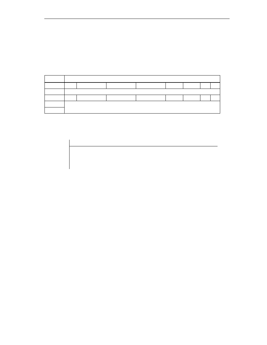
Programming the FM 352
6-19
FM 352 Electronic Cam Controller
C79000-G7076-C352-04
Direct Access for Writing Control Signals
The byte addresses are specified relative to the input address of the module. The
names of the bits correspond to the names in the channel DB.
In STL, you access the data with the commands PQB (write 1 byte) and PQW
(write 2 bytes).
Address
Bit number
7
6
5
4
3
2
1
0
Byte 0
internal
Byte 1
0
CNTC1_EN
CNTC0_EN
CAM_EN
DIR_P
DIR_M
0
0
Byte 2
TRACK_EN
Byte 3
Example: Actual position value (ACT_POS)
STL
Explanation
Example
L PID 516
The base address of the module is 512
Read the current actual position value
(ACT_POS) with direct access:
Base address of the module + 4
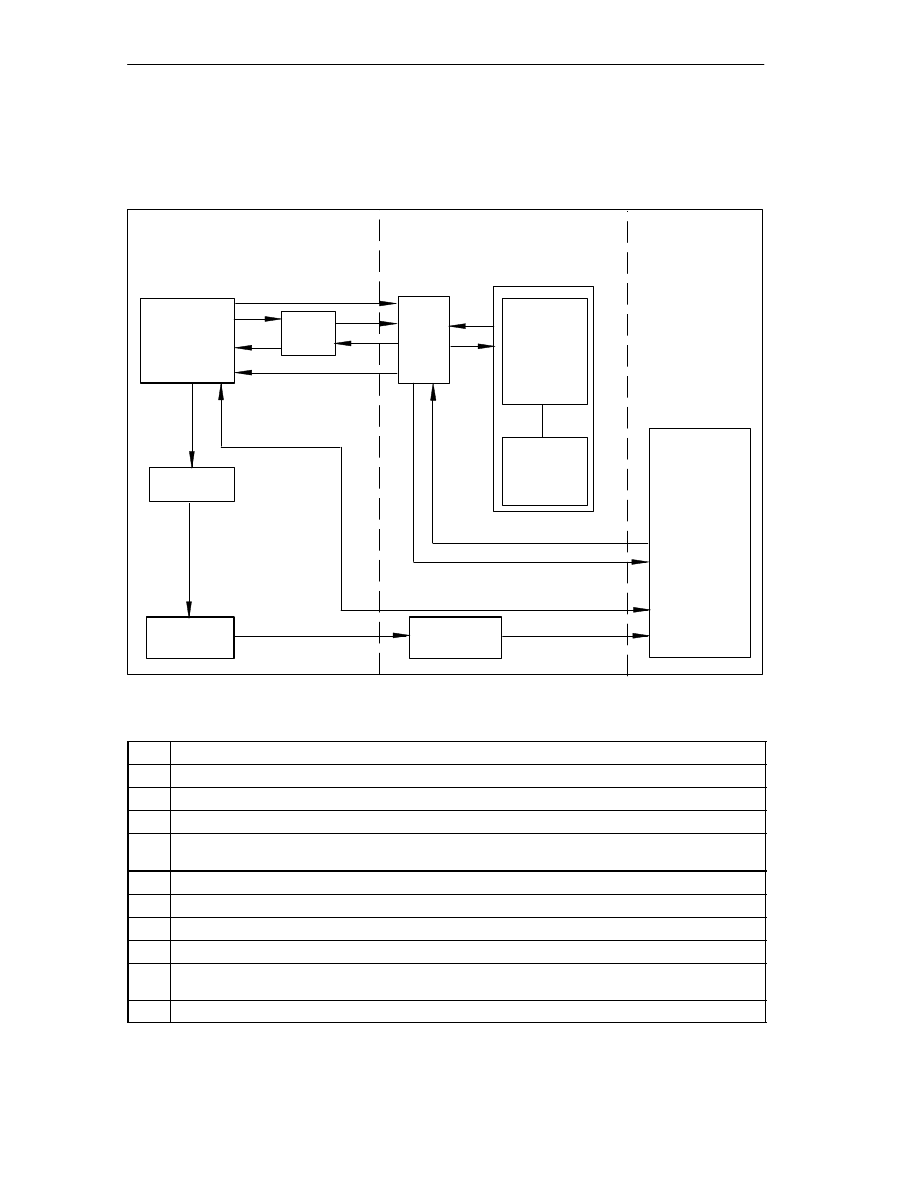
Programming the FM 352
6-20
FM 352 Electronic Cam Controller
C79000-G7076-C352-04
6.9
Parameter Transfer Routes
The term parameter includes the following machine and cam data.
Para. ass.
user interface
HW Config
Parameters
(machine and
cam data)
DB
User
program
CAM_CTRL
1
2
3
4
5
6
7
8
9
10
11
DB
11b
11a
10b
10a
System data
(SDB)
2a
PG/PC
offline
System data
(SDB)
CPU
online
FM 352
Download
Download
Upload to PG
Figure 6-1
Parameter Transfer Routes
1
Save parameters in the parameter assignment user interface.
2
Save HW configuration, compile, and download to CPU.
3
The CPU writes the parameters to the module during system parameter assignment.
4
Upload the parameters of the module to the PG with the “Upload” command.
5
Download parameters from the parameter assignment user interface to the module with the
“Download” command.
6
Write parameters to the module using jobs in the user program.
7
Read parameters from the module using jobs in the user program.
8
Store parameters from the user program in the online DB.
9
Read parameters into the user program from the online DB.
10
Export parameters from the parameter assignment user interface to the DB (offline or online DB);
an offline DB must then also be downloaded to the CPU.
11
Import parameters from an online or offline DB into the parameter assignment user interface.

Programming the FM 352
6-21
FM 352 Electronic Cam Controller
C79000-G7076-C352-04
Typical Situations for the Transfer of Parameters:
1 You edit the parameters with the parameter assignment user interface. The module
must then be assigned the parameters automatically during startup.
Action required: steps 1, 2, 3
2 You modify parameters during startup in the test mode in the parameter
assignment user interface:
Action required: steps 4, 5
3 The parameters modified during installation should be downloaded automatically
during startup:
Action required: steps 1, 2, 3
4 You set the parameters with the parameter assignment user interface. When it
starts up, the module should be assigned parameters only by the user program
using data blocks:
Action required: steps 10, 6
5 You want to create data for recipes:
Action required: step 10
6 You set the parameters with the parameter assignment user interface. These
should be available to the user program for temporary modifications.
Action required: steps 1, 2, 3 for automatic parameter assignment.
Action required: steps 10, 7 for access by the user program.
7 You modify parameters (exclusively) using the user program:
Action required: steps 7, 9, 8, 6
8 You want to see the data modified by the user program in the parameter
assignment user interface.
Action required: step 11
9 The parameters modified by the user program should be downloaded automatically
during startup:
Action required: steps 6, 11, 1, 2, 3

Programming the FM 352
6-22
FM 352 Electronic Cam Controller
C79000-G7076-C352-04

7-1
FM 352 Electronic Cam Controller
C79000-G7076-C352-04
Putting the FM 352 into Operation
Important Note
Please read the points in the following warning carefully.
!
Warning
To prevent injury to personnel and damage to equipment, please note the
following points:
•
Install an EMERGENCY STOP switch in the vicinity of the computer. This is
the only way to ensure that the system can be switched off safely in the event
of a computer or software failure.
•
Install an EMERGENCY STOP limit switch directly connected to the power
units of all drives.
•
Make sure that nobody can obtain access to the area of the system that
contains moving parts.
•
Controlling and monitoring the FM 352 from within your program and from the
Test > Commission dialog at the same time can lead to conflicts with
unforeseeable effects. For this reason, always switch the CPU to STOP when
you work in the Test dialog or deactivate your program.
7

Putting the FM 352 into Operation
7-2
FM 352 Electronic Cam Controller
C79000-G7076-C352-04
Hardware Installation and Wiring
In the first section, you will install the FM 352 in your S7-300 and wire up the front
connector.
Step
What Needs to Be Done?
1
Install the FM 352 (see Chapter 3)
Fit the module in a suitable location.
2
Wire the FM 352 (see chapter 4)
•
Digital inputs on the front connector
•
Digital outputs on the front connector
•
Encoder connection
•
Power supply to the FM 352
3
Check the limit switches relevant for safety
Check that the following are functioning correctly:
•
The limit switches
•
The emergency stop circuits
4
Front connector
The front connector must sit firmly.
5
Check the shielding of each individual cable.
6
Turn on the power supply
Switch the CPU to STOP (safe state).
Turn on the 24 V supply for the FM 352.
Creating a Project
Now set up a project in
STEP 7.
The steps required to set up a project in the SIMATIC Manager are described
below (without using a wizard).
Step
What Needs to Be Done?
1
If you have not already done so, install the parameter assignment user interface.
2
Create a new project in the SIMATIC Manager (File > New).
3
Insert a station in your project (Insert > Station).
4
Select the station and start the configuration user interface ”HW Config” by
double-clicking ”Hardware”.
5
Insert a rack in your hardware configuration with the following:
•
A power supply (PS)
•
CPU/IM 153
•
Function module (FM)
6
Save this hardware configuration in HW Config (Station > Save).

Putting the FM 352 into Operation
7-3
FM 352 Electronic Cam Controller
C79000-G7076-C352-04
Assigning Parameters with the Parameter Assignment User Interface.
If you are putting the module into operation for the first time, assign the parameters
for the module using the parameter assignment user interface. Keep to the
sequence below:
Step
What Needs to Be Done?
1
Select the tier in the rack containing the FM 352 module.
2
Now double-click to start the parameter assignment user interface for the FM 352.
3
Using the menu command File > Properties, you can modify the following settings:
•
General
You can modify the name and enter a comment.
•
Addresses
You can modify the base address and assign the address area to a part process
image. (Note down the module address displayed.)
•
Basic Parameters
You can set the interrupt type and the reaction to a CPU stop.
4
In the block diagram displayed, you can select the dialogs for Axis, Encoders, Cams,
Tracks and Interrupt Enable and set the required parameters.
5
Save the parameter settings with the menu command File > Save.
6
Close the parameter assignment user interface with File > Exit.
7
Save the hardware configuration in HW Config with Station > Save and Compile.
8
Set up an online connection to the CPU and download the hardware configuration to the
CPU. At each change from STOP to RUN, this data is transferred to the FM 352.
9
Select Test > Commission.
Test and Commissioning
You can now test the entries and modifications you have made.
Step
What Needs to Be Done?
1
Check your data with the dialogs Test > Commission, Test > Service and Test > Error
Evaluation.
2
You can modify incorrect machine data in the Test > Commission dialog. These
modifications remain valid until the next STOP-RUN change on the CPU.
3
You can save the corrected machine data on the CPU by repeating steps 7 to 9 of the
previous table.

Putting the FM 352 into Operation
7-4
FM 352 Electronic Cam Controller
C79000-G7076-C352-04
Note
If you use the FM 352 via PROFIBUS-DP; the CPU must be set to RUN or RUN-P
during testing and commissioning. Otherwise, you cannot control the FM 352.
Tests for Axis Synchronization and Switching Behavior
Using the following tests you can check the correct assignment of parameters for
the FM 352.
Step
What Needs to Be Done?
1
Synchronize the axis
•
Incremental Encoders
–
Select ”set reference point”. Enter
the required value
(see Section 9.4).
or
–
Set the function switch “retrigger
reference point” (see Section 9.8).
•
Absolute Encoders
–
The FM 352 is synchronized
immediately after parameter
assignment.
–
Make an absolute encoder
adjustment (see Section 8.4)
You may first have to calculate the
exact value with ”set reference
point”.
Check the actual status of the axis. The actual position must agree with the position
indicated.
2
Check the switching behavior of the cams and tracks being used.
•
Activate the test enable.
•
Run ”set reference point”.
•
Activate cam processing.
•
Enable the track signals.
•
Rotate the encoder or
•
Set the simulation function switch.
3
Test the other settings according to your application
•
Set reference point
•
Set actual value

Putting the FM 352 into Operation
7-5
FM 352 Electronic Cam Controller
C79000-G7076-C352-04
Preparations for Programming
You still need to create the blocks required in your project.
Step
What Needs to Be Done?
1
Select the library FMX52LIB in the SIMATIC Manager (File > Open > Libraries).
2
Copy the functions FC0, FC1 and the channel DB template UDT1 to your blocks folder.
3
Create a channel DB based on the UDT1 template for each module.
4
If you want to use a programmed diagnostic evaluation, copy FC2 and UDT2 and create
a diagnostic DB for each module.
5
If you want to write and read machine data in the user program, you require UDT3 for 16
cams, UDT4 for 32 cams, UDT5 for 64 cams, or UDT6 for 128 cams.
Preparing the Channel DB
Step
What Needs to Be Done?
1
Open the channel DB.
2
Check whether the module address has already been entered in the MOD_ADDR
parameter. If it is not there, it must be entered now.
3
Save the channel DB (File > Save).
Preparing the Diagnostic DB
Step
What Needs to Be Done?
1
Open the diagnostic DB
2
Check whether the module address has already been entered in the MOD_ADDR
parameter. If it is not there, it must be entered now.
3
Save the diagnostic DB (File > Save).
Linking the Functions
Step
What Needs to Be Done?
1
Link the required functions in your user program.
Downloading the Blocks to the CPU
Step
What Needs to Be Done?
1
Select the blocks in the SIMATIC Manager and download them with PLC > Download.

Putting the FM 352 into Operation
7-6
FM 352 Electronic Cam Controller
C79000-G7076-C352-04

8-1
FM 352 Electronic Cam Controller
C79000-G7076-C352-04
Machine Data and Cam Data
Chapter Overview
Section
Contents
Page
8.1
Writing and Reading the Machine and Cam Data
8.2
System of Units
8.3
Machine Data of the Axis
8.4
Absolute Encoder Adjustment
8.5
Machine Data for the Encoder
8.6
Resolution
8.7
Numbers of Cams and Track Data
8.8
Interrupt Enable
8.9
Cam Data
8

Machine Data and Cam Data
8-2
FM 352 Electronic Cam Controller
C79000-G7076-C352-04
8.1
Writing and Reading the Machine and Cam Data
This chapter is relevant if you want to write the parameters directly to the module
using instructions in the user program without using the parameter assignment
user interface.
All the machine and cam data are stored in the parameter DB. You must enter the
number of the parameter DB in the appropriate channel DB.
You can write the parameter DB while working in the parameter assignment user
interface with “Export” and read it with “Import”.
Writing and Activating Machine Data
With the machine data, you adapt the FM 352 to the axis and the encoder.
The machine data are in the parameter DB at addresses 3.1 to 104.0.
Initial Parameter Assignment
If the module does not yet contain machine data (return signal PARA = 0), follow
the steps outlined below to set initial parameters without the parameter assignment
user interface:
•
Enter the new values in the parameter DB.
•
Download the parameter DB to the CPU.
•
Set the following trigger bit in the channel DB:
– Write machine data (MDWR_EN)
•
Call the FC CAM_CTRL function in the cyclic user program.
Changing Machine Data
To change existing machine data (return signal PARA = 1) from the user program,
follow the steps below:
•
Enter the new values in the parameter DB.
•
Set the trigger bits in the channel DB:
– Write machine data (MDWR_EN)
– Activate machine data (MD_EN)
•
Call the FC CAM_CTRL function in the cyclic user program.
•
Check whether the previous cam data are compatible with the modified
machine data.
•
Always write the cam data of the set cams again whether they have been
changed or not (CAM1WR_EN...CAM8WR_EN)

Machine Data and Cam Data
8-3
FM 352 Electronic Cam Controller
C79000-G7076-C352-04
Note
If parameters that are relevant for synchronization were modified, the
synchronization is deleted when the machine data are activated. The settings are
also reset and all the machine and cam data are deleted on the module.
Parameters relevant for synchronization are as follows:
•
Axis type
•
End of rotary axis
•
Encoder type
•
Distance per encoder revolution
•
Increments per encoder revolution
•
Number of revolutions
•
Reference point coordinate
•
Absolute Encoder Adjustment
•
Type of retrigger reference point
•
Direction adaptation
•
Number of Cams
•
Start and end software limit switch
Reading Machine Data
To read the current machine data from the module, follow the steps outlined below:
•
Set the following trigger bit in the channel DB:
– Read machine data (MDRD_EN)
•
Call the FC CAM_CTRL function in the cyclic user program.
This enters the current machine data in the parameter DB on the CPU.
Excerpt from the Channel DB
Address
Name
Type
Initial
Value
Comment
35.0
MDWR_EN
BOOL
FALSE
1 = write machine data
35.1
MD_EN
BOOL
FALSE
1 = activate machine data
37.1
MDRD_EN
BOOL
FALSE
1 = read machine data

Machine Data and Cam Data
8-4
FM 352 Electronic Cam Controller
C79000-G7076-C352-04
Writing Cam Data
With the cam data, you specify the type and action of the cams and their
assignment to the tracks.
Cam data are located in the parameter DB from address 108.0 onwards. They are
grouped in packages each with 16 cams.
Cam data are active immediately after writing.
To write cam data without the parameter assignment user interface, follow the
steps outlined below:
•
Enter the new values in the parameter DB.
•
Download the parameter DB to the CPU.
•
Set the trigger bits in the channel DB (CAM1WR_EN...CAM8WR_EN)
•
Call the FC CAM_CTRL function in the cyclic user program.
Reading Cam Data
To read the current cam data from the module, follow the steps outlined below:
•
Set the following trigger bit in the channel DB:
– Read cam data (CAM1RD_EN ... CAM8RD_EN)
•
Call the FC CAM_CTRL function in the cyclic user program.
This writes the current cam data to the parameter DB on the CPU.
Excerpt from the Channel DB
Address
Name
Type
Initial
Value
Comment
35.3
CAM1WR_EN
BOOL
FALSE
1 = Write cam data 1 (cams 0 to 15)
35.4
CAM2WR_EN
BOOL
FALSE
1 = Write cam data 2 (cams 16 to 31)
35.5
CAM3WR_EN
BOOL
FALSE
1 = Write cam data 3 (cams 32 to 47)
35.6
CAM4WR_EN
BOOL
FALSE
1 = Write cam data 4 (cams 48 to 63)
35.7
CAM5WR_EN
BOOL
FALSE
1 = Write cam data 5 (cams 64 to 79)
36.0
CAM6WR_EN
BOOL
FALSE
1 = Write cam data 6 (cams 80 to 95)
36.1
CAM7WR_EN
BOOL
FALSE
1 = Write cam data 7 (cams 96 to 111)
36.2
CAM8WR_EN
BOOL
FALSE
1 = Write cam data 8 (cams 112 to 127)
37.2
CAM1RD_EN
BOOL
FALSE
1 = Read cam data 1 (cams 0 to 15)
37.3
CAM2RD_EN
BOOL
FALSE
1 = Read cam data 2 (cams 16 to 31)
37.4
CAM3RD_EN
BOOL
FALSE
1 = Read cam data 3 (cams 32 to 47)
37.5
CAM4RD_EN
BOOL
FALSE
1 = Read cam data 4 (cams 48 to 63)
37.6
CAM5RD_EN
BOOL
FALSE
1 = Read cam data 5 (cams 64 to 79)
37.7
CAM6RD_EN
BOOL
FALSE
1 = Read cam data 6 (cams 80 to 95)

Machine Data and Cam Data
8-5
FM 352 Electronic Cam Controller
C79000-G7076-C352-04
Address
Comment
Initial
Value
Type
Name
38.0
CAM7RD_EN
BOOL
FALSE
1 = Read cam data 7 (cams 96 to 111)
38.1
CAM8RD_EN
BOOL
FALSE
1 = Read cam data 8 (cams 112 to 127)
Order when Writing Machine and Cam Data
Always modify machine and cam data in the following order:
•
Write machine data
•
Activate machine data
•
Write cam data
If you set the trigger bits for these jobs all at once, FC CAM_CTRL makes sure
that the jobs are processed in the correct order.

Machine Data and Cam Data
8-6
FM 352 Electronic Cam Controller
C79000-G7076-C352-04
8.2
System of Units
Selecting a Unit
In the parameter assignment user interface of the cam controller, you can select a
specific unit for inputting and outputting data (default: mm).
You can also select the following units:
•
Millimeters, inches, degrees and pulses.
Note
If you change the unit in the parameter assignment user interface, the values are
calculated in the new system. This can lead to rounding errors.
If you change the unit using the machine data, the values are not recalculated
automatically.
If the unit is changed from or to “pulses”, the cam processing is deactivated and
the axis is no longer synchronized.
Units in the Parameter DB
Address
Name
Type
Initial
Value
Comment
8.0
UNITS
DINT
L#0
Units
1 = 10
-3
mm
2 = 10
-4
inches
3 = 10
-4
degrees
4 = 10
-2
degrees
5 = pulses
6 = 10
-3
degrees
Standard Units
In this manual, limit values are always specified in the unit mm. To define the
limits in other systems of units, please make the following calculation:
To convert....
Calculate...
mm
inches
Limit value (inches) = limit value (mm)
0.1
mm
deg
10
-4
(4 decimal places)
10
-3
(3 decimal places)
10
-2
(2 decimal places)
Limit value (degrees) = limit value (mm)
0.1
Limit value (degrees) = limit value (mm)
1
Limit value (degrees) = limit value (mm)
10
mm
pulses
Limit value (pulses) = limit value (mm)
1000
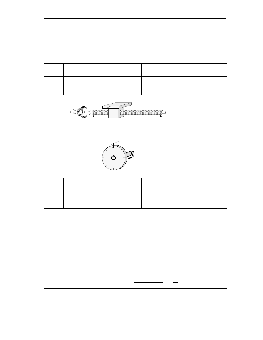
Machine Data and Cam Data
8-7
FM 352 Electronic Cam Controller
C79000-G7076-C352-04
8.3
Machine Data of the Axis
Axis Data
Address
Name
Type
Initial
Value
Comment
12.0
AXIS_TYPE
DINT
L#0
Axis type
0 = Linear axis
1 = Rotary axis
A linear axis is an axis with a limited physical travel range.
Physical start
Physical end
Start of rotary axis = end of rotary axis
A rotary axis is an axis whose travel range is not restricted by mechanical limit stops.
Highest displayed
value
Address
Name
Type
Initial
Value
Comment
16.0
ENDROTAX
DINT
L#100000
End of rotary axis
Range:
1
m to +1 000 000 000
m
The value “end of rotary axis” is the highest theoretical value that the actual value can reach.
The highest theoretical value is however never displayed since it is physically the same position as the
start of the rotary axis (0).
The highest value that can be displayed by a rotary axis is as follows:
End of the rotary axis [
m] – resolution [
m / pulse]
1 [pulse]
Example: End of rotary axis 1000 mm
The display jumps:
•
With a positive direction of rotation from 999 mm to 0 mm.
•
With a negative direction of rotation from 0 mm to 999 mm.
Rotary axis with absolute encoders
With a rotary axis with an absolute encoder the rotary axis range (0 to end of rotary axis) must exactly
cover the total number of encoder steps of the absolute encoder.
End of rotary axis[
m]
number of revolutions(encoder) ·
steps(encoder)[pul]
revolution
·RES
m
pul

Machine Data and Cam Data
8-8
FM 352 Electronic Cam Controller
C79000-G7076-C352-04
Address
Name
Type
Initial
Value
Comment
44.0
REFPT
DINT
L#0
Reference point coordinate
Range:
– 1 000 000 000
m to
+ 1 000 000 000
m
Incremental encoder and initiator:
Using the “Retrigger Reference Point” function switch and a synchronization event specified by the “Type
of Reference Point Retriggering”, the reference point coordinate is assigned to this event.
Absolute encoder (SSI)
An axis with an absolute encoder is always synchronized provided no error is detected (after transfer of the
first error-free SSI frame).
Read the description of absolute encoder adjustment in Section 8.4 (Page 8-12), explaining the
interaction of absolute encoder adjustment with other data.
Linear axis
The value of the reference point coordinate must be within the working range (including the start
software limit switch and end software limit switch).
Rotary axis
The value of the reference point coordinate must be greater than or equal to 0 and must be less than the
value “end of rotary axis” “ (0
reference point coordinate < “end of rotary axis”).
Address
Name
Type
Initial
Value
Comment
52.0
RETR_TYPE
DINT
L#0
Type of reference point retriggering:
Ranges:
0 = Ref. point switch and zero marker direction +
1 = Ref. point switch and zero marker direction –
6 = Only ref. point switch
7 = Only zero marker
With “type of reference point retriggering”, you specify the conditions for synchronizing the axis when
working with an incremental encoder or an initiator (see also Section 9.8, Page 9-19)
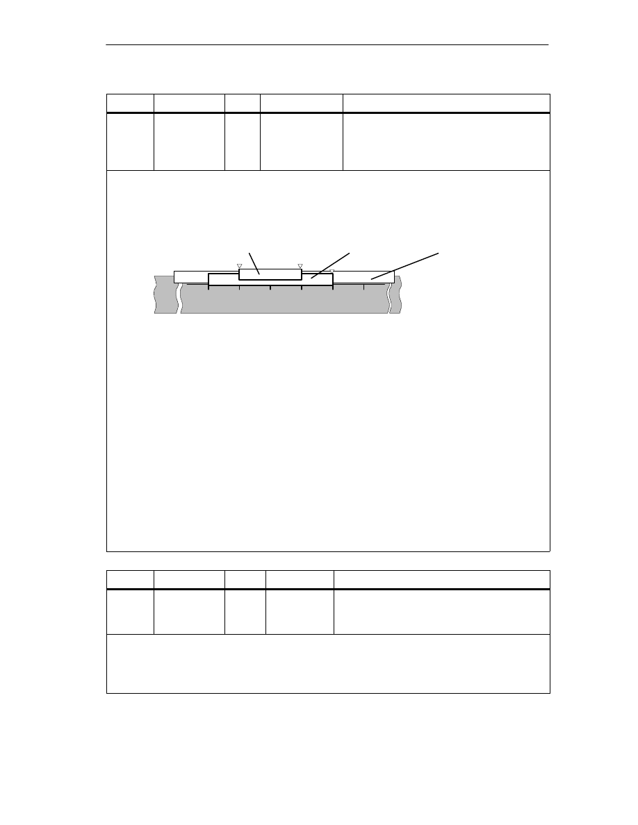
Machine Data and Cam Data
8-9
FM 352 Electronic Cam Controller
C79000-G7076-C352-04
Address
Name
Type
Initial Value
Comment
64.0
68.0
SSW_STRT
SSW_END
DINT
DINT
L# –100 000 000
L# 100 000 000
Start software limit switch
End software limit switch
Range:
– 1 000 000 000
m to 1 000 000 000
m
ÉÉÉÉÉÉÉÉÉÉÉÉÉÉÉ
ÉÉÉÉÉÉÉÉÉÉÉÉÉÉÉ
This axis data is only of significance with a linear axis.
The software limit switches are active when the FM 352 is synchronized. The range set by the software
end limit switch is known as the working range. The limits of the working range can be monitored by the
FM 352.
The start software limit switch (SLS) must always be less than the end software limit switch (SLE).
Absolute encoder (SSI)
The FM 352 is synchronized after you have received a complete error-free frame. The software limit
switches are monitored from this point in time.
The absolute encoder which you use must at least cover the working range (from software limit switch
start to software limit switch end).
Incremental encoder and initiator
After starting up the FM 352, the axis is initially not synchronized. The software limit switches are only
monitored after synchronization.
Relationship: working range, encoder range, travel range
•
The “working range” is the range you specify for your task using the software limit switches.
•
The “encoder range” is the range covered by the encoder. With a linear axis, this is placed
symmetrically over the working range by the module; in other words, the module shifts the encoder
range so that the distances between the software limit switches and the ends of the encoder range
are the same (see figure).
•
The “travel range” is the range of values that can be processed by the FM 352. It is dependent on
the resolution.
0
300
-100
Axis
ÈÈÈÈÈÈÈÈÈ
ÈÈÈÈÈÈÈÈÈ
Working range
ÍÍÍÍÍ
ÍÍÍÍÍ
Encoder range
Travel range
SLS
SLE
The following rule applies:
Travel range
≥
encoder range
≥
working range
Address
Name
Type
Initial Value
Comment
80.0
HYS
DINT
L#0
Hysteresis
Ranges:
0...65.535 [pul]
resolution [
m
/
pul
]
The range of values depends on the resolution
:
The maximum value that can be input is as follows:
–
For linear axes: maximum input value <
¼
of the working range
–
For rotary axes: maximum input value <
¼
of the rotary axis range
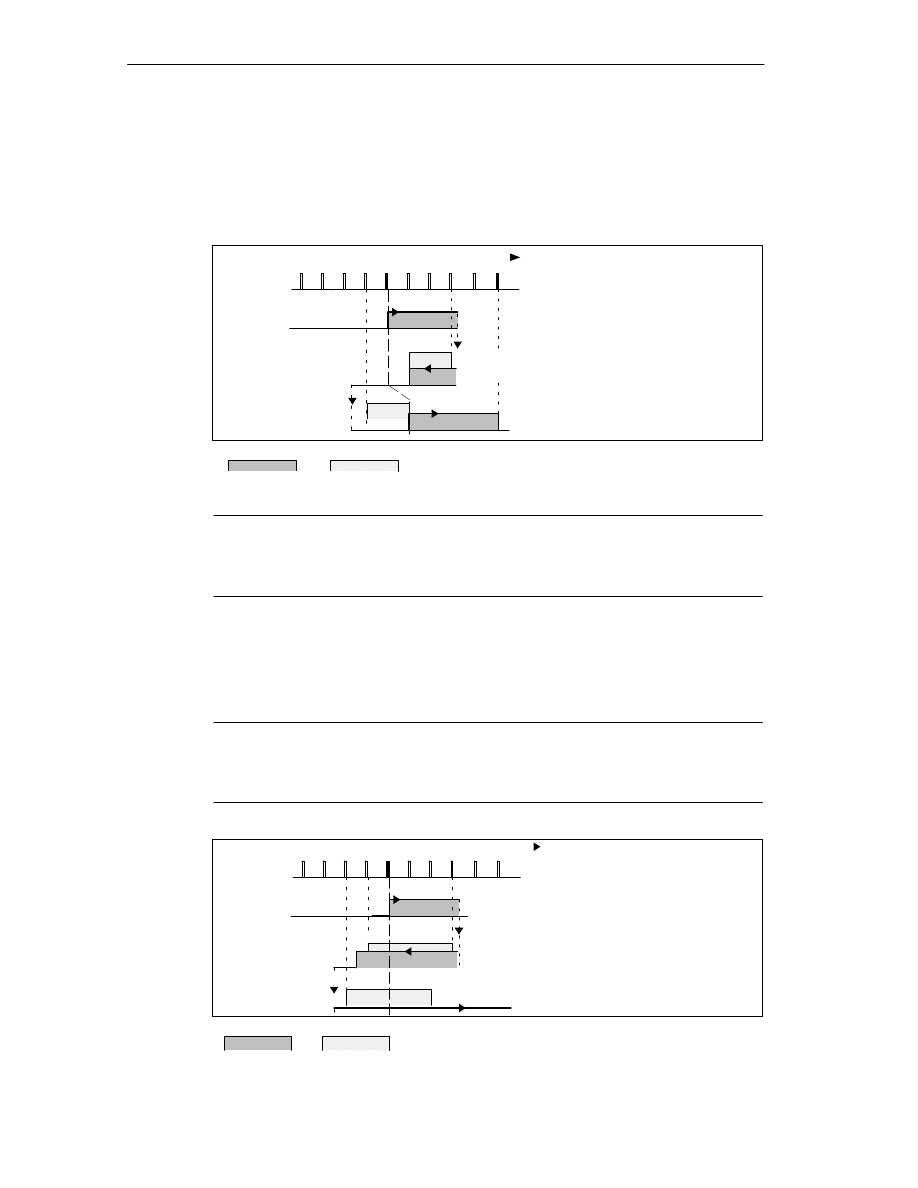
Machine Data and Cam Data
8-10
FM 352 Electronic Cam Controller
C79000-G7076-C352-04
Distance Cams and Hysteresis
A distance cam is activated in the following situation:
•
the detected actual value is within the distance cam and
•
no hysteresis is active.
The switching point can vary depending on to the position of the direction change.
Activation direction
2 3
4 5
6
7
8
9 10
Change of
direction
CS
CE
Change of
direction
Cam
Hysteresis
1)
Cam is activated since the cam
start is reached in the positive
activation direction
Cam remains active despite
new direction due to hysteresis
2)
3)
4)
5)
1)
Cam is deactivated at the end
of the hysteresis
Cam remains deactivated after
the change in direction
Cam is activated again at the
end of the hysteresis
2)
3)
4)
5)
Figure 8-1
Activation of a Distance Cam with Hysteresis
Note
Distance cams that are shorter than the hysteresis can be hidden by the
hysteresis when there is a change in direction.
Time Cams with Hysteresis
A time cam is activated in the following situation:
•
the cam start is reached in the activation direction and
•
no hysteresis is active.
Note
If the range between the reversal point and the start of the time cam is less than
the hysteresis, the time cam will be “hidden” by the hysteresis.
Figure 8-2 illustrates a time cam that is not activated again.
2 3
4 5
6 7
8 9 10
Change of
direction
Change of
direction
CS
Cam
Hysteresis
Activation direction
1)
Cam is activated since the cam
start is passed in the
positive activation direction
After the change in direction,
the cam remains active until the
on time has expired regardless
of the hysteresis
2)
3)
Cam start is hidden by the
hysteresis, the cam is not
activated
3)
2)
1)
Figure 8-2
Activation of a Time Cam with Hysteresis

Machine Data and Cam Data
8-11
FM 352 Electronic Cam Controller
C79000-G7076-C352-04
Address
Name
Type
Initial
Value
Comment
84.0
SIM_SPD
DINT
L#0
Simulation Speed
The simulation speed depends on the
resolution.
0 = stationary
5
⋅
10
8
=
Highest possible setting of the
module
Within this range, the simulation speed
depends on the resolution:
1000
resolution
≤
simulation speed
≤
3
10
7
resolution
This machine data specifies the simulation speed for simulation (see Chapter 9). The actual simulation
speed V
sim
can deviate from the entered simulation speed V
sim, V
and is calculated according to the
following formula:
(
V
sim
=
6
10
7
RES
integer
6
10
7
RES
V
sim,V:
)
In this formula
•
V
sim
: Simulation speed set by the FM 352, unit:
m
/
min
.
•
V
sim,V
: Simulation speed specified in the machine data, unit:
m
/
min
.
•
RES: Resolution calculated from the encoder data, unit:
m
/
pulse
•
Integer (): from this expression, only the value before the decimal point is used for further
calculation. This expression must be within the range 2 ... 65536 for all calculations.
As a result of the relationships (see formula), the actual simulation speed changes abruptly.
Address
Name
Type
Initial
Value
Comment
4.0
EDGEDIST
DINT
L#0
Minimum edge-to-edge distance
Range:
0 ... 1 000 000 000
m
With this machine data, you define a range after detection of the start of measurement when using edge
detection. If the end of the measurement is within this range, the measurement is rejected.
The start of the measurement is signaled only after the minimum edge-to-edge distance has been
traveled.

Machine Data and Cam Data
8-12
FM 352 Electronic Cam Controller
C79000-G7076-C352-04
8.4
Absolute Encoder Adjustment
Definition
With absolute encoder adjustment and the reference point coordinate, there is a
defined correlation between the encoder range of values and the axis coordinate
system.
Address
Name
Type
Initial Value
Comment
48.0
ENC_ADJ
DINT
L#0
Absolute encoder adjustment
Range:
0 to (2
25
–1)
“Absolute encoder adjustment” finds the encoder value corresponding to the reference point coordinate
on the axis. The value must be less than the total number of steps of the absolute encoder.
Establishing the Correct Absolute Encoder Adjustment
After initial parameter assignment, further steps are necessary to establish the
correct relationship between encoder and coordinate system. The sequence shown
below is the sequence when using the parameter assignment user interface.
1. Move the axis to a defined reproducible point that you know and that is
physically unique.
This could be, for example,the “end software limit switch”.
2. Start “set reference point” with the coordinate of the point defined in step 1.
The FM 452 now determines an encoder value, the absolute encoder
adjustment, for the reference-point coordinate entered in the machine data. You
can read out this value with the user interface in the service dialog.
3. Enter the read-out value in the machine data “absolute encoder adjustment“.
4. Save the machine data.
5. Download the data in HW Config to the CPU.
6. To activate the data, run a warm restart on the CPU.
Note
You make this adjustment once during installation and startup. The FM 452 is
synchronized following parameter assignment during startup as soon as a
complete, error-free frame is received from the encoder following startup.
Data in the Parameter DB
Address
Name
Type
Initial Value
Comment
44.0
REFPT
DINT
L#0
Reference point coordinate
Range:
– 1 000 000 000
m to
+ 1 000 000 000
m

Machine Data and Cam Data
8-13
FM 352 Electronic Cam Controller
C79000-G7076-C352-04
Example of Absolute Encoder Adjustment
In the example, the following is assumed:
•
Reference-point coordinate = -125 mm
•
Working range of SSW_STRT = – 1000 mm to SSW_END = 1000 mm
•
Absolute encoder adjustment = 0
•
Encoder range = 2048 increments (= pulses) with a resolution of
1 mm/pulse
•
The absolute encoder used cannot be exactly adjusted mechanically and also
does not have the option of setting the actual value.
Axis
–1000
0
V
alue of absolute encoder
2047
–125
Axis
–1000
1000
0
–125
Encoder value 0
Instantaneous
Encoders
Desired
1)
2)
1) Correlation between the coordinate system and the encoder values with the set absolute
encoder adjustment. The encoder value 0 corresponds to the actual value -125.
Required correlation of the coordinate system with the encoder. At this position the
coordinate should be -125.
2)
0
Actual value
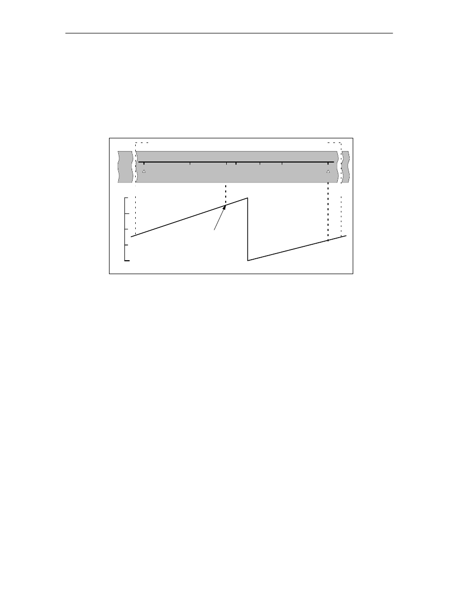
Machine Data and Cam Data
8-14
FM 352 Electronic Cam Controller
C79000-G7076-C352-04
Result After Setting the Reference Point
After setting the reference point, the relationship between the encoder and
coordinate system is as follows:
The reference point coordinate on the axis (-125) is assigned to the encoder value
(1798) calculated from the absolute encoder adjustment.
SLE
SLS
Axis
–1000
1000
0
V
alue of absolute encoder
0
2047
REF
–125
1798
Value from absolute
encoder adjustment
875
Encoder range covered by this encoder
1024
–1023
0
The encoder supplies 2048 defined values. The working range is defined by the
software limit switches. Due to the selected resolution of 1 mm per pulse, the
encoder can, however, cover a larger working area than intended with the software
limit switches.
With the set resolution the working range is already covered with 2001 values.
Therefore, in the example there are 47 pulses “left over” which lie symmetrically
about the working range.
Alternative: Mechanical Adjustment of an Encoder
You can obtain a correct relationship between the coordinate system and the
encoder as follows:
1. Move the axis to a reproducible position (for example the start software limit
switch).
2. Enter this coordinate value in the machine data as the reference point
coordinate.
3. Read the encoder value displayed at this position in the service dialog of the
user interface.
4. Enter this value as the absolute encoder adjustment in the machine data.
A correct actual value is then always displayed after parameter assignment.
Instead of steps 3. and 4., you can also set the encoder to zero with “Reset” (if this
exists) and enter the value “0” as the absolute encoder adjustment in the machine
data.

Machine Data and Cam Data
8-15
FM 352 Electronic Cam Controller
C79000-G7076-C352-04
8.5
Machine Data of the Encoder
Definition
The encoder supplies position information to the module; the module evaluates this
information taking into account the resolution and calculates an actual value.
You can only be sure that the calculated actual value of the axis position matches
the actual axis position when the information in the machine data of the encoder is
correct.
Data in the Parameter DB
Address
Name
Type
Initial Value
Comment
20.0
ENC_TYPE
DINT
L#1
Encoder type and frame length
Range of values:
1 = 5 V incremental
2 = 24 V incremental
3 = SSI 13-bit frame length
4 = SSI 25-bit frame length
5 = listen in
6 = 24 V initiator forwards
7 = 24 V initiator backwards
8 = SSI 13-bit (right-justified)
9 = SSI 25-bit (right-justified)
10 = listen in (right-justified)
With the “frame length”, you specify the clock frame output by the FM 352.
If you select “listen in”, you turn off the clock of the FM 352. The FM 352 can then listen in on other
SSI frames with a 13 or 25-bit frame length. The transmission rate depends on the cycle rate of the
master module.
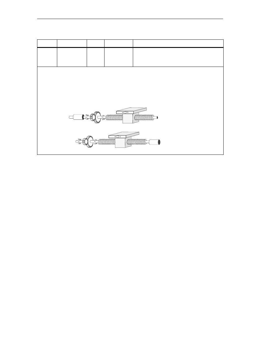
Machine Data and Cam Data
8-16
FM 352 Electronic Cam Controller
C79000-G7076-C352-04
Address
Name
Type
Initial Value
Comment
24.0
DISP_REV
DINT
L#80000
Distance per encoder revolution
Range of values:
1
m to 1.000.000.000
m
With the machine data “distance per encoder revolution” you inform the FM 352 of the distance
covered by the drive system per encoder revolution.
The value “distance per encoder revolution” depends on how the axis is set up and how the encoder is
installed. You must take into account all transmission components such as couplings or gearing.
Section 8.6 (Page 8-20) describes the relationship between the machine data “distance per Encoder
Revolution” and “increments per encoder revolution”.
Motor
Encoder
Gearing
Motor
Encoder
Gearing

Machine Data and Cam Data
8-17
FM 352 Electronic Cam Controller
C79000-G7076-C352-04
Address
Name
Type
Initial Value
Comment
32.0
INC_REV
DINT
L#500
Increments per encoder revolution
Range of values:
1 to 2
25
Note
:
If you are using pulses as the unit, this entry has
no significance.
The “increments per encoder revolution” machine data specifies the number of increments output by an
encoder per revolution. Based on this value and the machine data “distance per encoder revolution”, the
FM 352 can calculate the resolution.
Incremental encoder
Any value from the range shown can be entered. One increment involves quadruple evaluation by the
module (see also Section 10.1, Page 10-2).
Initiator
Any value from the range shown can be entered.
Absolute encoder
The limits vary according to the type of encoder.
Note:
The number of pulses of an encoder is calculated from the machine data “increments per encoder
revolution” multiplied by “number of revolutions” (see page 8-20).
Encoder Type
Frame Length / Type
Value Range
Can be used as
linear axis
Single-turn
Single-turn
Single-turn
Multi-turn
Multi-turn
Listen-in
Listen-in
Multi-turn as
Single-turn
Special setting:
13-bit half fir tree
13-bit right-justified
25-bit right-justified
25-bit fir tree
25-bit right-justified
Fir tree
right-justified
64 ... 8192 in powers of 2
64 ... 8192 all values
64 ... 2
25
all values
64 ... 8192 in powers of 2
64 ... 2
24
all values
64 ... 8192 in powers of 2
64 ... 2
25
all values
25-bit half fir tree
64 ... 8192 in powers of 2
X
X
X

Machine Data and Cam Data
8-18
FM 352 Electronic Cam Controller
C79000-G7076-C352-04
Address
Name
Type
Initial Value
Comment
36.0
NO_REV
DINT
L#1024
Number of encoder revolutions
Range of values:
1 (single-turn encoder)
2 to 2
19
(multi-turn encoder)
The machine data “number of encoder revolutions” is only necessary for absolute encoders. You use it
to define the number of revolutions possible with this encoder. For more information on absolute
encoders, read Chapter 10.3 in this manual.
Single-turn encoders
Only the value 1 is possible.
Multi-turn encoders
Multi-turn / Listen-in (fir tree):
2 ... 4096 in powers of 2.
Multi-turn / listen-in (right-justified):
2 ... 2
19
All values with the following restriction:
Increment/encoder revolution
number of encoder revolutions
≤
2
25
.
Linear measure
You can also connect a linear measure by entering the value 1.
Total number of steps of the encoder
The total number of steps is not part of the machine data.
Total no. of steps = increments per encoder revolution
no. of revolutions
Address
Name
Type
Initial Value
Comment
40.0
BAUDRATE
DINT
L#0
Baud rate
Range of values: 0 = 125 kHz
1 = 250 kHz
2 = 500 kHz
3 = 1000 kHz
With the baud rate machine data, you define the speed of the data transfer from SSI encoders to the
FM 352.
This entry has no significance for incremental encoders.
The maximum cable length depends on the baudrate:
•
125 kHz
320 m
•
250 kHz
160 m
•
500 kHz
63 m
•
1000 kHz
20 m

Machine Data and Cam Data
8-19
FM 352 Electronic Cam Controller
C79000-G7076-C352-04
Address
Name
Type
Initial Value
Comment
59.0
CNT_DIR
BOOL
FALSE
Count direction
0 = normal
1 = inverted
With the machine data “count direction”, you match the direction of the position detection to the direction
of axis movement.
You must also take into account all the directions of rotation of the transmission elements (for example
coupling and gearing).
•
Normal = ascending count pulses (incremental encoder) or encoder values (absolute encoder)
correspond to ascending actual position values
•
Inverted = ascending count pulses (incremental encoder) or encoder values (absolute encoder)
correspond to descending actual position values.
A lead time in conjunction with an absolute encoder (SSI) and inverted count direction is not
permitted.
Address
Name
Type
Initial Value
Comment
63.0
63.1
63.2
MON_WIRE
MON_FRAME
MON_PULSE
BOOL
BOOL
BOOL
TRUE
TRUE
TRUE
Monitoring
1 = wire break
1 = frame error (must always be 1)
1 = missing pulses
Wire break
When monitoring is activated, the FM 352 monitors the signals A, A, B, B, N and N of an incremental
encoder. The monitoring detects:
•
Wire break
•
Short circuit on individual lines.
With incremental encoders without a zero marker, you must either
–
deactivate the wire break monitoring or
–
connect the signals N and N externally (see Section 10.1)
•
Edge-to-edge distance between the edges of the counted pulses.
•
Failure of the encoder power supply.
Frame error
The frame error monitoring for absolute encoders (SSI) cannot be deactivated. It monitors the frame as
follows:
•
Start and stop bit errors
•
Monitoring of the monostable flip-flop period of the connected encoder
Missing pulses (incremental encoder)
An incremental encoder must always supply the same number of increments between two consecutive
zero markers.
The FM 352 checks whether the zero marker of an incremental encoder occurs at the correct encoder
status.
For encoders without zero markers, you must deactivate error pulse monitoring. You must also
deactivate wire break monitoring or connect the zero marker inputs N and N externally.

Machine Data and Cam Data
8-20
FM 352 Electronic Cam Controller
C79000-G7076-C352-04
8.6
Resolution
Definition
The resolution is a measure of the accuracy of cam processing. It also determines
the maximum possible travel range.
The resolution (RES) is calculated as shown in the following table:
Incremental Encoders
Absolute Encoders/Initiators
Input values
•
Distance per encoder revolution
•
Increments per encoder
revolution
•
Pulse evaluation: quadruple
•
1 increment = 4 pulses
•
Distance per encoder revolution
•
Increments per encoder
revolution
•
1 increment = 1 pulse
Calculation
RES
distance
encoder rev
RES
encoder rev
pulses
encoder rev
Note
In the pulses system of units, the resolution always has the value 1.
All position information is rounded up to the integral multiple of the resolution. This
allows you to distinguish between the entered and the used values.

Machine Data and Cam Data
8-21
FM 352 Electronic Cam Controller
C79000-G7076-C352-04
Range of Values of the Resolution
The range for the resolution must be converted to the basic system of units. The
resolution must be kept within this range by selecting the values “distance per
encoder revolution” and “increments per encoder revolution”.
Based on the systems of units, the ranges for the resolution are as follows:
System of
Units
Specifications
in...
Range for the Resolution
mm
10
–3
mm
0.1
10
–3
mm .... 1000
10
–3
mm/pulse
inches
10
–4
inches
0.1
10
–4
inch .... 1000
10
–4
inches/pulse
degrees
10
–4
degrees
10
–3
degrees
10
–2
degrees
0.1
10
–4
degrees .... 1000
10
–4
degrees/pulse
0.1
10
–3
degrees .... 1000
10
–3
degrees/pulse
0.1
10
–2
degrees .... 1000
10
–2
degrees/pulse
Pulses
1 pulse
1
Example
•
An incremental encoder has the following data:
– Increments per encoder revolution: 5000
– Distance per encoder revolution: 1000 mm
– 1 increment = 4 pulses
This results in the following resolution (quadruple evaluation):
Resolution
1000 mm
=
5000 increments
= 0.2000
mm
increment
4 pulses
=
mm
0.0500
pulse
mm
=
0.2000
•
An SSI encoder has the following data:
– Increments per encoder revolution: 4096
– Distance per encoder revolution: 1000 mm
– 1 increment = 1 pulse
This results in the following resolution:
Resolution
1000 mm
=
4096 increments
= 0.2441
mm
increment
pulse
mm
= 0.2441

Machine Data and Cam Data
8-22
FM 352 Electronic Cam Controller
C79000-G7076-C352-04
Relationship Between Travel Range and Resolution
The travel range is limited by the numeric representation in the FM 352. The
number representation varies depending on the resolution. Therefore, make sure
that you are always within the permitted limits when specifying values.
The maximum travel range is represented in the table below:
Resolution (RES) is in the range
Maximum travel range
0.1
m
/
pulse
RES < 1
m
/
pulse
–10
8
m to 10
8
m (–100 m to + 100 m)
1
m
/
pulse
RES
1000
m
/
pulse
–10
9
m to 10
9
m (–1000 m to + 1000 m)
Relationship Between Feedrate and Resolution
The feedrate displayed can be within the following limits depending on the
resolution (this information relates to units of millimeters):
•
from 1
m
/
min
to 90
m
/
min
at a resolution of
1
m
/
pulse
•
from 1
m
/
min
to 900
m
/
min
at a resolution of
1
m
/
pulse
The speed is calculated and filtered by the module every 4 ms.
It has at least an inaccuracy of one pulse/4 ms and is not suitable for closed-loop
control.

Machine Data and Cam Data
8-23
FM 352 Electronic Cam Controller
C79000-G7076-C352-04
8.7
Number of Cams and Track Data
Number of Cams
The number of cams determines the cam cycle time and the maximum number of
cams that can be set.
Number of Cams
Cam Cycle Time
16 cams
20.48
s
32 cams
40.96
s
64 cams
81.92
s
128 cams
163.84
s
Number of Cams in the Parameter DB:
Address
Name
Type
Initial Value
Comment
76.0
C_QTY
DINT
UDT3: L#0
UDT4: L#1
UDT5: L#2
UDT6: L#3
Number of cams:
0 = max. 16 cams
1 = max. 32 cams
2 = max. 64 cams
3 = max. 128 cams
Track Data in the Parameter DB
Address
Name
Type
Initial Value
Comment
90.0
TRACK_OUT
WORD
W#16#0
Activation of the track outputs
Range:
0 = cam controller
1 = CPU
Bit number = track number
Bits 13 to 15 must be 0.
With the machine data “activation of the track outputs”, you specify how the track signals of tracks
0 to 12 are activated. Activation is possible via:
•
Cam controller: The track signals are activated and deactivated by the cam processing of the
FM 352.
•
CPU: The track signals represent the corresponding values of the track enables in the channel
DB.
This means that the track outputs can be activated specifically from within your program.

Machine Data and Cam Data
8-24
FM 352 Electronic Cam Controller
C79000-G7076-C352-04
Address
Name
Type
Initial Value
Comment
95.0
EN_IN_I3
BOOL
FALSE
Enable input
1 = track signal track 3 is ANDed with enable
input I3
Bits 95.1 to 95.7 must be 0.
The track signal Q3 is activated in the following situation:
•
the track is enabled with TRACK_EN and
•
the appropriate external enable input I3 is set and
•
the track result of the track is 1.
Address
Name
Type
Initial Value
Comment
99.0
99.1
99.2
SPEC_TRC0
SPEC_TRC1
SPEC_TRC2
BOOL
BOOL
BOOL
FALSE
FALSE
FALSE
Special tracks
1 = track 0 is counter cam track
1 = track 1 is counter cam track
1 = track 2 is brake cam track
You can set tracks 0, 1 and 2 as special tracks.
Address
Name
Type
Initial Value
Comment
100.0
104.0
CNT_LIM0
CNT_LIM1
DINT
DINT
L#2
L#2
Upper counter value counter cam track
(track 0)
Upper counter value counter cam track
(track 1)
Range:
2 ... 65535
With this machine data, you specify the upper counter value for the set counter cam track.

Machine Data and Cam Data
8-25
FM 352 Electronic Cam Controller
C79000-G7076-C352-04
8.8
Interrupt Enable
Definition
In the cam data, you can specify where the hardware interrupts are generated
when cams 0 to 7 are activated and/or deactivated (see Section 8.9, Page 8-26).
Machine Data for Interrupt Enable in the Parameter DB
Address
(abs)
Name
Type
Initial Value
Comment
3.2
PI_CAM
BOOL
FALSE
1 = enable hardware interrupt: cam on/off
Cam Data for Interrupt Enable in the Parameter DB
Address
(rel)
Name
Type
Initial Value
Comment
+0.4
PI_SW_ON
BOOL
FALSE
1 = hardware interrupt on activation
+0.5
PI_SW_OFF
BOOL
FALSE
1 = hardware interrupt on deactivation
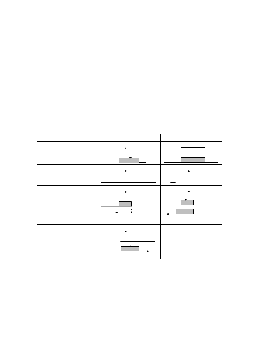
Machine Data and Cam Data
8-26
FM 352 Electronic Cam Controller
C79000-G7076-C352-04
8.9
Cam Data
Definition
Cam data describe the characteristics of a cam, the assignment of each cam to a
track, and the switching behavior of the cam. The cam data listed below are set for
each individual cam.
•
Only the cams you set as “true” will be interpreted and processed by the
module.
•
Cams 0 to 7 have process interrupt capability.
•
The number of cams that can be set depends the number available.
Switching Response of Cams Dependent on the Activation Direction.
With the exception of example 5, the positive activation direction is assumed.
No.
Description
Distance cam
Time cam
1
A cam is passed in the
activation direction
CS
CE
CS
On time
activation direction
2
A cam is passed in the
direction opposite to the
CS
CE
CS
On time
direction o
osite to the
activation direction
3
A cam is approached in the
activation direction; while
the cam is active, the
direction of the axis is
CS
CE
CS
x
On time
t1
direction of the axis is
changed.
On time x = t1 + t2
t2
t1
4
A cam is approached in the
direction opposite to the
activation direction; the
CS
CE
Cam not switched
activation direction the
direction of travel of the axis
changes to the activation
direction at the cam
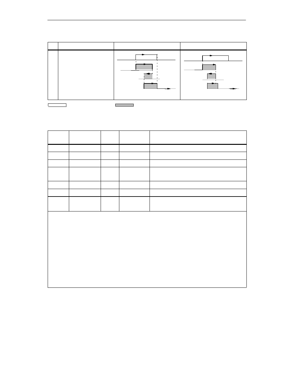
Machine Data and Cam Data
8-27
FM 352 Electronic Cam Controller
C79000-G7076-C352-04
No.
Time cam
Distance cam
Description
5
A cam is approached and
left in any direction; both
directions are set as the
activation direction.
CS
CE
CS
x
t1
On time
t2
t3
On time x = t1 + t2 + t3
Set cam
Switched cam
Cam Data in the Parameter DB
Address
(relative)
Name
Type
Initial Value
Comment
+0.0
CAMVALID
BOOL
FALSE
1 = cam valid
+0.1
EFFDIR_P
BOOL
TRUE
1 = activation direction positive (plus)
+0.2
EFFDIR_M
BOOL
TRUE
1 = activation direction negative (minus)
+0.3
CAM_TYPE
BOOL
FALSE
0 = distance cam
1 = time cam
+0.4
PI_SW_ON
BOOL
FALSE
1 = hardware interrupt on activation
+0.5
PI_SW_OFF
BOOL
FALSE
1 = hardware interrupt on deactivation
+1.0
TRACK_NO
BYTE
B#16#0
Track number
Range:
0 to 31
Note:
Unused cams should always be set to “invalid” (CAMVALID = FALSE).
Activation direction
Two activation directions are possible:
positive: The cam is activated at the cam start when the axis is moving in the direction of ascending
actual values.
negative: The cam is activated at the cam end when the axis is moving in the direction of
descending actual values.
You can also set both activation directions at the same time.
Track number
With the track number, you define the track with which each cam is effective.
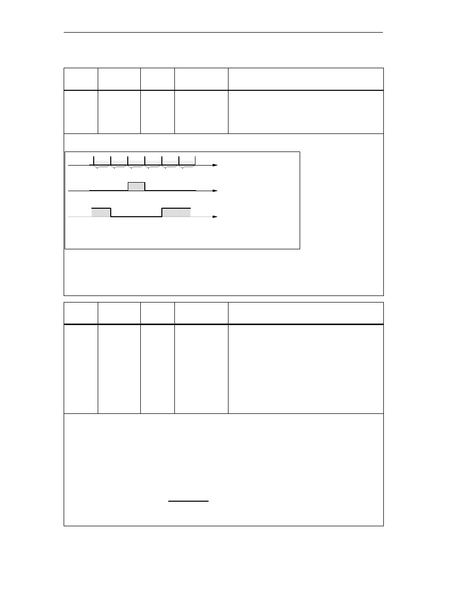
Machine Data and Cam Data
8-28
FM 352 Electronic Cam Controller
C79000-G7076-C352-04
Address
(relative)
Name
Type
Initial Value
Comment
For distance cams
+2.0
+6.0
CBEGIN
CEND
DINT
DINT
L#–100000000
L#100000000
Cam start (CS)
Cam end (CE)
Range:
– 1 000 000 000
m to 1 000 000 000
m
The inactive part of a cam must always have a minimum clearance of four pulses between the cam end
(CE) and cam start (CS).
If CE = CS, the cam is activated for one pulse
.
Minimum Length of a Distance Cam
CE
CS
Pulses; calculated from
the encoder signals
Shortest cam
CS = 103 and CE = 103
Shortest non–active
cam, when CS is
greater than CE:
CS = 105 and CE = 101
101 102 103 104 105
CS = CE
s
s
CS = cam start; CE = cam end
106
Figure 8-3
Shortest Cam with the Axis Moving in the Positive Direction
Address
(relative)
Name
Type
Initial Value
Comment
For time cams
+2.0
+6.0
CBEGIN
CEND
DINT
DINT
L#–100000000
L#100000000
Cam start (CS)
Cam end (CE)
On Time
Range:
(0 to 13421)
100
s with a maximum of 16 cams
(0 to 26843)
100
s with a maximum of 32 cams
(0 to 53686)
100
s with a maximum of 64 cams
(0 to 65535)
100
s with a maximum of 128
cams
With a time cam, you specify a cam start and an “on time” instead of a cam end. You can specify the on
time in increments of 100
s. The time starts to run when the cam is activated.
The following conditions apply for specifying the times
•
0
s: A cam with the on time 0
s is never activated.
•
0
s < t
400
s: The FM 352 sets a minimum cam time of approximately 330
s.
•
t > 400
s: The FM 352 calculates the actual on time
t
act
from the specified on time
t
spec
according to
the following formula:
(
t
act
=
*
Cam cycle time
integer
t
spec
cam cycle
)
The maximum error is always less than one cam cycle period.

Machine Data and Cam Data
8-29
FM 352 Electronic Cam Controller
C79000-G7076-C352-04
Address
(relative)
Name
Type
Initial Value
Comment
+10.0
LTIME
INT
0
Lead Time
Range:
(0 to 53686)
100
s with a maximum of 16 cams
(0 to 65535)
100
s with a maximum of 32, 64 or
128 cams
Delays in the connected switching elements can be compensated by specifying a lead time. You enter
the lead time in steps of 100
s. You can assign a lead time for each cam. The lead time applies to the
cam start and cam end.
Lead Distance
The lead distance of a cam is recalculated depending on the current feedrate and the lead time. The
entire cam is shifted in the direction of the actual value by this distance. The range set is known as the
“static range” and the range calculated based on the lead time is known as the “dynamic range”.
Lead distance = lead time
current feedrate.
Calculation of the lead distance of all cams is made within 1/4 of the longest set lead time on the
FM 352. If you set a very high lead time for a cam, the dynamic adjustment is calculated less often.
Actual Lead Time
You can calculate the actual lead time as follows:
Calculate the cam cycle time: This is the time in which the FM 352 has completely processed all
cams and depends on the number of cams in use (see table Page 8-23).
Calculate the actual lead time with the following formula:
Where:
Lead time
act
is the lead time set by the FM 352
Lead time
L
is the lead time you specified.
Integer () means that in the calculation inside the brackets, only the value before the decimal point is
taken into account.
The maximum error of the lead time
act
is always less than the cam cycle time
4.
Example:
The following values are specified:
Number of cams: maximum of 32 cams
cam cycle time: 40.96
µ
s
lead time
I
= 1000
µ
s
Result: You obtain an actual lead time of 983
µ
s.
A lead time in conjunction with an absolute encoder (SSI) and inverted count direction is not
permitted.
Lead time
act
= integer
(
Cam cycle time
4
Lead time
I
Cam cycle time
4
)
Note
The actual lead time is always less than the set lead time. It can be 0 even though
the set lead time is
100
s.
The lead distance on a rotary axis must be less than the rotary axis range and the
non-active part of the cam. This must be guaranteed for all speeds.
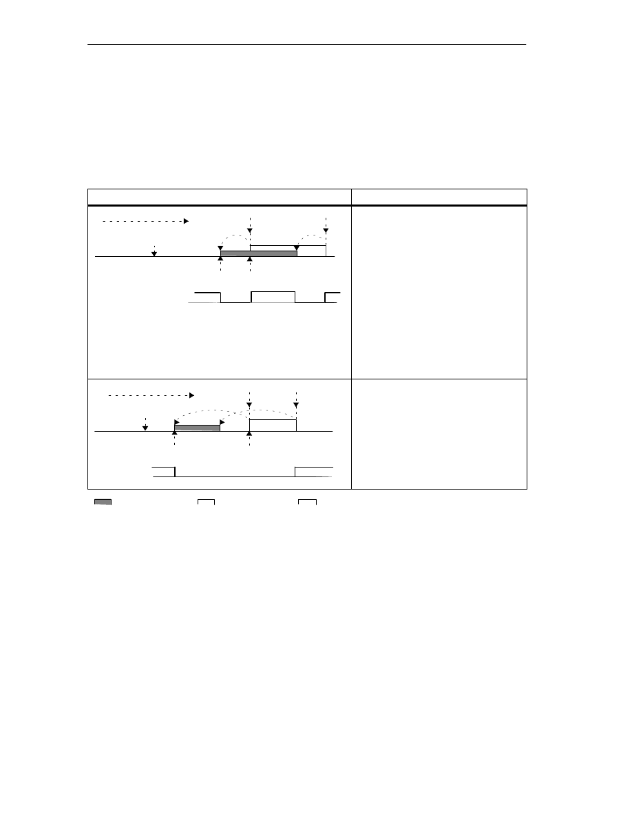
Machine Data and Cam Data
8-30
FM 352 Electronic Cam Controller
C79000-G7076-C352-04
Dynamic Adjustment on a Cam
There are two distinct situations relating to the range of the cam:
1. The static and dynamic range of the cam overlap.
2. The static and dynamic range of the cam do not overlap.
Table 8-1
Dynamic Adjustment on a Cam (Different Cases)
Dynamic Adjustment
Description
Cam n
Lead distance
CE
CS
Actual value
Dynamic Adjustment
Direction of travel
ÇÇÇÇ
ÇÇ
ÇÇ
If the dynamic range of the cam overlaps
the static range of the cam, the following
applies:
•
If the dynamic range of the cam has
been reached, the cam is activated.
At the same time, calculation of a
new dynamic adjustment is disabled.
•
If the actual value reaches the static
range of the cam, the calculation of a
new dynamic adjustment is enabled
again, a change in feedrate affects
the cam end.
•
If the cam is deactivated at the end
of the dynamic range, dynamic
adjustment is disabled again until the
end of the static range of the cam.
Cam n
Lead distance
CE
CS
Actual value
Dynamic
adjustment
Direction of travel
ÇÇÇ
ÇÇÇ
ÇÇ
ÇÇ
If the dynamic range of the cam does
not overlap the static range of the cam,
the following applies:
•
If the dynamic range of the cam has
been reached, the cam is activated.
At the same time, calculation of a
new dynamic adjustment is disabled.
•
At the end of the static range of the
cam, dynamic adjustment is enabled
again.
Static range
Dynamic range
ÇÇ
ÇÇ
A new dynamic adjustment is possible

9-1
FM 352 Electronic Cam Controller
C79000-G7076-C352-04
Settings
Chapter Overview
Section
Contents
Page
9.1
Influence of Settings on the Switching Response of Time Cams
9.2
Set Actual Value / Set Actual Value on-the-Fly / Cancel Set
Actual Value
9.3
Zero Offset
9.4
Set reference point
9.5
Changing Cam Edges
9.6
Fast Cam Parameter Change
9.7
Length Measurement / Edge Acquisition
9.8
Retrigger Reference Point
9.9
Deactivating the Software Limit Switches
9.10
Simulation
9.11
Counter Values of the Counter Cam Tracks
9.12
Position and Track Data
9.13
Encoder Data
9.14
Cam and Track Data
9.15
Control Signals for the Cam Controller
9.16
Return Signals for the Cam Controller
9.17
Return Signals for Diagnostics
9

Settings
9-2
FM 352 Electronic Cam Controller
C79000-G7076-C352-04
9.1
Influence of Settings on the Switching Response of Time Cams
Actual Value Changes
A time cam can be skipped by the following settings that change the actual value:
•
Set actual value
•
Set actual value on-the-fly
•
Zero Offset
•
Retrigger Reference Point
Switching a Time Cam
If you skip the start of a time cam due to one of the settings listed above, this cam
is activated as long as the actual direction in which the axis is moving matches the
activation direction set for the cam. The set on time runs until it expires.
Note
If the axis is stationary, the direction of movement depends on fluctuations in the
actual value.
If you want the direction of movement to be taken into account when the axis is
stationary, you must set a hysteresis that is greater than the fluctuations in the
actual value when the axis is stationary.
If the axis is not moving, the last detected direction of movement is retained.
!
Warning
Injury to persons or damage to equipment can occur.
With a rotary axis, settings that modify the actual value can led to accidental
activation of time cams.
You should always set the time cams of a rotary axis to “invalid” if you want to
modify the actual value using the settings listed above.

Settings
9-3
FM 352 Electronic Cam Controller
C79000-G7076-C352-04
9.2
Set Actual Value / Set Actual Value on-the-fly / Cancel Set
Actual Value
Definition
With the settings “Set actual value/Set actual value on-the-fly”, you assign a new
coordinate to the current encoder reading. The coordinate system is shifted as a
result by the value: ACT
new
- ACT
current
•
ACT
new
is the specified value
•
ACT
current
is the actual value at the time of execution.
Calculating the New Coordinates
All the positions you specify in the modified coordinate system can be calculated
according to the following formula:
coordinate
new
= coordinate
old
+ (ACT
new
- ACT
current
)
Requirements
•
The axis must be synchronized.
•
With “set actual value on-the-fly”: Digital input I1 must be connected.
Sequence of the Setting
1. Enter the coordinate for the actual value or for the flying actual value in the
channel DB.
– Linear axis:
You must select an actual value so that the software limit switch is still within
the range of movement after the setting has been read.
The value of the offset resulting from (ACT
new
- ACT
current
) must be less
than or equal to the value of the permitted travel range (maximum 100 m or
1000 m).
– Rotary axis
The following rule must apply to the specified actual value:
0
≤
actual value < end of rotary axis
2. Set the appropriate trigger bits in the channel DB.
3. Call FC CAM_CTRL.
“Set actual values” is executed immediately.
“Set actual value on-the-fly” is executed at the next rising edge at digital input
I1. The FVAL_DONE bit is set.

Settings
9-4
FM 352 Electronic Cam Controller
C79000-G7076-C352-04
Data Used in the Channel DB
Address
Name
Type
Initial Value
Comment
36.4
AVAL_EN
BOOL
FALSE
1 = Set actual value
36.5
FVAL_EN
BOOL
FALSE
1 = Set actual value on-the-fly
90.0
AVAL
DINT
L#0
Coordinate for actual value
94.0
FVAL
DINT
L#0
Coordinate for flying actual value
25.5
FVAL_DONE
BOOL
FALSE
1 = set actual value on-the-fly executed
Effects of the Setting
Based on the example “set actual value” to 400 mm (at position 200 mm), you can
see how this setting shifts the coordinate system. The following effects result:
•
The location of the working range is not physically shifted.
•
The individual points (such as the software limit switches) are assigned new
coordinate values.
•
The cams retain their coordinate values and are therefore located at a different
physical position.
•
When the axis is synchronized and the cam processing is enabled, the actual
position can skip cam edges or complete cams as a result of this setting.
•
Status changes of the cam which would normally trigger an interrupt can be
lost.
Note
Note the switching response of time cams in Section 9.1, page 9-2.
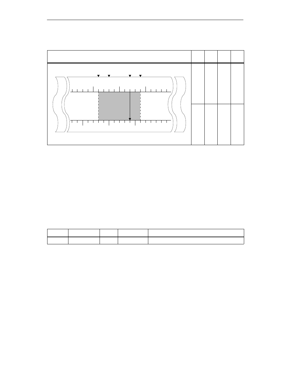
Settings
9-5
FM 352 Electronic Cam Controller
C79000-G7076-C352-04
Table 9-1
Displacement of the Coordinate System by “Set Actual Value” / “Set Actual Value on-the-Fly”
Set Actual Value
SLS
[mm]
REF
[mm]
ACT
[mm]
SLE
[mm]
SLS
ACT SLE
0
500
-500
REF
range
200
[mm]
Displacement
of coordi.
t
b
Old coordinate system
-400
-200
200
400
Axis
0
W
orking r
a
400
-500
system by
+200 mm: Set
actual value to
400 mm
[mm]
New coordinate system
-200
0
400
600
Canceling the Setting
With the setting ”Cancel set actual value”, you reset the coordinate displacement
that resulted from “set actual value” or “set actual value on-the-fly”.
Once “set actual value on-the-fly” has been triggered, it can no longer be deleted
before execution by a rising edge at input I1. However, it can be overwritten by a
new “set actual value on-the-fly”.
During a module start up, these settings are reset.
Data Used in the Channel DB
Address
Name
Type
Initial Value
Comment
35.2
AVALREM_EN
BOOL
FALSE
1: Cancel actual value setting
Possible Sources of Error
“Set actual value on-the-fly” and “Retrigger reference point” must not be executed
at the same time.
With the setting “set actual value on-the-fly”, an error can be signaled if the setting
means that a software limit switch would be exceeded with the rising edge at I1.
This operating error is signaled by a diagnostic interrupt and entered in the
diagnostic buffer.

Settings
9-6
FM 352 Electronic Cam Controller
C79000-G7076-C352-04
9.3
Zero Offset
Definition
With the “zero offset” setting, you shift the zero point in the coordinate system by
the specified value. The sign determines the direction of the shift.
Calculating the New Coordinate
All the values in the shifted coordinate system can be calculated according to the
following formula:
coordinate
new
= coordinate
old
- (ZPO
new
- ZPO
old
)
ZPO
old
is any existing old zero point offset. If no zero offset was active before the
call, set the value 0 for ZPO
old
.
With this formula, you can calculate which coordinate values are adopted, for
example,by the software limit switches.
Sequence of the Setting
1. Enter the value for the zero offset in the channel DB.
– Linear axis:
The zero offset must be selected so that the software limit switch is still
within the permissible range after the setting is read.
– Rotary axis
The following rule must apply to the zero offset:
amount of zero offset
≤
end of the rotary axis.
2. Set the appropriate trigger bit.
Data Used in the Channel DB
Address
Name
Type
Initial Value
Comment
36.6
ZOFF_EN
BOOL
FALSE
1 = set zero offset
86.0
ZOFF
DINT
L#0
Zero Offset
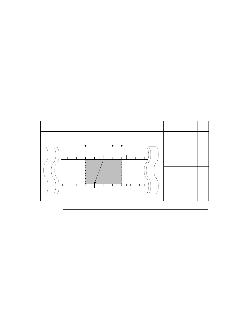
Settings
9-7
FM 352 Electronic Cam Controller
C79000-G7076-C352-04
Effects on a Linear Axis
Based on the example of a zero offset of -200 mm you can see that this setting
shifts the coordinate system in a positive direction. The following effects result:
•
The working range is not physically shifted.
•
The individual points (such as the software limit switches) are assigned new
coordinate values.
•
The cams retain their coordinate values and are therefore located at a different
physical position.
•
When the axis is synchronized and the cam processing is enabled, the actual
position can skip cam edges or complete cams as a result of this setting.
•
Status changes of the cam which would normally trigger an interrupt can be
lost.
Table 9-2
Coordinate System Shift Resulting from Zero Offset
Zero Offset
SLS
[mm]
REF
[mm]
ACT
[mm]
SLE
[mm]
SLS
ACT SLE
Axis
0
500
-500
n
ge
200
[mm]
Coordinate
hift f
Old coordinate system
-400
-200
200
400
0
W
orking ran
g
400
-500
shift of
200 mm
resulting from
zero offset of
-200 mm
[mm]
New coordinate system
-200
0
400
600
Note
Note the switching response of time cams in Section 9.1, page 9-2.
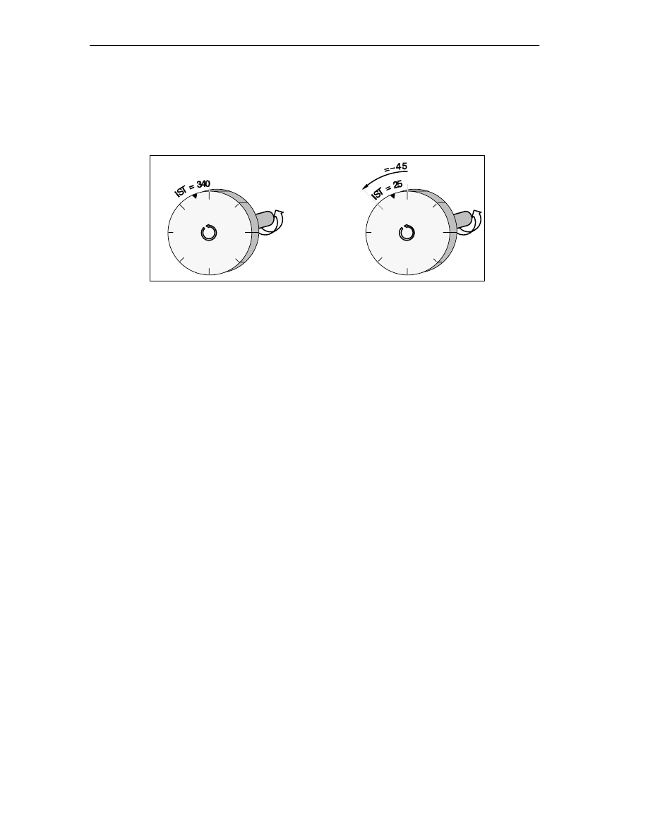
Settings
9-8
FM 352 Electronic Cam Controller
C79000-G7076-C352-04
Effects on a Rotary Axis
Based on the example of a zero offset by -45
°
, you can see how this setting turns
the coordinate system:
0
180
0
180
Tool at ACT = 340
The zero point
turns through
-45 degrees. All
points on the
axis receive
new coordinate
values
Tool at ACT =
25
ZPO
Figure 9-1
Rotation of the Coordinate System Resulting from a Zero Offset
Taking into account a ZPO
old
= 0 a new value of 385
°
results.
The actual value beings again at 0 at the end of the rotary axis when this is turning
in a positive direction so that the value actually calculated is 25
°
:
coordinate
new
= coordinate
old
- (ZPO
new
- ZPO
old
) -end of rotary axis
The value end of rotary axis only needs to be subtracted when
coordinate
old
- (ZPO
new
- ZPO
old
) will be higher than the end of the rotary axis.
Loss of Synchronization
If synchronization is lost due to an error or is reset due to “retrigger reference
point”, a zero offset is retained.
Canceling the Setting
By setting a zero offset of 0, you reset an existing offset.

Settings
9-9
FM 352 Electronic Cam Controller
C79000-G7076-C352-04
9.4
Set Reference Point
Definition
With the “set reference point” setting, you synchronize the axis. The setting shifts
the working area. All shifts resulting from a zero offset or from “set actual value”
remain in force.
Requirements
Cam processing must be switched off.
Sequence of the Setting
1. Enter the value for the reference point coordinate in the channel DB.
– Linear axis:
The reference-point coordinate must not be located outside the software
limit switches. This also applies to the reference point coordinate in a shifted
coordinate system.
– Rotary axis
The following rule applies to the reference point coordinate:
0
≤
reference point coordinate
<
end of rotary axis
2. Set the appropriate trigger bit.
Date Used in the Channel DB
Address
Name
Type
Initial Value
Comment
36.3
REFPT_EN
BOOL
FALSE
1 = set reference point coordinate
98.0
REFPT
DINT
L#0
Reference point coordinate
25.0
SYNC
BOOL
FALSE
1 = axis synchronized
Effects of the Setting
Based on the example “set reference point” to 300 mm, you can see how this
setting shifts the working range of the axis.
This has the following effects:
•
The actual position is set to the value of the reference-point coordinate.
•
The working range is physically shifted on the axis.
•
The individual points retain their original coordinates but are located at new
physical locations.
•
The SYNC bit is set in the return signals.
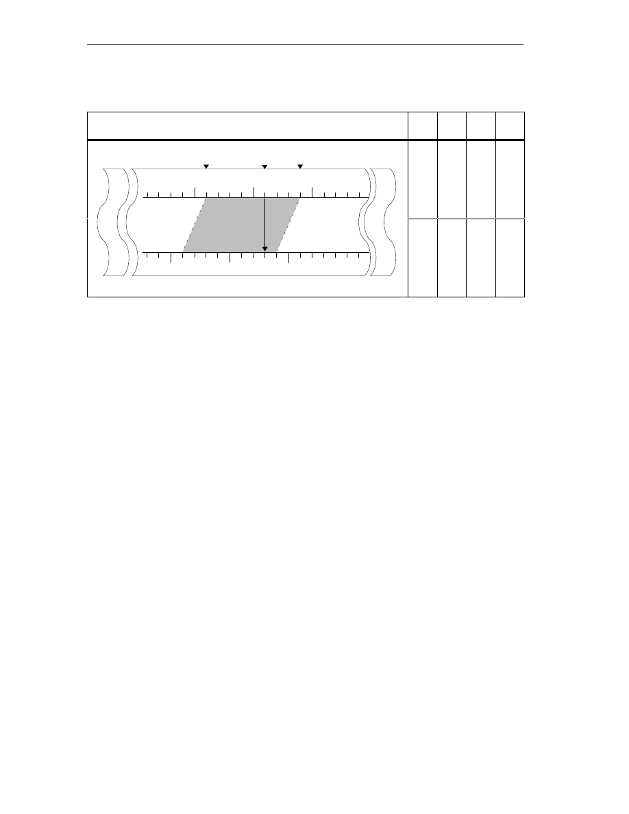
Settings
9-10
FM 352 Electronic Cam Controller
C79000-G7076-C352-04
Table 9-3
Shifting the Working Range on the Axis Using “Set Reference Point””
Set reference point
SLS
[mm]
REF
[mm]
ACT
[mm]
SLE
[mm]
Shift in the
working range
SLS
ACT
SLE
Axis
0
500
-500
100
[mm]
Old coordinate system
R
ang
e
-400
-200
100
400
working range
to 300 mm with
“set reference
point”
0
300
-500
[mm]
New coordinate system
Working R
a
-400
-200
300
400
Note on Absolute Encoders
This setting is necessary for an absolute encoder adjustment (see section 8.4,
page 8-12).

Settings
9-11
FM 352 Electronic Cam Controller
C79000-G7076-C352-04
9.5
Changing the Cam Edges
Definition
With the “change cam edges” setting, you can change the cam start and, with
distance cams, also the cam end of a single cam.
Requirements
The cam you want to change must be valid.
Sequence of the Setting
1. Enter the cam number in the channel DB.
2. For a distance cam:
Enter the cam start and cam end in the channel DB.
With a time cam:
Enter the value for the cam start in the channel DB.
3. Set the appropriate trigger bit.
Data Used in the Channel DB
Address
Name
Type
Initial Value
Comment
36.7
CH01CAM_EN
BOOL
FALSE
1 = write setting for cam edges (one cam)
102.0
CAM_NO
INT
0
Cam number
104.0
CAM_START
DINT
L#0
Cam start
108.0
CAM_END
DINT
L#0
Cam end
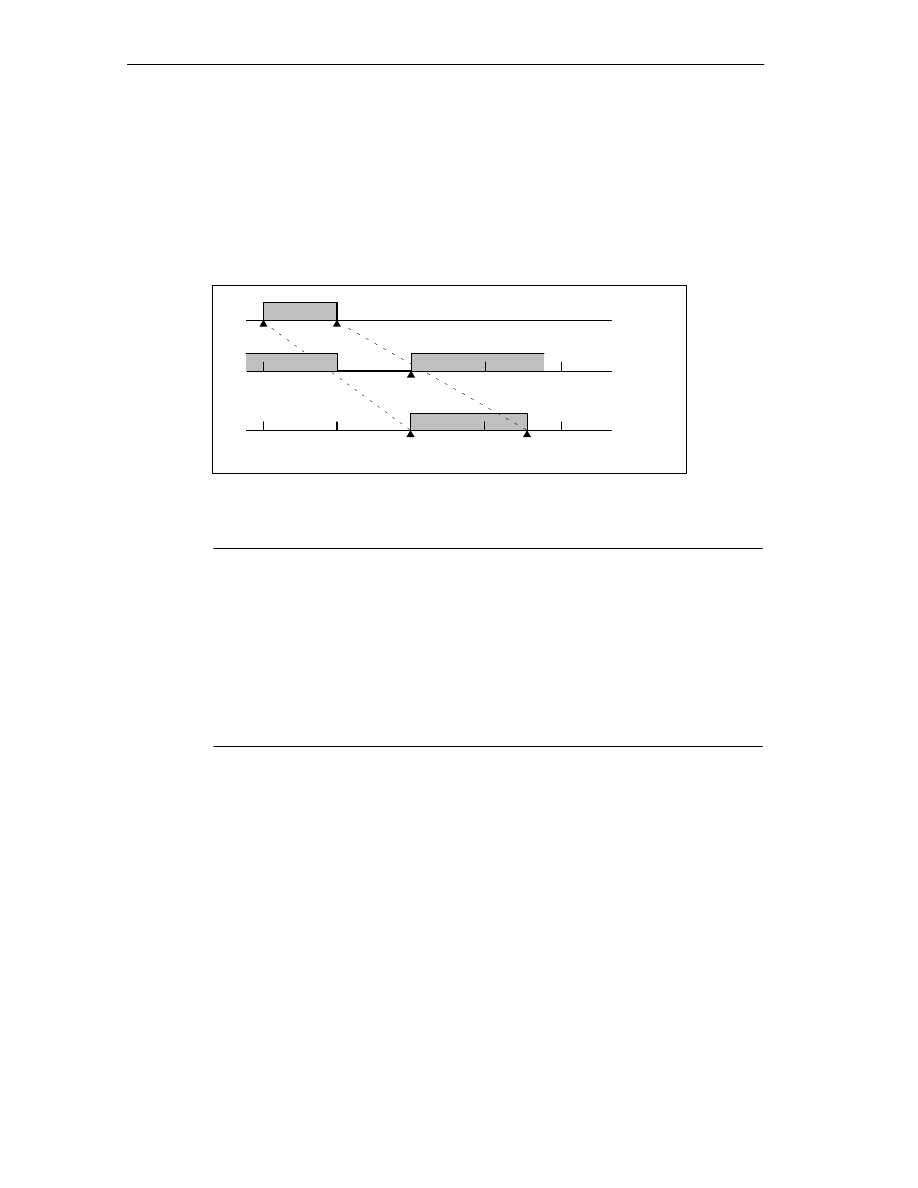
Settings
9-12
FM 352 Electronic Cam Controller
C79000-G7076-C352-04
Effects of the Setting
The FM 352 first shifts the on edge and then the off edge of the cam. This
sequence does not depend on the direction in which the cam is shifted.
Special situation:
Due to the sequence explained above, an inverse cam can result briefly if the new
cam start is higher than the old cam end.
CS
CE
CS
CE
150 mm
160 mm
=185 mm
150 mm
160 mm
=CE
old
CS
new
Before
calling
During the
call
After the
call
Figure 9-2
Changes in the Cam Edges in Individual Steps
Note
If a hardware interrupt has been enabled for this cam, the FM 352 can trigger one
or two hardware interrupts depending on parameter settings, when the inverse
cam is detected.
Changing the on and/or off edge can result in a cam edge or the entire cam being
skipped.
Note the switching response of time cams in Section 9.1, page 9-2.
Cam status changes that would normally trigger a hardware interrupt can be lost.
Reading Out Modified Values
You can read out modified values with one of the jobs CAM1RD_EN to
CAM8RD_EN.
Canceling the Setting
The modified values are lost when you restart the module.

Settings
9-13
FM 352 Electronic Cam Controller
C79000-G7076-C352-04
9.6
Fast Cam Parameter Change
Definition
With the “fast cam parameter change” setting, you can modify up to 16 cams at the
same time during operation.
Requirements
The cams you want to modify must be valid.
Sequence of the Setting
1. Enter the number of cams to be modified in the channel DB.
2. Enter the number of the first cam to be modified in the channel DB.
3. Set the trigger bits for the required modifications.
4. Enter the new values in the channel DB.
5. Repeat steps 2 - 4 for each cam to be modified.
6. Set the appropriate trigger bit in the channel DB.
Data Used in the Channel DB
Address
(abs)
Name
Type
Initial Value
Comment
37.0
CH16CAM_EN
BOOL
FALSE
1 = settings for fast cam parameter change
(16 cams)
176.0
C_QTY
BYTE
B#16#0
Number of cams to be modified
177.0
DIS_CHECK
BOOL
FALSE
1 =deactivate data check
Address
(rel)
Name
Type
Initial Value
Comment
+0.0
CAM_NO
BYTE
B#16#0
Number of the cam to be modified
+1.0
C_EFFDIR
BOOL
FALSE
1 = change the cam activation direction
+1.1
C_CBEGIN
BOOL
FALSE
1 = change the cam start to the value CBEGIN
+1.2
C_CEND
BOOL
FALSE
1 = change the cam end / on time to the value
CEND
+1.3
C_LTIME
BOOL
FALSE
1 = change the lead time to the value LTIME
+1.4
CAM_OFF
BOOL
FALSE
1 = deactivate the cam during the cam
modification
+1.5
EFFDIR_P
BOOL
FALSE
1 = activation direction positive (plus)
+1.6
EFFDIR_M
BOOL
FALSE
1 = activation direction negative (minus)
+2.0
CBEGIN
DINT
L#0
New cam start
+6.0
CEND
DINT
L#0
New cam end / new on time
+10.0
LTIME
INT
0
New lead time

Settings
9-14
FM 352 Electronic Cam Controller
C79000-G7076-C352-04
Deactivating a Cam During Modification
A consistent modification of the cam start and the cam end is only possible if you
deactivate the cam during the modification (CAM_OFF).
Data Check by the Module
With the DIS_CHECK (channel DB) parameter, you activate or deactivate the
checking of the transferred data by the FM 352. If you disable the data check, you
yourself must make sure that only permitted values are transferred. If you transfer
illegal values without a check, the module may react unexpectedly.
•
FALSE: The module checks all data to be transferred
•
TRUE: The data check for the cam parameters is deactivated. This means that
the data to be changed can be processed faster on the FM 352.
Regardless of this setting, a check is always made to determine the following:
– Has the axis had parameters assigned?
– Is the number of cams to be modified (C_QTY) permitted?
– Is the cam (cam number) to be modified valid?
Only when all data have been checked and are error-free are they activated on the
module.
In the event of an error, all data are rejected.
Effects of the Setting
Note
Note the switching response of time cams in Section 9.1, page 9-2.
Reading Out Modified Values
You can read out the modified values with one of the jobs CAM1RD_EN to
CAM8RD_EN .
Canceling the Setting
The modified values are lost when you restart the module.

Settings
9-15
FM 352 Electronic Cam Controller
C79000-G7076-C352-04
9.7
Length Measurement/Edge Acquisition
Definition
With the settings “length measurement” and “edge detection”, you can find out the
length of a workpiece.
The length measurement and edge detection are and remain active until you
deactivate them again or until you select a different measuring method. If you
select both methods at the same time, FC CAM_CTRL activates the length
measurement.
Requirements
A bounce-free switch must be connected at input I1.
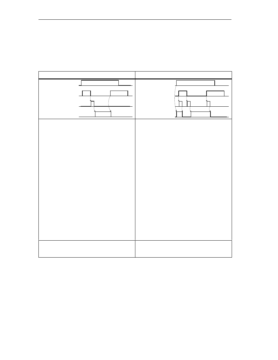
Settings
9-16
FM 352 Electronic Cam Controller
C79000-G7076-C352-04
Sequence of the Settings
Depending on the type of measurement, the FM 352 updates the data on the
module at different times. The FM 352 signals every update in a parameter on the
return interface.
Length Measurement
Edge Detection
MSR_ON
I1
Update data
MSR_DONE
EDGE_ON
I1
Update data
MSR_DONE
1. Set the function switch for “length
measurement”.
2. The rising edge of input I1 starts the length
measurement.
3. The falling edge of input I1 terminates a
measurement in progress. The FM 352 updates
the data start value, end value, and length.
4. With the MSR_DONE parameter set, the
FM 352 signals the updating of the data. The
parameter indicates that the measurement is
completed. The results of the measurement can
be read out.
5. The start of another measurement with the
rising edge of I1 resets the MSR_DONE
parameter.
1. If necessary, enter a value for the minimum
edge-to-edge distance in the parameter DB.
Write and activate the machine data.
2. Set the function switch for “edge detection”. The
MSR_DONE parameter is set.
3. The rising edge of input I1 starts the edge
acquisition. The results of the measurement are
updated and can be read out, the start of the
measurement is entered; the end value and
length become -1.
4. After the update, the FM 352 signals the
change by resetting the MSR_DONE
parameter.
5. The falling edge of input I1 terminates a
measurement in progress. The FM 352 updates
the data for end value of the measurement and
length.
6. After the update, the FM 352 signals the
change by setting the MSR_DONE parameter.
The results of the measurement can be read
out.
7. The start of another measurement with the
rising edge of I1 resets the MSR_DONE
parameter.
If the setting is switched off during a length
measurement, the FM 352 does not update the
data. The MSR_DONE parameter remains reset.
If the setting is switched off during edge acquisition,
the FM 352 does not update the data. The
MSR_DONE parameter remains reset.

Settings
9-17
FM 352 Electronic Cam Controller
C79000-G7076-C352-04
Data Used in the Channel DB
Address
Name
Type
Initial Value
Comment
25.1
MSR_DONE
BOOL
FALSE
1 = length measurement completed
34.0
EDGE_ON
BOOL
FALSE
1 = edge detection on
34.2
MSR_ON
BOOL
FALSE
1 = length measurement on
38.2
MSRRD_EN
BOOL
FALSE
1 = read measured values
112.0
BEG_VAL
DINT
L#0
Start value
116.0
END_VAL
DINT
L#0
End value
120.0
LEN_VAL
DINT
L#0
Length
Data Used in the Parameter DB
Address
Name
Type
Initial Value
Comment
4.0
EDGEDIST
DINT
L#0
Minimum edge-to-edge distance for edge
detection
Range:
0 ... 1 000 000 000
m
With the minimum edge-to-edge distance, you define a range after detection of the start of measurement
when using edge acquisition. If the end of the measurement is within this range, the measurement is
rejected.
The start of the measurement is signaled only after the minimum edge-to-edge distance has been
traveled.
Conditions for Length Measurement
•
The distance between the off edge and on edge at input I1 must be large
enough so that your program on the CPU can evaluate the measurement result
correctly before a new measurement begins.
•
The minimum interval between the rising and the falling edge at input I1 as well
as between the falling and the next rising edge at input I1 must be greater than
2 ms.

Settings
9-18
FM 352 Electronic Cam Controller
C79000-G7076-C352-04
Incorrect Measurement
If a length measurement / edge detection is incorrect, the FM 352 returns the value
-1 for the length.
A “length measurement” or “edge detection” can pass through zero a maximum of
126 times
1
in one direction. As soon as more than 126 zero passes in one
direction are recognized by the FM 352, an incorrect “length measurement” or
“edge detection” is signaled even when zero passes in the other direction were
detected afterwards.
A length measurement error also occurs when:
•
The measured length of a rotary axis is greater than 2
31
.
•
The on and off edges are detected simultaneously by the FM 352 (for example,
caused by switch bounce).
Adjustment of the Coordinate System During Length Measurements
Adjustments in the coordinate system influence the measured length in the
following situations:
•
You are using an incremental encoder or an initiator and you are operating the
FM 352 in the simulation mode.
•
You are running “set reference point” or “retrigger reference point” during an
active length measurement.
Example
You can use the influences on the measured length listed above as follows:
You have, for example, a system in which a slip always occurs during length
measurement.
With retrigger reference point, you can correct this slip so that correct length
measurement values are then output.
1
Zero pass = rotary axis pass from the “end of rotary axis” value to 0 and vice versa

Settings
9-19
FM 352 Electronic Cam Controller
C79000-G7076-C352-04
9.8
Retrigger Reference Point
Definition
With the “retrigger reference point” setting, you can synchronize the axis in
response to a recurrent external event.
The setting remains active until you switch it off again.
Requirements
•
You are using an incremental encoder or initiator.
•
The external event can be a zero marker of an incremental encoder or a
reference point switch at input I2.
Sequence of a Setting
1. Enter the value for the reference point coordinate in the parameter DB.
2. Enter the type of “retrigger reference point” in the parameter DB.
Here, you have the following options:
•
Only the zero marker of the encoder is evaluated (RETR_TYPE = 7).
•
Only the reference point switch is evaluated (RETR_TYPE = 6).
•
The zero marker is evaluated
– in the positive direction: the first rising edge of the zero marker after
leaving the reference point switch in a positive direction is evaluated
(RETR_TYPE = 0).
– in negative direction: the first falling edge of the zero marker after leaving
the reference point switch in a negative direction is evaluated
(RETR_TYPE = 1).
3. Write and activate the machine data.
4. Set the function switch in the channel DB.

Settings
9-20
FM 352 Electronic Cam Controller
C79000-G7076-C352-04
Data Used in the Channel DB
Address
Name
Type
Initial Value
Comment
34.3
REFTR_ON
BOOL
FALSE
1 = retrigger reference point
25.0
SYNC
BOOL
FALSE
1 = axis is synchronized
Data Used in the Parameter DB
Address
Name
Type
Initial Value
Comment
44.0
REFPT
DINT
L#0
Reference point coordinate
52.0
RETR_TYPE
DINT
L#0
Type of retrigger reference point
Effects of the Setting
•
The FM 352 evaluates the zero marker and the reference point switch
depending on the direction of movement of the axis.
– If movement is in a positive direction, the rising edges are evaluated.
– If movement is in a negative direction, the falling edges are evaluated.
•
The actual position is set to the value of the reference point coordinate.
•
The working range is physically shifted on the axis.
•
The individual points retain their original value, but are now located at new
physical positions.
•
Cam status changes that would normally trigger an interrupt can be lost.
•
The SYNC bit is set in the return signals.
Note
Note the switching response of time cams in Section 9.1, page 9-2.
Example
The following applies to the example:
•
The rising edges of the reference point switch and zero marker are evaluated
(axis moving in a positive direction).
•
The reference point coordinate has a value 300 mm.
•
No zero offset is active at the time of execution.
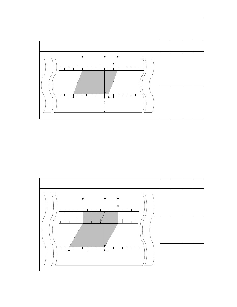
Settings
9-21
FM 352 Electronic Cam Controller
C79000-G7076-C352-04
Table 9-4
Displacement of the Working Range on the Axis by Retrigger Reference Point
Retrigger reference point
SLS
[mm]
REF
[mm]
ACT
[mm]
SLE
[mm]
Displacement
of the working
range by
retrigger
SLS
ACT
SLE
Axis
0
500
-500
REF
100
[mm]
Old coordinate system
ing Range
-400
300
100
400
retrigger
reference point at
300 mm
0
400
-500 SLS
ACT=REF
SLE
[mm]
New coordinate system
W
orki
n
-400
300
300
400
Including a Zero Offset
If a zero offset is active, this is taken into account in the retrigger reference point
setting. This means that the reference point coordinate set is calculated according
to the following formula:
Ref = Ref
MD
- zero offset
Ref
MD
is the value stored as the reference point coordinate in the machine data.
Table 9-5
Displacement of the Working Range on the Axis by Retrigger Reference Point with Zero Offset
Retrigger Reference Point
SLS
[mm]
REF
[mm]
ACT
[mm]
SLE
[mm]
Axis
SLS
ACT
SLE
0
500
-500
REF
ZPO=-100
0
Old coordinate system
[mm]
-500
300
0
300
Displacement
of the working
range by retrigger
reference point
ZPO=-100
0
W
orking Range
-400
400
100
400
reference point
0
500
-500
SLS
SLE = REF=REF
MD
-ZPO
[mm]
New coordinate system
W
o
-400
400
400
400

Settings
9-22
FM 352 Electronic Cam Controller
C79000-G7076-C352-04
9.9
Deactivating Software Limit Switches
Definition
With the “deactivate software limit switch” setting, you deactivate the monitoring of
the software limit switches of the linear axis.
The setting remains active until you switch it off again. The software limit switches
originally set then become active again.
Sequence of the Setting
Set the function switch in the channel DB.
Data Used in the Channel DB
Address
Name
Type
Initial Value
Comment
34.4
SSW_OFF
BOOL
FALSE
1 = software limit switch off
Data Used in the Parameter DB
Address
Name
Type
Initial Value
Comment
64.0
SSW_STRT
DINT
L#-1000000000
Start of software limit switch
68.0
SSW_END
DINT
L#1000000000
End of software limit switch
Effects of the Setting
•
Simulation
– If a software limit switch is passed in the simulation mode, the simulation
mode is stopped.
– If you then deactivate the monitoring of the software limit switches, the
simulation mode is resumed. The axis moves in the specified direction.
•
Zero offset when monitoring is switched off.
If a zero offset is specified in which the software limit switches are still within the
traverse range limits, the actual value can still be outside the permissible
number range.
•
Cams lying outside the set software limit switches can be activated.
!
Caution
Damage to equipment is possible.
If you restrict the travel range with the software limit switches as a safety
measure, deactivating the limit switches can result in serious damage to
equipment.
Please ensure when planning your plant and system that the drive can travel
within the entire physical range.

Settings
9-23
FM 352 Electronic Cam Controller
C79000-G7076-C352-04
9.10
Simulation
Definition
The “simulation” setting allows you to activate the cam controller without connected
encoders.
Sequence of the Setting
1. Enter the simulation speed in the parameter DB.
2. Write and activate the machine data.
3. Select either the positive or negative direction in the channel DB as the
simulation direction.
4. Set the function switch in the channel DB.
Data Used in the Channel DB
Address
Name
Type
Initial Value
Comment
15.2
DIR_M
BOOL
FALSE
1 = simulation in negative direction
15.3
DIR_P
BOOL
FALSE
1 = simulation in positive direction
34.1
SIM_ON
BOOL
FALSE
1 = simulation on
Data Used in the Parameter DB
Address
Name
Type
Initial Value
Comment
84.0
SIM_SPD
DINT
L#0
Simulation Speed
Effects of Activating Simulation
•
The encoder signals are no longer evaluated.
•
All monitoring relevant to the encoder input is deactivated.
•
Any errors signaled with reference to the encoder are reset.
•
The FM 352 simulates the movement of an axis at the constant simulation
speed.
•
Cam processing is switched off when simulation is switched on. However, you
can then switch it back on again. The synchronization is retained.
•
The actual position changes from the current actual value depending on the
simulation speed and the simulation direction.

Settings
9-24
FM 352 Electronic Cam Controller
C79000-G7076-C352-04
Effects of Deactivating Simulation
•
Cam processing is stopped
•
The synchronization is deleted for an incremental encoder or an initiator. The
value of the reference point coordinate is then set as the actual value.
•
With an absolute encoder, the actual position is signaled that corresponds to
the current encoder status. The encoder signals are again evaluated according
to the parameter settings in the machine data.
Limit Values
The maximum and minimum limits of the simulation speed depend on the
resolution (see Section 8.3, page 8-7).
Feedrate
There may be a difference between the set and actual feedrate at which the
module works (see Section 8.3. page 8-7).

Settings
9-25
FM 352 Electronic Cam Controller
C79000-G7076-C352-04
9.11
Counted Values of the Counter Cam Tracks
Definition
With the “counted values of the counter cam tracks” setting, you read out the
current counted values.
Sequence of the Setting
1. Specify the counter cam tracks and the upper counted values in the machine
data.
2. Write and activate the machine data.
3. Enable the counter function.
4. The counted value is set to the upper counted value.
5. At each rising edge of the track result, the counted value is decremented by 1.
6. Set the trigger bit in the channel DB to read the counted values.
7. The counted values for both tracks are written to the channel DB. If the track is
not set as a counter cam track, 0 is output.
8. If the counted value reaches the value 0, the track flag bit of the counter cam
track is set to 1.
9. With the next falling edge at the track result, the track flag bit is set back to 0
and the counter is set to the upper counted value.
Data Used in the Channel DB
Address
Name
Type
Initial Value
Comment
15.5
CNTC0_EN
BOOL
FALSE
1 = enable count function of counter cam track 0
15.6
CNTC1_EN
BOOL
FALSE
1 = enable count function of counter cam track 1
38.3
CNTTRC_EN
BOOL
FALSE
1 = read count values of counter cam tracks
124.0
CNT_TRC0
INT
0
Current counter value for counter cam track 0
126.0
CNT_TRC1
INT
0
Current counter value for counter cam track 1
Data Used in the Parameter DB
Address
Name
Type
Initial Value
Comment
99.0
SPEC_TRC0
BOOL
FALSE
1 = track 0 is counter cam track
99.1
SPEC_TRC1
BOOL
FALSE
1 = track 1 is counter cam track
100.0
CNT_LIM0
DINT
L#2
Upper counter value for counter cam track 0
104.0
CNT_LIM1
DINT
L#2
Upper counter value for counter cam track 1

Settings
9-26
FM 352 Electronic Cam Controller
C79000-G7076-C352-04
9.12
Position and Track Data
Definition
With the setting “position and track data”, you read the current actual position, the
feedrate and the track flag bits. The track flag bits are acquired before they are
logically combined with machine and channel data.
The calculation algorithm implemented on the FM 352 calculates speed changes
greater than 1 pulse per 4 ms with a slight inaccuracy. The displayed speed
therefore includes this inaccuracy and is unsuited, in particular, for closed-loop
control. The internal speed used the dynamic values of the cam is more accurate.
Sequence of the Setting
1. Set the trigger bit in the channel DB.
2. The data are stored in the channel DB.
Data Used in the Channel DB
Address
Name
Type
Initial Value
Comment
38.4
ACTPOS_EN
BOOL
FALSE
1 = read position and track data
128.0
ACTPOS
DINT
L#0
Current position
132.0
ACTSPD
DINT
L#0
Current feedrate
136.0
TRACK_ID
DWORD
DW#16#0
Track flag bits of tracks 0 to 31

Settings
9-27
FM 352 Electronic Cam Controller
C79000-G7076-C352-04
9.13
Encoder Data
Definition
With the “encoder data” setting, you read the current data of the encoder and the
value of the absolute encoder adjustment.
Requirements
You can read out the value for the absolute encoder adjustment after making the
setting “set reference point” (see Section 8.4, page 8-12).
Sequence of the Setting
1. Set the trigger bit in the channel DB.
2. The data are stored in the channel DB.
Data Used in the Channel DB
Address
Name
Type
Initial Value
Comment
38.5
ENCVAL_EN
BOOL
FALSE
1 = read encoder values
140.0
ENCVAL
DINT
L#0
Encoder value / counter value (internal
representation)
144.0
ZEROVAL
DINT
L#0
Counter value at the last zero marker (internal
representation)
148.0
ENC_ADJ
DINT
L#0
Absolute encoder adjustment

Settings
9-28
FM 352 Electronic Cam Controller
C79000-G7076-C352-04
9.14
Cam and Track Data
Definition
With the setting “cam and track data”, you read the current cam and track flag bits
and the position. The track flag bits are acquired before they are logically
combined with machine and channel data.
Sequence of the Setting
1. Enter a 1 in the FM_TYPE parameter of the channel DB as the type identifier.
This allows you to read 24 bytes of cam and track data.
If you enter 0 as the type identifier, only the cam flag bits (16 bytes) are read.
2. The data are stored in the channel DB.
Data Used in the Channel DB
Address
Name
Type
Initial Value
Comment
12.0
FM_TYPE
BOOL
FALSE
0 = FM 352 up to V4.0
1 = FM 352 / FM 452 V5.0 or higher
38.6
CAMOUT_EN
BOOL
FALSE
1 = read cam and track data
152.0
CAM_00_31
DWORD
DW#16#0
Cam flag bits for cams 0 to 31
156.0
CAM_32_63
DWORD
DW#16#0
Cam flag bits for cams 32 to 63
160.0
CAM_64_95
DWORD
DW#16#0
Cam flag bits for cams 64 to 95
164.0
CAM_96_127
DWORD
DW#16#0
Cam flag bits for cams 96 to 127
168.0
TRACK_ID1
DWORD
DW#16#0
Track flag bits of tracks 0 to 31
172.0
ACTPOS1
DINT
L#0
Current position

Settings
9-29
FM 352 Electronic Cam Controller
C79000-G7076-C352-04
9.15
Control Signals for the Cam Controller
Definition
With the “control signals for the cam controller” setting, you enable cam processing
and the tracks.
Sequence of the Setting
1. Set the trigger bit in the channel DB.
2. The data are transferred to the module whenever FC CAM_CTRL is called.
Data Used in the Channel DB
Address
Name
Type
Initial Value
Comment
15.4
CAM_EN
BOOL
FALSE
1 = enable cam processing
16.0
TRACK_EN
WORD
W#16#0
Enable cam tracks 0 to 12
Bit 0 = track 0
Effects
The cam processing is started or stopped depending on the enable.
The track flag bits of the enabled tracks are passed on to the track signals and the
digital outputs.

Settings
9-30
FM 352 Electronic Cam Controller
C79000-G7076-C352-04
9.16
Return Signals for the Cam Controller
Definition
The “return signals for the cam controller” setting informs you about the current
state of the cam controller and the track signals. Consistency between the signaled
position and the track signals is not guaranteed.
Sequence of the Setting
1. Set the trigger bit in the channel DB.
2. The data are stored in the channel DB whenever FC CAM_CTRL is called.
Data Used in the Channel DB
Address
Name
Type
Initial Value
Comment
23.4
CAM_ACT
BOOL
FALSE
1 = cam processing active
26.0
ACT_POS
DINT
L#0
Current position of the axis
30.0
TRACK_OUT
DWORD
DW#16#0
Current track signals tracks 0 to 31
Bit 0 = track 0

Settings
9-31
FM 352 Electronic Cam Controller
C79000-G7076-C352-04
9.17
Return Signals for Diagnostics
Definition
The “return signals for diagnostics” setting informs you of diagnostic events that
have occurred.
Sequence of the Setting
1. When the module makes a new entry in the diagnostic buffer, it sets the DIAG
bit. Whenever an error occurs belonging to any of the error classes listed in
Appendix C, an entry is made in the diagnostic buffer.
2. If the module recognizes a write job with incorrect data, it sets the DATA_ERR
bit. The cause of the error is entered in the diagnostic buffer.
3. The data are stored in the channel DB.
4. If the diagnostic buffer is read by FC DIAG or by the error evaluation of the
parameter assignment user interface, the module sets the DIAG bit back to 0.
Data Used in the Channel DB
Address
Name
Type
Initial Value
Comment
22.2
DIAG
BOOL
FALSE
1 = diagnostic buffer modified
22.4
DATA_ERR
BOOL
FALSE
1 = data error

Settings
9-32
FM 352 Electronic Cam Controller
C79000-G7076-C352-04

10-1
FM 352 Electronic Cam Controller
C79000-G7076-C352-04
Encoders
Chapter Overview
Section
Contents
Page
10.1
Incremental Encoders
10.2
Initiators
10.3
Absolute Encoders
10
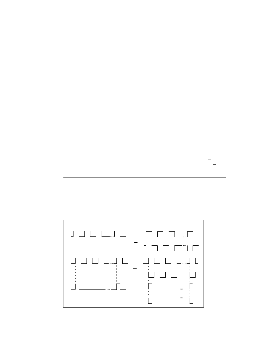
Encoders
10-2
FM 352 Electronic Cam Controller
C79000-G7076-C352-04
10.1
Incremental Encoders
Connectable Incremental Encoders
Incremental encoders with two pulses electrically offset by 90
°
with or without zero
markers are supported:
•
Encoders with asymmetrical output signals with 24 V level
– Cut-off frequency = 50 kHz:
– max. 100 m line length.
•
Encoders with symmetrical output signals with 5 V differential interfaces
conforming to RS-422
– Cut-off frequency = 1 MHz
– At 5 V supply voltage: max. 32 m line length.
– At 24 V supply voltage: max. 100 m line length.
Note
If the encoder (5 V) does not output a zero marker signal and you have activated
the wire-break monitoring, you must switch the zero marker inputs N and N
externally so that these inputs have a different level (for example, N on 5 V, N on
ground).
Signal Shapes
Figure 10-1 illustrates the signal shapes from encoders with asymmetrical and and
symmetrical output signals.
asymmetrical
symmetrical
A*
B*
N*
A
B
N
A
B
N
Figure 10-1
Signal Shapes from Incremental Encoders
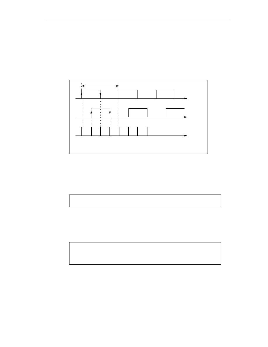
Encoders
10-3
FM 352 Electronic Cam Controller
C79000-G7076-C352-04
Signal evaluation
Increments
An increment identifies a signal period of the two signals A and B of an encoder.
This value is given in the technical specifications of an encoder and/or on its type
label.
A
B
Quadruple evaluation
Pulses
Signal period= Increment
1
2
3
4
Figure 10-2
Increments and Pulses
Pulses
The FM 352 evaluates all 4 edges of the signals A and B (see figure) in each
increment.
1 increment (from encoder)
4 pulses (FM evaluation)
Reaction Times
With incremental encoders connected, the FM 352 has the following reaction
times:
Minimum reaction time = cam cycle + switching time of the connected switching elements
Maximum reaction time = 2
cam cycle + switching time of the connected switching elements

Encoders
10-4
FM 352 Electronic Cam Controller
C79000-G7076-C352-04
Example
An example for the minimum and maximum reaction time when using 16 cams:
•
Cam cycle: approx. 20
µ
s
•
Switching time of the hardware: approx. 150
µ
s
Minimum reaction time = 20
µ
s + 150
µ
s = 170
µ
s
Maximum reaction time = 2
20
µ
s + 150
µ
s = 190
µ
s
Note
You can compensate the reaction time with appropriate parameter settings for the
cams or using dynamic adjustment.
Unsharpness
Unsharpness is the difference between the maximum and minimum reaction time.
In the case of incremental encoders it is:
Unsharpness = 1 cam cycle
Note
If the switching time of the hardware on the FM 352 and the switching time of the
connected switching elements can be ignored, then reliable switching of the cam
is guaranteed if the cam is longer than the distance traveled within one cam cycle.

Encoders
10-5
FM 352 Electronic Cam Controller
C79000-G7076-C352-04
10.2
Initiators
Initiators are simple switches without direction information that output pulses. You
specify the direction with the machine data for selecting the initiator.
!
Caution
Damage to equipment is possible.
Specifying a direction incorrectly can lead to serious errors in the system (for
example as a result of incorrectly activating units.
Check the direction information each time you install and start up a system and
whenever you replace an initiator.
Connectable Initiators
You can connect the following initiators to the FM 352:
•
Initiators with 24 V level (proximity switches)
limit frequency = 50 kHz
•
max. 100 m cable length
Signal Evaluation
With an initiator, the rising edge of Signal A* is counted.

Encoders
10-6
FM 352 Electronic Cam Controller
C79000-G7076-C352-04
10.3
Absolute Encoders
Single-turn and Multi-turn Encoders
Absolute encoders are grouped as follows:
•
Single-Turn Encoders
Single-Turn Encoders form the total encoder range on one encoder revolution.
•
Multi-Turn Encoders
Multi-Turn Encoders form the total encoder range over a number of encoder
revolutions.
Connectable Absolute Encoders
Absolute encoders with a serial interface are supported. Position information is
transferred synchronously using the SSI protocol (synchronous serial interface).
The FM 352 supports only GRAY code. Due to the arrangement of the data bits in
the transferred frames, the data formats ”fir tree”, ”half fir tree” and ”right-justified”
are used.
Encoder Type
Frame Length / Type
Single-turn
Single-turn
Single-turn
Multi-turn
Multi-turn
Listen-in
Listen-in
Multi-turn as
single-turn
Special setting:
13-bit half fir tree
13-bit right-justified
25-bit right-justified
25-bit fir tree
25-bit right-justified
fir tree
right-justified
25-bit half fir tree
Data Transfer
The data rate for data transmission depends on the cable length (see Appendix,
Technical Specifications).
Pulse Evaluation with Absolute Encoders
1 increment (from encoder)
1 pulse (FM evaluation)
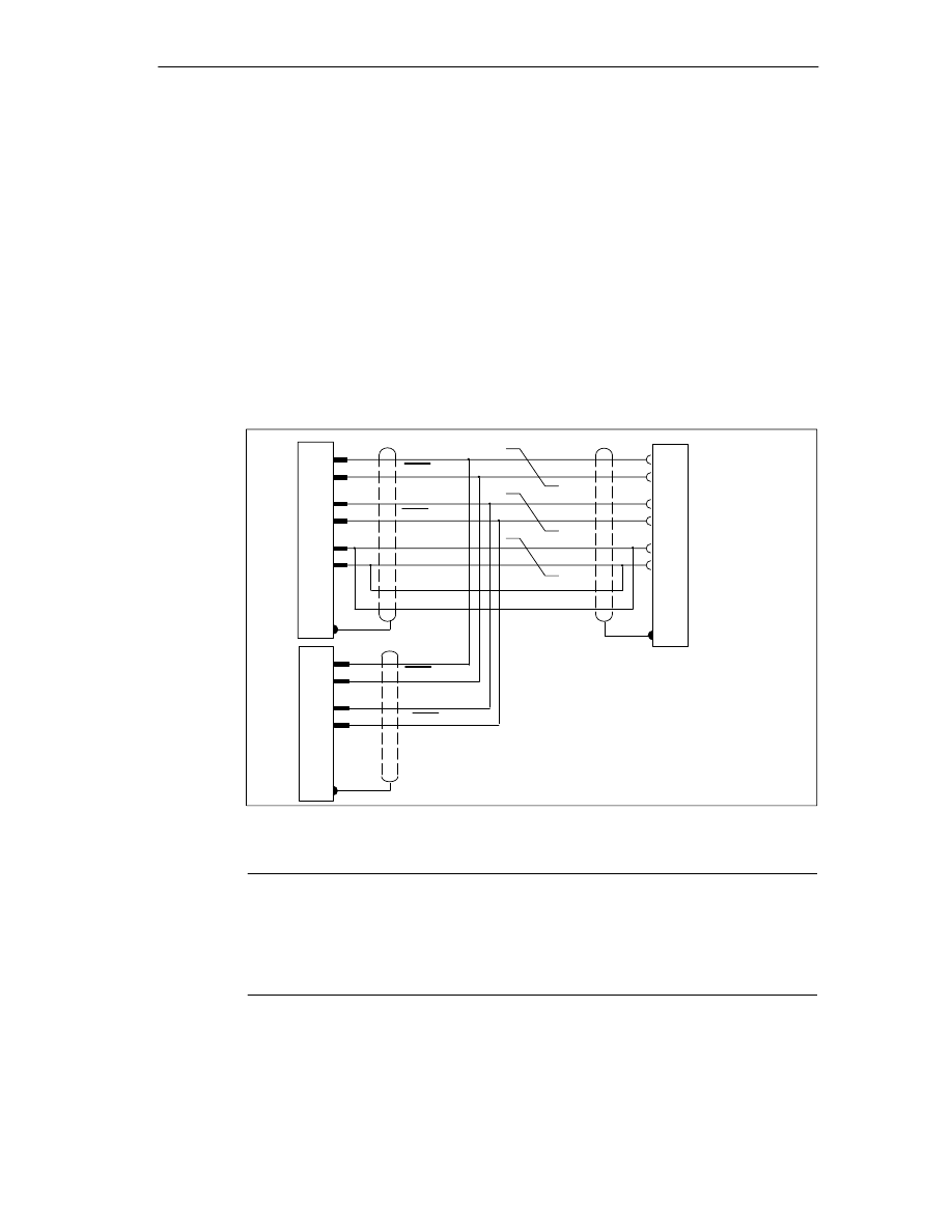
Encoders
10-7
FM 352 Electronic Cam Controller
C79000-G7076-C352-04
Listen-In
”Listen-In” means the following: An absolute encoder is operated in parallel on two
modules (for example FM 351 and FM 352). The FM 351 positioning module is the
master and the clocks the absolute encoder, and the FM 352 electronic cam
controller is the slave and listens in to the signals of the SSI frame.
Set ”Increments/Encoder Revolution” and “Number of Revolutions” to the master
setting. The transmission rate is irrelevant. Depending on the encoder type select
”Listen-In” or ”Listen-In Right-Justified” for ”Frame Length”.
Wiring Listen-In
Figure 10-3 based on the example of an FM 351 and FM 352 illustrates how to
connect the absolute encoder so that the FM 352 listens in.
15
14
2
3
7
5
DAT
CLS
red
blue
yellow
green
brown
white
pink
+24 V
Shield to
housing
Wires twisted in pairs
gray
Ground
DAT
CLS
15
14
13
12
DAT
DAT
Shield to
housing
Shield to
housing
Absolute encoder
FM 351 as master
FM 352 as slave
FM 352 ”listens in”
CLI
CLI
Must be connected to
encoder interface of master.
Figure 10-3
Connection of Absolute Encoders (SSI)
Note
If you want the FM 352 to listen in, you must connect the ground (M) of the
encoder power supply of the master (for example FM 351: front connector, pin 48)
and of the slave (FM 352: front connector, Pin 48) making low-resistance
connection with the ground of the CPU.

Encoders
10-8
FM 352 Electronic Cam Controller
C79000-G7076-C352-04
Reaction Times
With absolute encoders, the FM 352 has the following reaction times:
Minimum reaction time = frame run time + cam cycle + switching time of the connected switching elements
Maximum reaction time = frame run time + monostable flip-flop time + 2
cam cycle + switching time
of the connected switching elements
With programmable absolute encoders:
Maximum reaction time = frame run time + monostable flip-flop time + 2
cam cycle + switching time of the connected
switching elements +1/max. step train sequence
Monostable flip-flop time
The following limit values apply to the monostable flip-flop time:
•
Minimum monostable flip-flop period: > 15
s
•
Maximum monostable flip-flop time: < 64
s
Encoders with values outside the limits shown here are not permitted.
Frame run times
The frame run times depend on the baud rate:
Baud Rate
Frame Run Time for 13 bits
Frame Run Time for 25 bits
0.125 MHz
112
s
208
s
0.250 MHz
56
s
104
s
0.500 MHz
28
s
52
s
1.000 MHz
14
s
26
s
Example of Reaction Times
The following example shows how to calculate the minimum and maximum
reaction time. In the example a programmable encoder is not used.
•
Cam cycle: approx. 20
µ
s for max. 16 cams
•
Switching time of the hardware: approx. 150
µ
s
•
Frame run time: 26
µ
s at 1 MHz baud rate (25-bit frame)
•
Monostable flip-flop period: 20
µ
s (depends on the encoder: typical 20 to 40
µ
s)
Minimum reaction time = 26
µ
s + 20
µ
s + 150
µ
s = 196
µ
s
Maximum reaction time = 2
26
µ
s + 20
µ
s + 2
20
µ
s + 150
µ
s = 262
µ
s

Encoders
10-9
FM 352 Electronic Cam Controller
C79000-G7076-C352-04
Note
You can compensate the reaction time with appropriate parameter settings for the
cams or using dynamic adjustment.
Unsharpness
Unsharpness is the difference between the maximum and minimum reaction time.
With an Absolute encoder it is as follows:
Unsharpness =
1 cam cycle + frame run time + monostable flip-flop time
With programmable absolute encoders:
Unsharpness =
1 cam cycle + frame run time + monostable flip-flop time
+ 1/max. step train frequency
Note
If the switching time of the hardware on the FM 352 and the switching time of the
connected switching elements can be ignored, then reliable switching of the cam
is guaranteed if the cam is longer than the distance traveled within one cam cycle.

Encoders
10-10
FM 352 Electronic Cam Controller
C79000-G7076-C352-04
11-1
FM 352 Electronic Cam Controller
C79000-G7076-C352-04
Diagnostics
Chapter Overview
Section
Contents
Page
11.1
Possibilities for Error Evaluation
11.2
Meaning of the Error LEDs
11.3
Diagnostic Interrupts
11

Diagnostics
11-2
FM 352 Electronic Cam Controller
C79000-G7076-C352-04
11.1
Possibilities for Error Evaluation
•
With the programming device/PC, you can read out the diagnostic buffer with
the parameter assignment user interface using Test > Error Evaluation.
– You will see the error class and error number along with plain text.
•
You can evaluate errors in your program based on the following information:
– The return values (RET_VAL) of the linked FC as a group display for errors
that occurred while the FC was being executed.
– The error bits of the jobs as a group display for errors that occurred while
executing a job.
– The error bit DATA_ERR as a group display for an error detected by the
FM 352 during a write job.
– The error flag in JOB_ERR for the cause of the error in communication
between the FC and FM 352.
– FC CAM_DIAG for reading out the diagnostic buffer of the FM 352. Here,
you can find out the causes of errors in jobs and asynchronous events
(operating errors, diagnostic errors).
– Diagnostic interrupts for fast reaction to events.
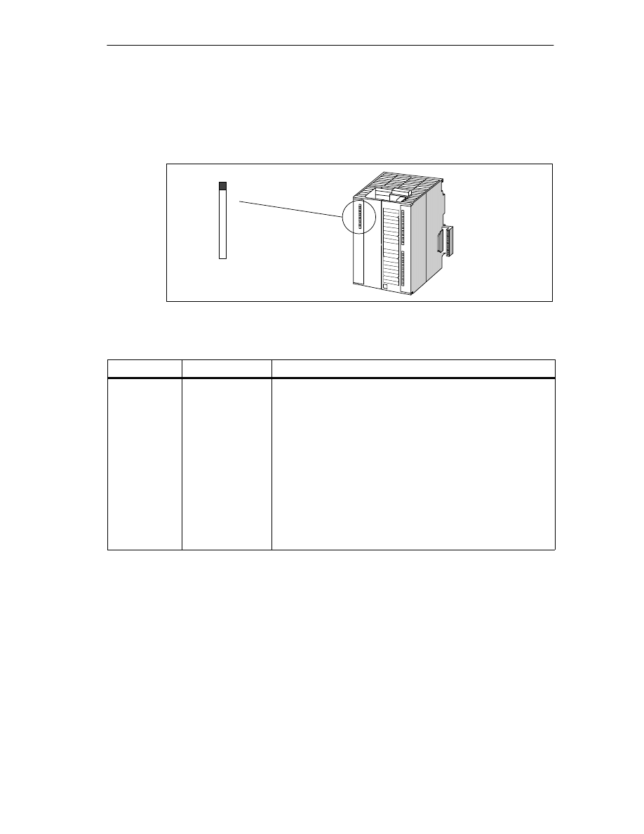
Diagnostics
11-3
FM 352 Electronic Cam Controller
C79000-G7076-C352-04
11.2
Meaning of the Error LEDs
The status and error displays indicate various error states. The LED is lit, even
with errors that occur briefly, for at least 3 seconds.
SF
Figure 11-1
Status and Fault/Error Indicator of the FM 352
Indicator
Meaning
Explanation
SF (red)
LED – ON
Group error for
internal and
external errors
This LED indicates the following error states on the FM 352:
•
Hardware interrupt lost
•
Watchdog expired
•
The FM 352 not configured.
•
Incorrect FM 352 parameter assignment (only when
parameters assigned with SDB)
•
No external 24 V auxiliary supply
•
No front connector
•
Encoder wire break
•
Operating error
•
Absolute encoder frame error
•
Incremental encoder pulse missing or zero marker missing

Diagnostics
11-4
FM 352 Electronic Cam Controller
C79000-G7076-C352-04
11.3
Diagnostic Interrupts
Interrupt Servicing
The FM 352 can trigger hardware interrupts and diagnostic interrupts. You service
these interrupts in an interrupt OB. If an interrupt is triggered and the
corresponding OB is not loaded, the CPU changes to STOP (refer to the manual
Programming with STEP 7).
You enable the servicing of diagnostic interrupts as follows:
1. Select the module in HW Config
2. Using the menu command Edit > Object Properties > Basic Parameters,
enable diagnostic interrupts.
3. Save and compile the hardware configuration.
4. Download the hardware configuration to the CPU.
Overview of the Diagnostic Interrupts
The following events and errors trigger a diagnostic interrupt:
•
Operating error
•
Incorrect machine data (when parameters assigned with SDB)
•
Incorrect cam data (when parameters assigned with SDB)
•
Diagnostic errors
These errors are explained in detail in Appendix C.4, page C-14 onwards.
Reaction of the FM 352 to an Error with a Diagnostic Interrupt
•
Cam processing is stopped
•
The synchronization is deleted with the following diagnostic interrupts:
– Front connector missing, external power supply missing
– A zero marker error was detected, cable fault (5 V encoder signals)
– The travel range was exceeded (indicated by an operating error)
– Set actual value cannot be executed (indicated by an operating error).
•
With one exception, control signals are no longer processed
Exception:
If the software limit switch is passed, a change in direction is still possible in the
simulation mode.
•
Function switches and jobs continue to be processed.

Diagnostics
11-5
FM 352 Electronic Cam Controller
C79000-G7076-C352-04
The FM 352 Detects an Error (“entering state”)
A diagnostic interrupt is “entering state” when at least one error is pending. If only
some of the errors are eliminated, the remaining pending errors are signaled again
as “entering state”.
Sequence:
1. The FM 352 detects one or more errors and initiates a diagnostic interrupt. The
“SF” LED is lit. The error is entered in the diagnostic buffer.
2. The CPU operating system calls OB82.
3. You can evaluate the start information of OB82.
4. With the OB82_MOD_ADDR parameter, you can see which module triggered
the interrupt.
5. You can obtain further information by calling FC CAM_DIAG.
The FM 352 Detects that an Error State is Cleared (“leaving state”)
A diagnostic interrupt is only “leaving state” when the last error on the module has
been rectified.
Sequence:
1. The FM 352 detects that all errors have been rectified and initiates a diagnostic
interrupt. The “SF” LED is no longer lit. The diagnostic buffer is not modified.
2. The CPU operating system calls OB82.
3. With the OB82_MOD_ADDR parameter, you can see which module triggered
the interrupt.
4. Evaluate the OB82_MDL_DEFECT bit.
If this bit is “0”, then no errors are present on the module. You can stop
evaluation here.
Diagnostic Interrupts Depending on the CPU Status
•
When the CPU is in the STOP state, diagnostic interrupts from the FM 352 are
disabled.
•
If none of the pending errors are eliminated while the CPU is in the STOP
mode, the FM 352 signals the errors that have not yet been eliminated as
“entering state” again when the CPU changes to RUN.
•
If all existing errors have been eliminated in the CPU STOP state, then the
error-free FM 352 state is not signaled with a diagnostic interrupt after the CPU
changes to RUN.

Diagnostics
11-6
FM 352 Electronic Cam Controller
C79000-G7076-C352-04

12-1
FM 352 Electronic Cam Controller
C79000-G7076-C352-04
Samples
Chapter Overview
Section
Contents
Page
12.1
Introduction
12.2
Requirements
12.3
Preparing the Samples
12.4
Code of the Samples
12.5
Testing a Sample
12.6
Adapting a Sample
12.7
Sample Program 1 “GettingStarted”
12.8
Sample Program 2 “Commission”
12.9
Sample Program 3 “OneModule”
12.10
Sample Program 4 “Interrupts”
12.11
Sample Program 5 “MultiModules”
12

Samples
12-2
FM 352 Electronic Cam Controller
C79000-G7076-C352-04
12.1
Introduction
When you install the FM 352/FM 452 software package, a sample project is also
installed that illustrates several typical applications based on a number of selected
functions.
The English sample project is in the following folder:
...\STEP7\EXAMPLES\zEn19_01
This contains several S7 programs of varying complexity and with different aims.
The programs include comprehensive comments.
12.2
Requirements
The following requirements must be met:
•
You have an S7 station consisting of a power supply module, a CPU and an
FM 452 or FM 352 module (Version
≥
V5) that is installed and wired up.
Earlier versions of the module may deviate from the behavior described.
•
You have correctly installed STEP 7 and the configuration package for the
FMx52 on your programming device/PC. The description of how to handle the
programs is based on STEP 7 V5.0. If you use a different version of STEP 7,
the procedures may differ slightly.
•
The programming device is connected to the CPU.
You can operate an FM 452 or an FM 352 with these samples. All the samples can
be executed with the FM 352 installed in a distributed configuration. To use the
“MultiModules” sample, you require two modules.

Samples
12-3
FM 352 Electronic Cam Controller
C79000-G7076-C352-04
12.3
Preparing the Samples
To be able work through the samples online, make the following preparations:
1. Open the sample project ...\STEP7\EXAMPLES\zEn19_01_FMx52___Prog
with the SIMATIC Manager and copy it to your project folder giving it a suitable
name.
2. Insert a station in this project to match your hardware configuration.
3. Configure the hardware completely with HW Config, save the configuration and
download it to the CPU.
4. Assign parameters for the FM 352 or FM 452 based on the “Getting Started”
manual.
5. Select a sample program and download its block folder to the CPU.
6. Select the FM 352 or FM 452 in the hardware configuration and display the
object properties (Edit > Object Properties).
7. Using the “Mod Addr
…
” dialog, enter the current module address in all offline
channel DBs and diagnostic DBs that exist in the sample program. Open the
dialog separately for each block.
You can also enter the module address with the LAD/STL/FBD editor in the
MOD_ADDR block parameter.
8. If you want to try out the next sample, go to step 5.
12.4
Code of the Samples
The samples are written in STL.
You can view them directly in the LAD/STL/FBD editor.
Select the view with “Symbolic Representation”, “Symbol Selection” and
“Comments”. If you have enough space on your screen, you can also display
“Symbol Information”.

Samples
12-4
FM 352 Electronic Cam Controller
C79000-G7076-C352-04
12.5
Testing a Sample
When you have made all the necessary entries for the sample, download the
complete block folder to the CPU.
The sample programs include variable tables (VATs) with which you can view and
modify the data blocks online (in other words in the RUN-P mode on the CPU). In
the variable table, select the views “Symbol” and “Symbol Comment”. Open a
variable table, link it with the configured CPU and monitor the variables cyclically.
This means that when the CPU is in the RUN-P or RUN mode, the displayed
variables are updated constantly.
All the samples require that the machine and cam data were entered and saved
with the parameter assignment user interface. This allows you to execute the
samples one after the other.
12.6
Adapting a Sample
The code of the samples in neither optimized nor designed for all eventualities.
Error evaluation is not programmed in detail in the sample programs to avoid the
programs becoming unwieldy.

Samples
12-5
FM 352 Electronic Cam Controller
C79000-G7076-C352-04
12.7
Sample Program 1 “GettingStarted”
Aim:
With this sample, you can put your cam controller into operation once you have
assigned parameters to it using the parameter assignment user interface based on
the “Getting Started” manual.
The sample extends the program shown in the “Linking in the User Program”
chapter of the primer by adding error evaluation.
Requirements:
You have assigned parameters for the cam controller as described in the
“Getting Started” primer.
The address of your module is entered correctly at the address MOD_ADDR in the
channel DB.
Startup:
In the startup OB (OB100) you call FC CAM_INIT that resets all the control and
return signals and the job management in the channel DB.
Cyclic Operation:
Open the variable table, establish the connection to the configured CPU and
monitor the variables. Transfer the prepared control values. The module changes
to the simulation mode. You can see how the actual value (CAM.ACT_POS) and
track signals (CAM.TRACK_OUT) change continuously.
Now change the simulation direction, specify different reference point coordinates,
turn off the simulation etc. by modifying and transferring the control values.

Samples
12-6
FM 352 Electronic Cam Controller
C79000-G7076-C352-04
Error Evaluation:
Produce a data error by entering a reference point coordinate greater than the end
of the rotary axis (for example 10000000). The CPU changes to STOP. (In a
sample, this is the simplest method of indicating an error. You can, of course,
program a more elegant method.)
Open the hardware configuration and double-click the FM 352 or FM 452. The
parameter assignment user interface is started. Display the cause of the error with
Test > Error Evaluation.
To eliminate the error, follow the steps outlined below:
1. Enter a permitted value in the control value.
2. Switch the CPU to STOP.
3. Switch the CPU to RUN-P.
4. Activate the control values. If you activate the control values before the CPU
restarts, they are reset by the initialization in OB100 and therefore have no
effect.

Samples
12-7
FM 352 Electronic Cam Controller
C79000-G7076-C352-04
12.8
Sample Program 2 “Commission”
Aim:
In this sample, you start up a cam controller without using the parameter
assignment user interface. You control and monitor using variable tables (VATs).
Requirements:
You have assigned parameters for the cam controller as described in the
“Getting Started” primer.
The address of your module has been entered in the block parameter MOD_ADDR
in the channel DB and diagnostic DB.
The supplied channel DB already contains the DB number (3) of the parameter DB
in the PARADBNO parameter.
The PARADB contained in the sample already has machine and cam data.
Startup:
In the startup OB (OB100), call FC CAM_INIT to initialize the channel DB. You
then set the trigger bits for all jobs and all control signals that you require after the
module starts.
Cyclic Operation:
Open the two variable tables (VAT1 and VAT2), establish the connection to the
configured CPU and monitor the variables.
In VAT1, you can see the changes in the actual position and the track signals. The
module is in operation.
In VAT2, you can see the most important entries of the diagnostic buffer of the
module. The meaning of the error classes and error numbers is described in the
manual in Appendix C.4, page C-14.
Change the machine and cam data in DB PARADB, download the DB to the CPU
and activate the control values in VAT1. The new data are written to the module
and activated. If the data contain errors, the error is indicated in VAT2. The
machine and cam data are described in the manual in Chapter 8, Page 8-2
onwards.

Samples
12-8
FM 352 Electronic Cam Controller
C79000-G7076-C352-04
Error Evaluation:
Attempt to create further errors:
•
Specify a reference point coordinate that is higher than the end of the rotary
axis.
•
Turn off the external power supply.
•
Delete PARADB on the CPU (online) and attempt to write machine data. (The
error evaluation is once again programmed [spitefully] so that the CPU changes
to STOP. If you update VAT1 again, the error code for this error is indicated in
CAM.JOB_ERR.)

Samples
12-9
FM 352 Electronic Cam Controller
C79000-G7076-C352-04
12.9
Sample Program 3 “OneModule”
Aim:
In this sample, you control a cam controller with a user program. The user program
starts up the module following a CPU warm restart. Afterwards, it executes a
series of steps that reacts to events.
Using the variable tables, you set the events, monitor the reactions of the module
and evaluate the diagnostic buffer.
In this somewhat more complex sample, you can get to know the following options
available with the blocks:
•
Specifying several jobs at the same time
•
Mixing write and read jobs
•
Reading using a permanent job without waiting for the end of the job
•
Evaluating the return signals of the block
•
Evaluating the return signals of an individual job
•
Resetting the done and error bits for individual or for all jobs
•
Central CAM_CTRL call at the end of the user program
•
Central error evaluation by CAM_DIAG at the end of the user program
•
Evaluation of the diagnostic buffer in conjunction with DATA_ERR
Requirements:
You have assigned parameters for the cam controller as described in the “Getting
Started” primer.
The address of your module has been entered in the block parameter MOD_ADDR
in the channel DB and diagnostic DB.
The supplied channel DB already contains the DB number (3) of the parameter DB
in the PARADBNO parameter.
The PARADB contained in the sample already has machine and cam data.
Startup:
In the startup OB (OB100) you set the startup flag (Step 0) for the user program in
the corresponding instance DB.

Samples
12-10
FM 352 Electronic Cam Controller
C79000-G7076-C352-04
Operation:
The CPU is in the STOP mode. Open the VAT1 variable table and transfer the
control values.
Start the CPU (STOP > RUN-P). You can see how the actual position
(CAM.ACT_POS), the cam data (CAM.CAM_00_31) and the track signals
(CAM.TRACK_OUT) change. You should also observe the step number of the step
sequence (PROGDB.STEPNO).
When cam 4 is set (130 degrees), cams 1 and 2 are assigned new parameter
values that were specified in VAT1. You can see the modification in the VAT.
The program then waits for an external event. Transfer the prepared control values
from the VAT again (this time PROGDB.SWITCH is evaluated). The cam data
return to the previous values again.
After this run through, the step sequence has been processed, the step number is
–2, and simulation is stopped.
If you want to repeat the entire sequence again, restart the CPU (STOP > RUN-P).
(This procedure is, of course, only acceptable in a sample.)
If you have not activated the PROGDB.SWITCH switch before a CPU STOP, the
parameters of the cam in the parameter DB are not set back to the original values.
You must then download the parameter DB to the CPU again.
Error Evaluation:
If an error occurs in execution, the step sequence is stopped and simulation
deactivated. The value –1 is entered as the step number.
Try to create cam errors that are entered in the PROGDB.CAM_ERR bit as group
errors by the central error evaluation.
•
Set cam positions in VAT1 that are higher than the end of the rotary axis.
•
Enter negative cam positions in VAT1.

Samples
12-11
FM 352 Electronic Cam Controller
C79000-G7076-C352-04
User Program (FB PROG):
The user program accesses the data in the module-specific data blocks with the
form <blockname>.<symbolic name>. This means that the user program can
operate exactly one module. The DB numbers specified when the user program is
called are simply passed on to supply FC CAM_CTRL and FC CAM_DIAG. With
this type of programming, you can access data in the data blocks using symbolic
names. Indirect addressing of more than one module is part of the sample program
5 “MultiModules”.
The user program executes a sequence of steps made up as follows:
Step 0: The cam controller is initialized. The jobs with the corresponding data are
set that will be executed when the module is started up. The restart of the module
can, for example,be triggered by a CPU warm restart or the return of a rack after a
rack failure.
Step 1: The program waits for the execution of the set jobs.
Step 2: The program reads the cam flag bits continuously and waits until cam 4 is
set.
Step 3: Cams 0 and 1 are assigned new parameter values. To allow you to see the
change, the cam data are read out before and after the change and displayed in
VAT1.
Step 4: The program waits for the execution of the set jobs.
Step 5: Here, the program waits for the “external” event “switch on”
(CAM.SWITCH = 1) that you can set with the VAT.
Step 6: When the event is recognized, cams 0 and 1 are set back to the value that
was read out in the initialization step.
Step 7: The program waits for the execution of the set jobs.
At the end of the step sequence, FC CAM_CTRL and FC CAM_DIAG are called. If
the diagnostics has detected a message about incorrect cam data, the output
CAM_ERR is set.

Samples
12-12
FM 352 Electronic Cam Controller
C79000-G7076-C352-04
12.10
Sample Program 4 “Interrupts”
Aim:
This sample contains a user program with the same task as in Sample program 3
“OneModule”. In this sample, we will show you how to evaluate a diagnostic
interrupt for certain modules and how to process this in the user program to
produce a general module error.
Requirements:
You have assigned parameters for the cam controller as described in the “Getting
Started” primer.
The address of your module has been entered in the block parameter MOD_ADDR
in the channel DB and diagnostic DB.
In the hardware configuration, enable the diagnostic interrupt for this module with
Edit > Object Properties > Basic Parameters > Select Interrupt > Diagnostics.
Compile the hardware configuration and download it to the CPU.
The supplied channel DB already contains the DB number (3) of the parameter DB
in the PARADBNO parameter.
The PARADB contained in the sample already has machine and cam data.
Startup:
In the startup OB (OB100), the startup flag (step 0) for the user program is set in
the instance DB.
Operation:
As in Sample program 3 “OneModule”.
Error Evaluation:
As in Sample program 3 “OneModule”.
Produce a diagnostic interrupt by disconnecting the power supply for the module or
by removing the front connector. The module error MOD_ERR and the diagnostic
error OB82_ERR are set to 1 and the step number becomes –1. When you
eliminate the problem, the error flags are also reset. Cam processing and
simulation, however, remain disabled.

Samples
12-13
FM 352 Electronic Cam Controller
C79000-G7076-C352-04
User Program (FB PROG):
The task is the same as in the Sample program 3 “OneModule”. The block was,
however, extended by adding evaluation of the diagnostic event.
In this sample, no special measures have been taken for restarting after
eliminating the error. We have left this up to you as part of the exercise.
Diagnostic Interrupt (OB82)
Depending on the address of the module that triggered the interrupt
(OB82_MDL_ADDR), the error ID in the corresponding instance DB of the user
program is entered in the diagnostic interrupt.

Samples
12-14
FM 352 Electronic Cam Controller
C79000-G7076-C352-04
12.11
Sample Program 5 “MultiModules”
Aim:
This sample contains the same user program as sample program 3 “OneModule”,
however it is used to operate two modules with different cam parameters. The
same copy of the user program is used for both modules. Naturally, each module
has its own set of data blocks.
Requirements:
You have plugged in two FMx52 modules and configured them in HW Config.
You have assigned parameters for both cam controllers as described in the
“Getting Started” primer.
The address of the relevant module has been entered in the block parameter
MOD_ADDR in the channel DBs and diagnostic DBs.
The supplied channel DBs already contain the DB number (3 or 13) of the
corresponding parameter DB in the PARADBNO parameter.
The parameter DBs DBs PARADB and PARADB2 contained in the sample contain
machine and cam data for both modules.
A set of variable tables is also prepared for each module.
Startup:
In the start up OB (OB100), you set the start up flag (Step 0) for the user program
in both instance DBs.
Operation:
The CPU is in the STOP mode. Open VAT1 and VAT11 and transfer their control
values.
Start the CPU (STOP > RUN-P). You can see how the actual positions, the cam
data, and the track signals of both modules change.
Error Evaluation:
As in Sample program 4 “Interrupts”, however separately for both modules.

Samples
12-15
FM 352 Electronic Cam Controller
C79000-G7076-C352-04
User Program (FB PROG):
The aim and sequence of the user program are as in Sample program 4
“Interrupts” and in Sample program 3 “OneModule”.
The user program is designed for the operation of more than one module since it
accesses the module-specific data blocks indirectly (channel DB, diagnostic DB,
and parameter DB). The DB numbers specified in the call are not only passed on
to supply FC CAM_CTRL and FC CAM_DIAG but are also used in the user
program. With this type of programming, you cannot use symbolic names for the
data in the data blocks.
Diagnostic Interrupt (OB82)
Depending on the address of the module that triggered the interrupt
(OB82_MDL_ADDR), the error ID in the corresponding instance DB of the user
program is entered in the diagnostic interrupt.

Samples
12-16
FM 352 Electronic Cam Controller
C79000-G7076-C352-04

A-1
FM 352 Electronic Cam Controller
C79000-G7076-C352-04
Technical Specifications
General Technical Data
The following technical specifications are described in the installation manual
S7-300 Programmable Controller, Installation and Hardware, CPU Specifications.
•
Electromagnetic compatibility
•
Transport and storage conditions
•
Mechanical and climatic ambient conditions
•
Details on insulation tests, class and level of protection.
UL/CSA Approvals
The following approvals exist for the S7-300:
UL Recognition Mark
Underwriters Laboratories (UL) conforming to
Standard UL 508, File E 116536
CSA Certification Mark
Canadian Standard Association (CSA) conforming to
Standard C 22.2 No. 142, File LR 48323
FM Approval
The following FM approval exists for the S7-300:
FM approval complying with Factory Mutual Approval Standard Class Number
3611, Class I, Division 2, Group A, B, C, D.
!
Warning
Injury to persons and damage to property may occur.
In areas subject to explosion hazards, persons may be injured and property
damaged if you disconnect lines to S7-300 during operation.
Electrically disconnect the S7-300 before separating plug connections in areas
subject to explosion hazards.
!
Warning
WARNING - DO NOT DISCONNECT WHILE CIRCUIT IS LIVE
UNLESS LOCATION IS KNOWN TO BE NON-HAZARDOUS
A
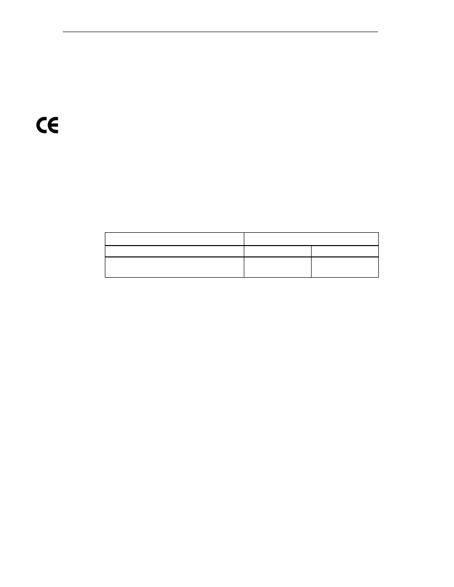
Technical Specifications
A-2
FM 352 Electronic Cam Controller
C79000-G7076-C352-04
CE Marking
Our products meet the requirements of the EU directive 89/336/EEC
”Electromagnetic Compatibility” and the harmonized European standards (EN)
listed in the directive.
In compliance with the above mentioned EU directive, Article 10, the conformity
declarations are available to the relevant authorities at the following address:
Siemens Aktiengesellschaft
Bereich Automatisierungstechnik
A&D AS E148
Postfach 1963
D-92209 Amberg
Area of Application
SIMATIC products are designed for use in an industrial environment.
Area of Application
Requirements
Emitted Noise
Noise Immunity
Industry
EN 50081-2 :
1993
EN 50082-2 :
1995
Adherence to Installation Instructions
SIMATIC products meet the requirements if you follow the installation instructions
described in manuals during both installation and operation.

Technical Specifications
A-3
FM 352 Electronic Cam Controller
C79000-G7076-C352-04
Technical Data
Dimensions and weight
Dimensions W
H
D (mm)
80
125
120
Weight
Approx. 530 g
Current, voltage and power
Current consumption (from the backplane bus)
max. 100 mA
Power dissipation
Typ. 8.1 W
Current consumption for encoders, digital inputs
and outputs from L+ (without load)
max. 200 mA (X1, terminal 1)
Supply of digital inputs and outputs
•
Supply voltage: 24 VDC
(permissible range: 20.4 to 28.8 V)
•
Permitted potential difference between input
ground connection M (X1, terminal 2)
•
and the central grounding point (shield):
60 V AC; 75 V DC
•
Insulation tested with 500 VDC
Encoder supply
•
Horizontal installation S7-300, 20
°
C:
•
5.2 V/300 mA
•
24 V/300 mA
•
Horizontal installation S7-300, 60
°
C:
•
5.2 V/300 mA
•
24 V/300 mA
•
Vertical installation S7-300, 40
°
C:
•
5.2 V/300 mA
•
24 V/300 mA
•
Encoder power supply 24 V, non-stabilized
(X2, terminal 5)
•
L+ -0.8 V
•
Short-circuit protection: yes, thermic
•
Encoder power supply 5.2 V (X2, terminal 6)
Short-circuit protection: yes, electronic
•
Permitted potential difference between input
(ground) and central ground connection of the
CPU: 1 V DC
Load voltage reverse polarity protection
No
Encoder inputs
Position detection
•
Incremental
•
Absolute
Signal voltages
•
Symmetrical inputs: 5 V to RS 422
•
Asymmetrical inputs:
24 V/typ. 9 mA
Input frequency and cable length for symmetrical
incremental encoders with 5 V supply
Max. 1 MHz for 32 m shielded cable length
Input frequency and cable length for symmetrical
incremental encoders with 24 V supply
Max. 1 MHz for 100 m shielded line length
Input frequency and cable length for asymmetrical
incremental encoder with 24 V supply
•
Max. 50 KHz for 25 m shielded cable length
•
Max. 25 KHz for 100 m shielded cable length

Technical Specifications
A-4
FM 352 Electronic Cam Controller
C79000-G7076-C352-04
Encoder inputs
Data transfer rate and cable length for absolute
encoders
•
Max. 125 KHz for 320 m shielded cable length
•
Max. 250 KHz for 160 m shielded cable length
•
Max. 500 KHz for 60 m shielded cable length
•
Max. 1 MHz for 20 m shielded cable length
Listen-in mode with absolute encoders
Yes
Input signals
•
Incremental: 2 pulse trains, 90
°
offset, 1 zero
pulse
•
Absolute: Absolute value
Digital inputs
Number of digital inputs
4
Number of simultaneously controllable digital inputs
4
Electrical isolation
No
Status indication
Yes, green LED per channel
Input voltage
•
0 signal: –30 V to 5 V
•
1 signal: 11 V to 30 V
Input current
•
0 signal:
≤
2 mA (closed-circuit current)
•
1 signal: 9 mA
Input delay
•
0
→
1 signal: max. 200
µ
s
•
1
→
0 signal: max . 200
µ
s
Connection of a 2-wire BERO
Possible
Unshielded cable length
32 m
Shielded line length
600 m
Switching frequency
max. 500 Hz
Insulation test
VDE 0160
Digital outputs
Number of outputs
13
Electrical isolation
No
Status indication
Yes, green LED per channel
Output current
•
0 signal: 0.5 mA
•
1 signal: 0.5 A at 100 % simultaneity
(permitted range: 5...600 mA)
•
Lamp load: 5 W
Output delay for output current 0.5 A
•
0
→
1 signal: max. 300
µ
s
•
1
→
0 signal: max. 300
µ
s
Signal level for 1 signal
L+: -0.8 V
Control of a digital input
Yes
Control of a counter input
no, due to 50
µ
s missing pulse
Short-circuit protection:
Yes, thermically clocked
Switching threshold 1.8 A
Limit on induct. cut-off voltage
Typ. L+ –48 V

Technical Specifications
A-5
FM 352 Electronic Cam Controller
C79000-G7076-C352-04
Digital outputs
Switching frequency
•
Resistive load: max. 500 Hz
•
Inductive load: Max. 0.5 Hz
Total current of digital outputs with S7-300
horizontal installation
Simultaneity factor 100 %:
•
at 20
°
C: 6 A
•
at 60
°
C: 3 A
Total current of digital outputs with S7-300 vertical
installation
Simultaneity factor 100 %:
at 40
°
C: 3 A
Unshielded cable length
Max. 100 m
Shielded line length
600 m
Insulation test
VDE 0160
Note
When the 24 V power supply is turned on using a mechanical contact, the FM 352 applies a
pulse to the outputs. Within the permitted output current range, the pulse may be 50
µ
s. You
must take this into account when you use the FM 352 in conjunction with fast counters.

Technical Specifications
A-6
FM 352 Electronic Cam Controller
C79000-G7076-C352-04

B-1
FM 352 Electronic Cam Controller
C79000-G7076-C352-04
Connection Diagrams
Overview
The following table describes encoders that you can connect to the FM 352. The
connection diagrams for these encoders are described in this chapter.
Section
Connection
Diagram for
Connecting Cable
Remark
Page
B.1
Incremental
encoder
4
2
0.25 + 2
1 mm
2
U
p
=5V, RS–422
Siemens
6FX 2001-2
B.2
Incremental
encoder
4
2
0.5 mm
2
U
p
=24V, RS–422
Siemens
6FX 2001-2
B.3
Incremental
encoder
4
2
0.5 mm
2
U
p
=24V, HTL
Siemens
6FX 2001-4
B.4
Absolute encoder
Siemens
4
2
0.5 mm
2
U
p
=24V, SSI
Siemens
6FX 2001-5
B
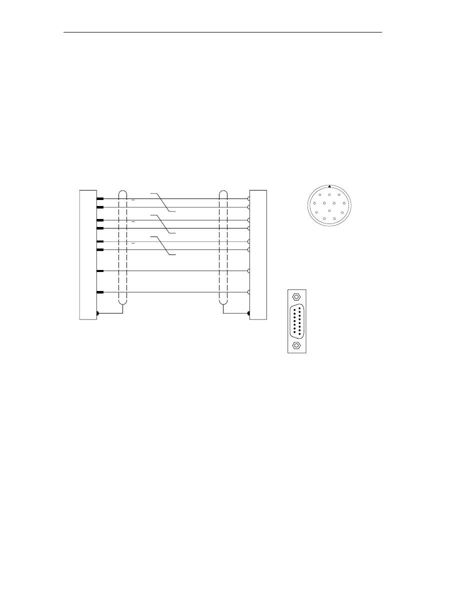
Connection Diagrams
B-2
FM 352 Electronic Cam Controller
C79000-G7076-C352-04
B.1
Connection Diagram for Incremental Encoder Siemens
6FX 2001-2 (U
p
=5V; RS 422)
Connection Diagram
The following schematic shows the connection diagram for the incremental
encoder Siemens 6FX 2001-2
(U
p
=5 V: RS422):
Wire 4
2
0,25 + 2
1 mm
2
Wires twisted in pairs
12-pin circular socket
Siemens 6FX 2003-0CE12
Pin side (soldered side)
1
2
3
4
5
6
7
8
9
10
11
12
15
14
13
12
10
11
7
6
5
6
8
1
3
4
10*
12**
11*
2**
A
A
B
B
N
N
FM 352
Encoder
Ground
+5,2 V
Shield to
casing
Shield to
casing
15-pin Cannon
connector
Pin side
(soldered side)
Metal housing
with screw locks
6FC9 341-1HC
15
9
8
1
* Pins 10 and 11 are jumpered internally.
** Pins 2 and 12 are jumpered internally.
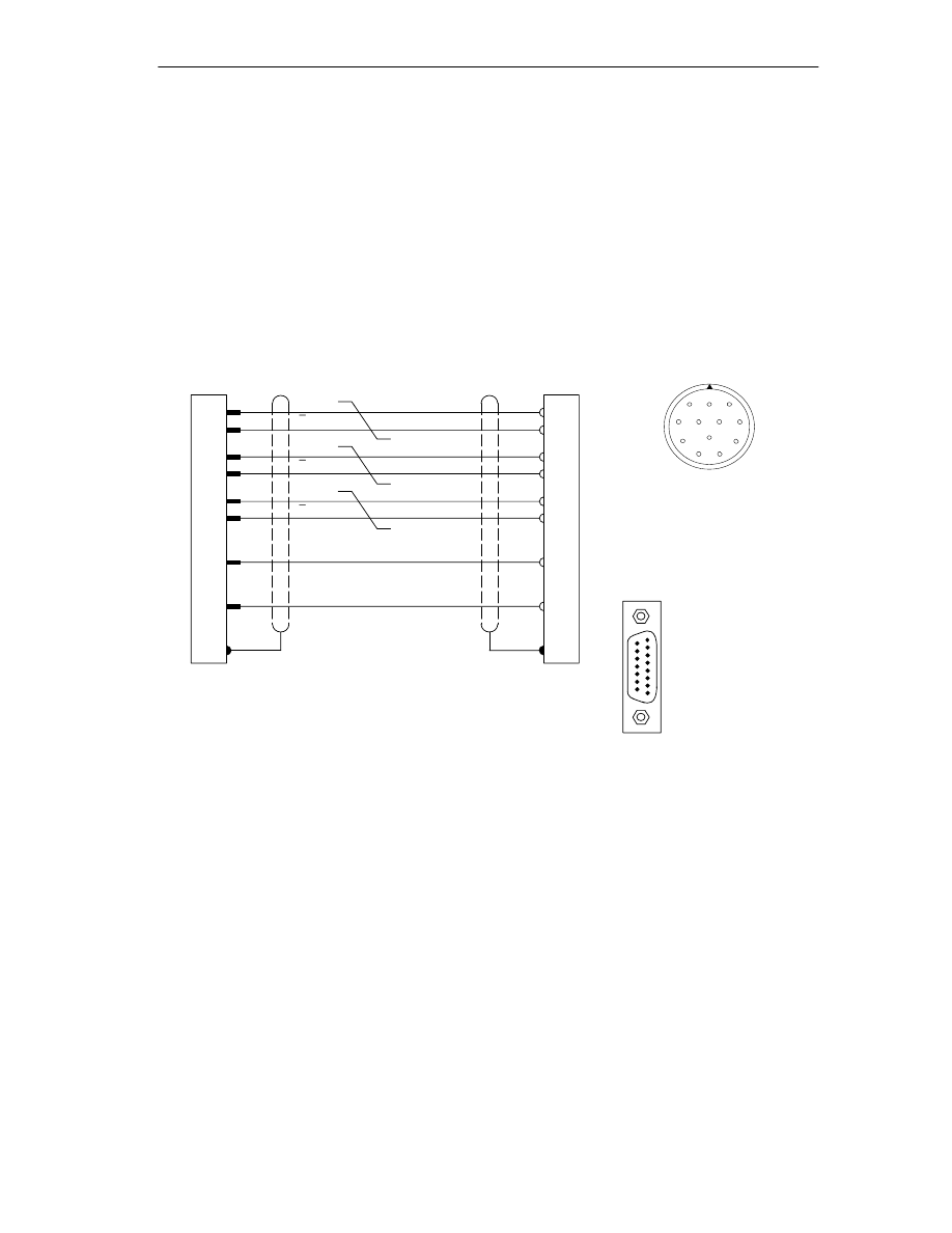
Connection Diagrams
B-3
FM 352 Electronic Cam Controller
C79000-G7076-C352-04
B.2
Connection Diagram for Incremental Encoder Siemens
6FX 2001-2 (Up=24V; RS 422)
Connection Diagram
The following illustration shows the connection diagram for the incremental
encoder Siemens 6FX 2001-2
(U
p
=24 V; RS 422):
Wire 4
2
0,5 mm
2
Wires twisted in pairs
Circular 12-pin socket
Siemens 6FX 2003-0CE12
Pin side (soldered side)
1
2
3
4
5
6
7
8
9
10
11
12
15
14
13
12
10
11
7
5
5
6
8
1
3
4
10*
12**
11*
2**
A
A
B
B
N
N
FM 352
Encoder
Ground
+24 V
Shield to
casing
Shield to
casing
15-pin Cannon
connector
Pin side (soldered side)
Metal housing
with screw locks
6FC9 341-1HC
15
9
8
1
* Pins 10 and 11 are jumpered internally.
** Pins 2 and 12 are jumpered internally.
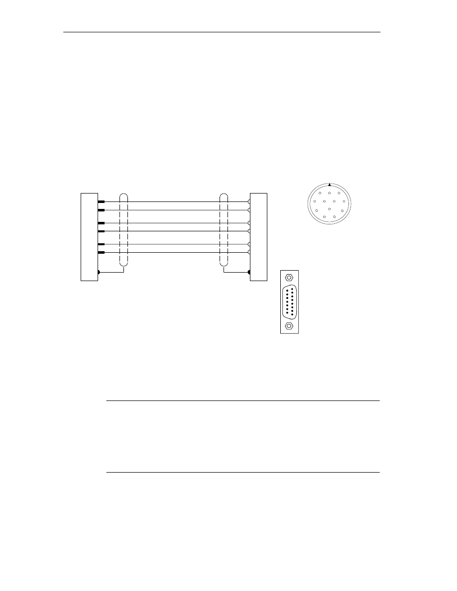
Connection Diagrams
B-4
FM 352 Electronic Cam Controller
C79000-G7076-C352-04
B.3
Connection Diagram for Incremental Encoder Siemens
6FX 2001-4 (Up=24V; HTL)
Connection Diagram
The following illustration shows the connection diagram for the incremental
encoder Siemens 6FX 2001-4
(Up=24 V; HTL):
Circular 12-pin socket
Siemens 6FX 2003-0CE12
Pin side (soldered side)
1
2
3
4
5
6
7
8
9
10
11
12
1
4
8
7
5
9
A*
B*
N*
FM 352
Encoder
Ground
Shield to
casing
Shield to
casing
Wire 4
2
0,5 mm
2
+24 V
RE
5
8
3
10*
12**
11*
15-pin Cannon
connector
Pin side (soldered side)
Metal housing with
screw locks
6FC9 341-1HC
15
9
8
1
2**
* Pins 10 and 11 are jumpered internally.
** Pins 2 and 12 are jumpered internally.
Note
If you would like to connect an incremental encoder from another manufacturer in
a push-pull configuration (current sourcing/sinking), then you must observe the
following:
•
Current sourcing: Connect RE (9) to ground (7).
•
Current sinking: Connect RE (9) to +24 V (5).
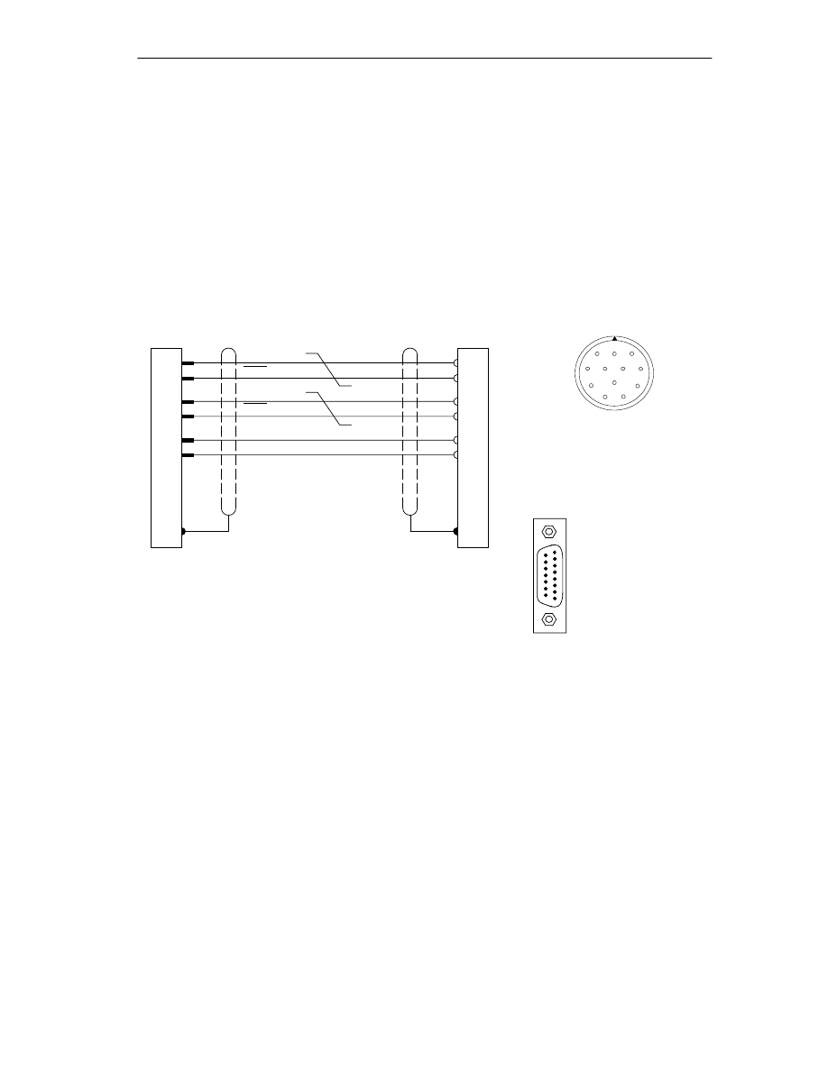
Connection Diagrams
B-5
FM 352 Electronic Cam Controller
C79000-G7076-C352-04
B.4
Connection Diagram for Absolute Encoder Siemens 6FX 2001-5
(Up=24V; SSI)
Connection Diagram
The following illustration shows the connection diagram for the absolute encoder
Siemens 6FX 2001-5
(Up=24 V; SSI):
Wires twisted in pairs
Circular 12-pin socket
Siemens 6FX 2003-0CE12
Pin side (soldered side)
1
2
3
4
5
6
7
8
9
10
11
12
15
14
2
3
7
5
CLS
FM 352
Encoder
+24 V
Shield to
casing
Wire 4
2
0,5 mm
2
Ground
CLS
DAT
DAT
3
4
2
1
12
11
15-pin Cannon
connector
Pin side (soldered side)
Metal housing with
screw locks
6FC9 341-1HC
15
9
8
1
Shield to
casing

Connection Diagrams
B-6
FM 352 Electronic Cam Controller
C79000-G7076-C352-04

C-1
FM 352 Electronic Cam Controller
C79000-G7076-C352-04
Data Blocks/Error Lists
Chapter Overview
Section
Contents
Page
C.1
Content of the Channel DB
C.2
Content of the Parameter DB
C.3
Data and Structure of the Diagnostic DB
C.4
Error Classes
C

Data Blocks/Error Lists
C-2
FM 352 Electronic Cam Controller
C79000-G7076-C352-04
C.1
Content of the Channel DB
Note
Do not modify data that are not listed in this table.
Table C-1
Content of the Channel DB
Address
Name
Type
Initial
Value
Comment
Addresses/Version Switch
0.0
MOD_ADDR (enter!)
INT
0
Module address
2.0
CH_NO
INT
1
Channel number (always 1)
10.0
PARADBNO
INT
-1
Number of the parameter DB
-1 = DB does not exist
12.0
FM_TYPE
BOOL
FALSE
0 = FM 352 up to V4.0
1 = FM 352 / FM 452 V5.0 or higher
Control signals
15.2
DIR_M
BOOL
FALSE
1 = simulation in negative direction
15.3
DIR_P
BOOL
FALSE
1 =
simulation in positive direction
15.4
CAM_EN
BOOL
FALSE
1 = enable cam processing
15.5
CNTC0_EN
BOOL
FALSE
1 = enable count function of counter cam
track 0
15.6
CNTC1_EN
BOOL
FALSE
1 = enable count function of counter cam
track 1
16.0
TRACK_EN
WORD
W#16#0
Enable cam tracks 0 to 15
Bit 0 = track 0
Return signals
22.2
DIAG
BOOL
FALSE
1 = diagnostic buffer modified
22.4
DATA_ERR
BOOL
FALSE
1 = data error
22.7
PARA
BOOL
FALSE
1 = module has parameters assigned
23.4
CAM_ACT
BOOL
FALSE
1 = cam processing active
25.0
SYNC
BOOL
FALSE
1 = axis is synchronized
25.1
MSR_DONE
BOOL
FALSE
1= length measurement or edge detection
completed
25.2
GO_M
BOOL
FALSE
1 = axis moving in negative direction
25.3
GO_P
BOOL
FALSE
1 = axis moving in positive direction
25.4
HYS
BOOL
FALSE
1 = axis within the hysteresis range
25.5
FVAL_DONE
BOOL
FALSE
1 = set actual value on-the-fly executed
26.0
ACT_POS
DINT
L#0
Current position of the axis

Data Blocks/Error Lists
C-3
FM 352 Electronic Cam Controller
C79000-G7076-C352-04
Table C-1
Content of the Channel DB
Address
Comment
Initial
Value
Type
Name
Return signals
30.0
TRACK_OUT
DWORD
DW#16#0 Current track signals tracks 0 to 31
Bit 0 = track 0
Function Switches
34.0
EDGE_ON
BOOL
FALSE
1 = edge detection on
34.1
SIM_ON
BOOL
FALSE
1 = simulation on
34.2
MSR_ON
BOOL
FALSE
1 = length measurement on
34.3
REFTR_ON
BOOL
FALSE
1 = retrigger reference point
34.4
SSW_OFF
BOOL
FALSE
1 = software limit switch off
Trigger Bits for Write Jobs
35.0
MDWR_EN
BOOL
FALSE
1 = write machine data
35.1
MD_EN
BOOL
FALSE
1 = activate machine data
35.2
AVALREM_EN
BOOL
FALSE
1 = cancel set actual value, set actual
value on-the-fly
35.3
CAM1WR_EN
BOOL
FALSE
1 = write cam data 1
(cam 0 to 15)
35.4
CAM2WR_EN
BOOL
FALSE
1 = write cam data 2
(cam 16 to 31)
35.5
CAM3WR_EN
BOOL
FALSE
1 = write cam data 3
(cam 32 to 47)
35.6
CAM4WR_EN
BOOL
FALSE
1 = write cam data 4
(cam 48 to 63)
35.7
CAM5WR_EN
BOOL
FALSE
1 = write cam data 5
(cam 64 to 79)
36.0
CAM6WR_EN
BOOL
FALSE
1 = write cam data 6
(cam 80 to 95)
36.1
CAM7WR_EN
BOOL
FALSE
1 = write cam data 7
(cam 96 to 111)
36.2
CAM8WR_EN
BOOL
FALSE
1 = write cam data 8
(cam 112 to 127)
36.3
REFPT_EN
BOOL
FALSE
1 = set reference point coordinates
36.4
AVAL_EN
BOOL
FALSE
1 = set actual value
36.5
FVAL_EN
BOOL
FALSE
1 = set actual value on-the-fly
36.6
ZOFF_EN
BOOL
FALSE
1 = set zero offset
36.7
CH01CAM_EN
BOOL
FALSE
1 = write cam edge setting (1 cam)
37.0
CH16CAM_EN
BOOL
FALSE
1 = write settings for fast cam parameter
change (16 cams)

Data Blocks/Error Lists
C-4
FM 352 Electronic Cam Controller
C79000-G7076-C352-04
Table C-1
Content of the Channel DB
Address
Comment
Initial
Value
Type
Name
Trigger Bits for Read Jobs
37.1
MDRD_EN
BOOL
FALSE
1 = read machine data
37.2
CAM1RD_EN
BOOL
FALSE
1 = read cam data 1
(cam 0 to 15)
37.3
CAM2RD_EN
BOOL
FALSE
1 = read cam data 2
(cam 16 to 31)
37.4
CAM3RD_EN
BOOL
FALSE
1 = read cam data 3
(cam 32 to 47)
37.5
CAM4RD_EN
BOOL
FALSE
1 = read cam data 4
(cam 48 to 63)
37.6
CAM5RD_EN
BOOL
FALSE
1 = read cam data 5
(cam 64 to 79)
37.7
CAM6RD_EN
BOOL
FALSE
1 = read cam data 6
(cam 80 to 95)
38.0
CAM7RD_EN
BOOL
FALSE
1 = read cam data 7
(cam 96 to 111)
38.1
CAM8RD_EN
BOOL
FALSE
1 = read cam data 8
(cam 112 to 127)
38.2
MSRRD_EN
BOOL
FALSE
1 = read measured values
38.3
CNTTRC_EN
BOOL
FALSE
1 = read count values of counter cam
tracks
38.4
ACTPOS_EN
BOOL
FALSE
1 = read position and track data
38.5
ENCVAL_EN
BOOL
FALSE
1 = read encoder values
38.6
CAMOUT_EN
BOOL
FALSE
1 = read cam and track data
Done Bits for Function Switches
40.0
EDGE_D
BOOL
FALSE
1 = “activate edge detection” or
“deactivate edge detection” completed
40.1
SIM_D
BOOL
FALSE
1 = “activate simulation” or “deactivate
simulation” completed
40.2
MSR_D
BOOL
FALSE
1 = “activate length measurement” or
“deactivate length measurement”
completed
40.3
REFTR_D
BOOL
FALSE
1 = “activate retrigger reference point” or
“deactivate retrigger reference point”
completed
40.4
SSW_D
BOOL
FALSE
1 = “activate software limit switch” or
“Deactivate software limit switch”
completed

Data Blocks/Error Lists
C-5
FM 352 Electronic Cam Controller
C79000-G7076-C352-04
Table C-1
Content of the Channel DB
Address
Comment
Initial
Value
Type
Name
Done Bits for Write Jobs
41.0
MDWR_D
BOOL
FALSE
1 = “write machine data” job completed
41.1
MD_D
BOOL
FALSE
1 = “enable machine data” job completed
41.2
AVALREM_D
BOOL
FALSE
1 = “cancel set actual value” or “cancel set
actual value on-the-fly” completed
41.3
CAM1WR_D
BOOL
FALSE
1 = “write cam data 1” job completed
41.4
CAM2WR_D
BOOL
FALSE
1 = “write cam data 2” job completed
41.5
CAM3WR_D
BOOL
FALSE
1 = “write cam data 3” job completed
41.6
CAM4WR_D
BOOL
FALSE
1 = “write cam data 4” job completed
41.7
CAM5WR_D
BOOL
FALSE
1 = “write cam data 5” job completed
42.0
CAM6WR_D
BOOL
FALSE
1 = “write cam data 6” job completed
42.1
CAM7WR_D
BOOL
FALSE
1 = “write cam data 7” job completed
42.2
CAM8WR_D
BOOL
FALSE
1 = “write cam data 8” job completed
42.3
REFPT_D
BOOL
FALSE
1 = “set reference point” job completed
42.4
AVAL_D
BOOL
FALSE
1 = A “set actual value” job completed
42.5
FVAL_D
BOOL
FALSE
1 = A “set actual value on-the-fly” job
completed
42.6
ZOFF_D
BOOL
FALSE
1 = “set zero offset” job completed
42.7
CH01CAM_D
BOOL
FALSE
1 = “change parameters for 1 cam” job
completed
43.0
CH16CAM_D
BOOL
FALSE
1 = “change parameters for 16 cams”
completed (fast cam parameter change)
Done Bits for Read Jobs
43.1
MDRD_D
BOOL
FALSE
1 = “read machine data” job completed
43.2
CAM1RD_D
BOOL
FALSE
1 = “read cam data 1” job completed
43.3
CAM2RD_D
BOOL
FALSE
1 = “read cam data 2” job completed
43.4
CAM3RD_D
BOOL
FALSE
1 = “read cam data 3” job completed
43.5
CAM4RD_D
BOOL
FALSE
1 = “read cam data 4” job completed
43.6
CAM5RD_D
BOOL
FALSE
1 = “read cam data 5” job completed
43.7
CAM6RD_D
BOOL
FALSE
1 = “read cam data 6” job completed
44.0
CAM7RD_D
BOOL
FALSE
1 = “read cam data 7” job completed
44.1
CAM8RD_D
BOOL
FALSE
1 = “read cam data 8” job completed
44.2
MSRRD_D
BOOL
FALSE
1 = “read measured values” job
completed
44.3
CNTTRC_D
BOOL
FALSE
1 = “read count values of counter cam
tracks” job completed
44.4
ACTPOS_D
BOOL
FALSE
1 = “read position and track data” job
completed

Data Blocks/Error Lists
C-6
FM 352 Electronic Cam Controller
C79000-G7076-C352-04
Table C-1
Content of the Channel DB
Address
Comment
Initial
Value
Type
Name
Done Bits for Read Jobs
44.5
ENCVAL_D
BOOL
FALSE
1 = “read current encoder value” job
completed
44.6
CAMOUT_D
BOOL
FALSE
1 = “read cam and track data” job
completed
Error Bits for Function Switches
46.0
EDGE_ERR
BOOL
FALSE
1 = error in “activate edge detection” or
“deactivate edge detection”
46.1
SIM_ERR
BOOL
FALSE
1 = error in “activate simulation” or
“deactivate simulation”
46.2
MSR_ERR
BOOL
FALSE
1 = error in “activate length measurement”
or “deactivate length measurement”
46.3
REFTR_ERR
BOOL
FALSE
1 = error in “activate retrigger reference
point” or “deactivate retrigger reference
point”
46.4
SSW_ERR
BOOL
FALSE
1 = error in “activate software limit switch”
or “deactivate software limit switch”
Error Bits for Write Jobs
47.0
MDWR_ERR
BOOL
FALSE
1 = error in “write machine data” job
47.1
MD_ERR
BOOL
FALSE
1 = error in “activate machine data” job
47.2
AVALREM_ERR
BOOL
FALSE
1 = error in “cancel set actual value” or
“cancel set actual value on-the-fly”
47.3
CAM1WR_ERR
BOOL
FALSE
1 = error in “write cam data 1” job
47.4
CAM2WR_ERR
BOOL
FALSE
1 = error in “write cam data 2” job
47.5
CAM3WR_ERR
BOOL
FALSE
1 = error in “write cam data 3” job
47.6
CAM4WR_ERR
BOOL
FALSE
1 = error in “write cam data 4” job
47.7
CAM5WR_ERR
BOOL
FALSE
1 = error in “write cam data 5” job
48.0
CAM6WR_ERR
BOOL
FALSE
1 = error in “write cam data 6” job
48.1
CAM7WR_ERR
BOOL
FALSE
1 = error in “write cam data 7” job
48.2
CAM8WR_ERR
BOOL
FALSE
1 = error in “write cam data 8” job
48.3
REFPT_ERR
BOOL
FALSE
1 = error in “set reference point” job
48.4
AVAL_ERR
BOOL
FALSE
1 = error in “set actual value” job
48.5
FVAL_ERR
BOOL
FALSE
1 = error in “set actual value on-the-fly” job
48.6
ZOFF_ERR
BOOL
FALSE
1 = error in “set zero offset” job
48.7
CH01CAM_ERR
BOOL
FALSE
1 = error in “change parameters for 1
cam” job
49.0
CH16CAM_ERR
BOOL
FALSE
1 = error in “change parameters for 16
cams” (fast cam parameter change)
Error Bits for Read Jobs

Data Blocks/Error Lists
C-7
FM 352 Electronic Cam Controller
C79000-G7076-C352-04
Table C-1
Content of the Channel DB
Address
Comment
Initial
Value
Type
Name
Error Bits for Read Jobs
49.1
MDRD_ERR
BOOL
FALSE
1 = error in “read machine data” job
49.2
CAM1RD_ERR
BOOL
FALSE
1 = error in “read cam data 1” job
49.3
CAM2RD_ERR
BOOL
FALSE
1 = error in “read cam data 2” job
49.4
CAM3RD_ERR
BOOL
FALSE
1 = error in “read cam data 3” job
49.5
CAM4RD_ERR
BOOL
FALSE
1 = error in “read cam data 4” job
49.6
CAM5RD_ERR
BOOL
FALSE
1 = error in “read cam data 5” job
9.7
CAM6RD_ERR
BOOL
FALSE
1 = error in “read cam data 6” job
50.0
CAM7RD_ERR
BOOL
FALSE
1 = error in “read cam data 7” job
50.1
CAM8RD_ERR
BOOL
FALSE
1 = error in “read cam data 8” job
50.2
MSRRD_ERR
BOOL
FALSE
1 = error in “read measured values” job
50.3
CNTTRC_ERR
BOOL
FALSE
1 = error in “read count values of counter
cam tracks” job
50.4
ACTPOS_ERR
BOOL
FALSE
1 = error in “read position and track data”
job
50.5
ENCVAL_ERR
BOOL
FALSE
1 = error in “read current encoder value”
job
50.6
CAMOUT_ERR
BOOL
FALSE
1 = error in “read cam and track data” job
Job Management for FC CAM_CTRL
52.0
JOB_ERR
INT
0
Communication error
54.0
JOBBUSY
BOOL
FALSE
1 = at least one job active
54.1
JOBRESET
BOOL
FALSE
1 = reset all error and done bits
Data for “Zero Offset” Job
86.0
ZOFF
DINT
L#0
Zero Offset
Data for “Set Actual Value” Job
90.0
AVAL
DINT
L#0
Coordinate for “set actual value”
Data for “Set Actual Value on-the-Fly” Job
94.0
FVAL
DINT
L#0
Coordinate for “set actual value on-the-fly”
Data for “Set Reference Point” job
98.0
REFPT
DINT
L#0
Coordinate for “set reference point”
Data for “Change Cam Edges” Job
102.0
CAM_NO
INT
0
Cam number
104.0
CAM_START
DINT
L#0
Cam start
108.0
CAM_END
DINT
L#0
Cam end
Data for the “Length Measurement/Edge Detection” Job
112.0
BEG_VAL
DINT
L#0
Initial Value

Data Blocks/Error Lists
C-8
FM 352 Electronic Cam Controller
C79000-G7076-C352-04
Table C-1
Content of the Channel DB
Address
Comment
Initial
Value
Type
Name
Data for the “Length Measurement/Edge Detection” Job
116.0
END_VAL
DINT
L#0
End value
120.0
LEN_VAL
DINT
L#0
Length
Data for the “Read Counted Values” Job
124.0
CNT_TRC0
INT
0
Current counter value for counter cam
track 0
126.0
CNT_TRC1
INT
0
Current counter value for counter cam
track 1
Data for the “Read Position and Track Data” Job
128.0
ACTPOS
DINT
L#0
Current position
132.0
ACTSPD
DINT
L#0
Current feedrate
136.0
TRACK_ID
DWORD
DW#16#0 Track flag bits of tracks 0 to 31
Data for the “Read Encoder Data” Job
140.0
ENCVAL
DINT
L#0
Encoder value
144.0
ZEROVAL
DINT
L#0
Counter reading at last zero mark
148.0
ENC_ADJ
DINT
L#0
Absolute Encoder Adjustment
Data for the “Read Cam and Track Data” Job
152.0
CAM_00_31
DWORD
DW#16#0 Cam flag bits for cams 0 to 31
156.0
CAM_32_63
DWORD
DW#16#0 Cam flag bits for cams 32 to 63
160.0
CAM_64_95
DWORD
DW#16#0 Cam flag bits for cams 64 to 95
164.0
CAM_96_127
DWORD
DW#16#0 Cam flag bits for cams 96 to 127
168.0
TRACK_ID1
DWORD
DW#16#0 Track flag bits of tracks 0 to 31
172.0
ACTPOS1
DINT
L#0
Current position
Data for the “Fast Cam Parameter Change” Job
176.0
C_QTY
BYTE
B#16#0
Number of cams to be modified
177.0
DIS_CHECK
BOOL
FALSE
1 =deactivate data check
180.0
CAM
ARRAY
[0...15]
STRUCT
Note:
The following structure must be
completed for each cam to be modified
Relative
Address
+0.0
CAM_NO
BYTE
B#16#0
Number of the cam to be modified
+1.0
C_EFFDIR
BOOL
FALSE
1 = change the activation direction
+1.1
C_CBEGIN
BOOL
FALSE
1 = change the cam start to the value
CBEGIN (new cam start)
+1.2
C_CEND
BOOL
FALSE
1 = change the cam end / on time to the
value CEND (new cam end)

Data Blocks/Error Lists
C-9
FM 352 Electronic Cam Controller
C79000-G7076-C352-04
Table C-1
Content of the Channel DB
Address
Comment
Initial
Value
Type
Name
Relative
Address
+1.3
C_LTIME
BOOL
FALSE
1 = change the lead time to the value
LTIME (new lead time)
+1.4
CAM_OFF
BOOL
FALSE
1 = deactivate the cam during the cam
data modification
+1.5
EFFDIR_P
BOOL
FALSE
1 = new activation direction positive (plus)
+1.6
EFFDIR_M
BOOL
FALSE
1 = new activation direction negative
(minus)
+2.0
CBEGIN
DINT
L#0
New cam start
+6.0
CEND
DINT
L#0
New cam end / new on time
+10.0
LTIME
INT
0
New lead time

Data Blocks/Error Lists
C-10
FM 352 Electronic Cam Controller
C79000-G7076-C352-04
C.2
Content of the Parameter DB
Note
Do not modify data that are not listed in this table.
Table C-2
Content of the Parameter DB
Address
Name
Type
Initial Value
Comment
Machine data
3.1
PI_MEND
BOOL
FALSE
0 for FM 352
3.2
PI_CAM
BOOL
FALSE
1: Enable hardware interrupt: Cam on/off
3.5
PI_MSTRT
BOOL
FALSE
0 for FM 352
4.0
EDGEDIST
DINT
L#0
Minimum edge-to-edge distance for edge
detection
8.0
UNITS
DINT
L#1
System of Units
12.0
AXIS_TYPE
DINT
L#0
0: Linear axis, 1: Rotary axis
16.0
ENDROTAX
DINT
L#100000
End of rotary axis
20.0
ENC_TYPE
DINT
L#1
Encoder type, frame length
24.0
DISP_REV
DINT
L#80000
Distance per encoder revolution
32.0
INC_REV
DINT
L#500
Increments per encoder revolution
36.0
NO_REV
DINT
L#1024
Number of encoder revolutions
40.0
BAUDRATE
DINT
L#0
Baud rate
44.0
REFPT
DINT
L#0
Reference point coordinate
48.0
ENC_ADJ
DINT
L#0
Absolute Encoder Adjustment
52.0
RETR_TYPE
DINT
L#0
Type of retrigger reference point
56.0
CNT_DIR
DINT
L#0
Count direction:
0: normal, 1: inverted
63.0
MON_WIRE
BOOL
TRUE
1: Wire break monitoring
63.1
MON_FRAME
BOOL
TRUE
1: Frame error monitoring
63.2
MON_PULSE
BOOL
TRUE
1: Missing pulse monitoring
64.0
SSW_STRT
DINT
L#-100000000
Start of software limit switch
68.0
SSW_END
DINT
L#100000000
End of software limit switch
76.0
C_QTY
DINT
L#0
Number of cams: 0, 1, 2, 3 = max. 16, 32, 64,
128 cams
80.0
HYS
DINT
L#0
Hysteresis
84.0
SIM_SPD
DINT
L#0
Simulation speed
90.0
TRACK_OUT
WORD
W#16#0
Control of track outputs:
0 = cam controller, 1 = CPU;
Bit number = track number
95.0
EN_IN_I3
BOOL
FALSE
Enable input I3

Data Blocks/Error Lists
C-11
FM 352 Electronic Cam Controller
C79000-G7076-C352-04
Table C-2
Content of the Parameter DB
Address
Comment
Initial Value
Type
Name
Machine data
95.1
EN_IN_I4
BOOL
FALSE
0 for FM 352
95.2
EN_IN_I5
BOOL
FALSE
0 for FM 352
95.3
EN_IN_I6
BOOL
FALSE
0 for FM 352
95.4
EN_IN_I7
BOOL
FALSE
0 for FM 352
95.5
EN_IN_I8
BOOL
FALSE
0 for FM 352
95.6
EN_IN_I9
BOOL
FALSE
0 for FM 352
95.7
EN_IN_I10
BOOL
FALSE
0 for FM 352
99.0
SPEC_TRC0
BOOL
FALSE
1 = track 0 is counter cam track
99.1
SPEC_TRC1
BOOL
FALSE
1 = track 1 is counter cam track
99.2
SPEC_TRC2
BOOL
FALSE
1 = track 2 is brake cam track
100.0
CNT_LIM0
DINT
L#2
Upper counter value for counter cam track 0
104.0
CNT_LIM1
DINT
L#2
Upper counter value for counter cam track 1
Cam data for cams 0 to 15 / 0 to 31 / 0 to 63 / 0 to 127
108.0
STRUCT
(12 bytes length per element)
Relative
Address
+0.0
CAMVALID
BOOL
FALSE
1: Cam valid
+0.1
EFFDIR_P
BOOL
TRUE
1: Activation direction positive (plus)
+0.2
EFFDIR_M
BOOL
TRUE
1: Activation direction negative (minus)
+0.3
CAM_TYPE
BOOL
FALSE
0: Distance cam, 1: Time cam
+0.4
PI_SW_ON
BOOL
FALSE
1: Hardware interrupt on activation
+0.5
PI_SW_OFF
BOOL
FALSE
1: Hardware interrupt on deactivation
+1.0
TRACK_NO
BYTE
B#16#0
Track number
+2.0
CBEGIN
DINT
L#-100000000
Cam start
+6.0
CEND
DINT
L#100000000
Cam end/activation time
+10.0
LTIME
INT
0
Lead time

Data Blocks/Error Lists
C-12
FM 352 Electronic Cam Controller
C79000-G7076-C352-04
C.3
Data and Structure of the Diagnostic DB
Note
Do not modify data that are not listed in this table.
Table C-3
Structure of the Diagnostic DB
Address
Name
Type
Initial Value
Comment
0.0
MOD_ADDR
(enter!)
INT
0
Module address
256.0
JOB_ERR
INT
0
Communication error
258.0
JOBBUSY
BOOL
FALSE
1 = job active
258.1
DIAGRD_EN
BOOL
FALSE
1 = read diagnostic buffer unconditional
260.0
DIAG_CNT
INT
0
Number of valid entries in the list
262.0
DIAG[1]
STRUCT
Diagnostic data latest entry
272.0
DIAG[2]
STRUCT
Diagnostic data second entry
282.0
DIAG[3]
STRUCT
Diagnostic data third entry
292.0
DIAG[4]
STRUCT
Diagnostic data oldest entry
The diagnostic entry DIAG[n] is structured as follows:
Table C-4
Structure of the Diagnostic Entry
Address
Name
Type
Initial Value
Comment
+0.0
STATE
BOOL
FALSE
0 = event entering state
1 = event leaving state
+0.1
INTF
BOOL
FALSE
1 = internal error
+0.2
EXTF
BOOL
FALSE
1 = external error
+2.0
FCL
INT
0
Error class:
1: Operating errors
4: Data errors
5: Machine data errors
7: Cam data errors
15: Messages
128: Diagnostic errors
+4.0
FNO
INT
0
Error number 0 to 255
+6.0
CH_NO
INT
0
Channel number (always 1)
+8.0
CAMNO
INT
0
Cam number 0 to 127 for error class = cam data
errors

Data Blocks/Error Lists
C-13
FM 352 Electronic Cam Controller
C79000-G7076-C352-04
List of JOB_ERR Messages
JOB_ERR
(hex)
JOB_ERR
(dec)
JOB_ERR
(int)
Meaning
80A0
32928
-32608
Negative acknowledgment when reading from module. Module
removed during read operation or module defective.
80A1
32929
-32607
Negative acknowledgment when writing to module. Module
removed during write operation or module defective.
80A2
32930
-32606
DP protocol error at layer 2
80A3
32931
-32605
DP protocol error at user interface / user
80A4
32932
-32604
Communication problem on K bus
80B1
32945
-32591
Specified length wrong. Incorrectly set FM_TYPE parameter in the
channel DB for the module in use.
80B2
32946
-32590
The configured slot is empty.
80B3
32947
-32589
Actual module type does not match configured module type.
80C0
32960
-32576
The module does not have the data to be read.
80C1
32961
-32575
The data of a write job of the same type have not yet been
processed on the module.
80C2
32962
-32574
The module is currently processing the maximum number of jobs.
80C3
32963
-32573
Required resources (memory etc.) currently in use.
80C4
32964
-32572
Communication error
80C5
32965
-32571
Distributed I/Os not available.
80C6
32966
-32570
Priority class abort (warm restart or background)
8522
34082
-31454
Channel DB or parameter DB too short. The data cannot be read
from the DB. (write job)
8532
34098
-31438
DB number of the parameter DB too high. (write job)
853A
34106
-31430
Parameter DB does not exist. (write job)
8544
34116
-31420
Error in nth (n > 1) read access to a DB after error occurred. (write
job)
8723
34595
-30941
Channel DB or parameter DB too short. The data cannot be written
to the DB. (read job)
8730
34608
-30928
Parameter DB on the CPU write-protected. The data cannot be
written to the DB (read job).
8732
34610
-30926
DB number of the parameter DB too high. (read job)
873A
34618
-30918
Parameter DB does not exist. (read job)
8745
34629
-30907
Error in nth (n > 1) write access to a DB after error occurred. (read
job)
The errors 80A2 to 80A4 and 80Cx are temporary; in other words, they can be cleared after a waiting time
without you taking any action. Messages in the form 7xxx indicate temporary states in communication.

Data Blocks/Error Lists
C-14
FM 352 Electronic Cam Controller
C79000-G7076-C352-04
C.4
Error Classes
Class 1: Operating Errors
Operating errors are detected asynchronous to operator input/commands.
No.
Meaning
Diagnostic
Interrupt
1
Software limit switch start passed
Yes
2
Software limit switch end passed
Yes
3
Travel range start passed
Yes
4
Travel range end passed
Yes
13
Set actual value on-the-fly cannot be executed
Yes
Cause
The software limit switches are outside the travel range
(-100m...+100m or -1000m...+1000m) after the set
actual value on-the-fly.
The shift resulting from set actual value / set actual
value on-the-fly is more than
100m or
1000m.
Effect
Axis not synchronized
Class 4: Data Errors
Data errors are detected synchronous to operator input/commands.
No.
Meaning
Diagnostic
Interrupt
10
Bad zero offset
No
Cause
The zero offset is more than
100m or
1000m.
The software limit switches are outside the travel range
(-100m...+100m or -1000m...+1000m) after setting the
zero offset.
Rotary axis: The value of the zero offset is higher than
the end of the rotary axis.
11
Bad actual value specified
No
Cause
Linear axis: the coordinate is outside the current
(possibly shifted) software limit switch.
Rotary axis: The coordinate is < 0 or higher than the
end of the rotary axis.
12
Bad reference point
No
Cause
Linear axis: the coordinate is outside the current
(possibly shifted) software limit switch.
Rotary axis: The coordinate is < 0 or higher than the
end of the rotary axis.

Data Blocks/Error Lists
C-15
FM 352 Electronic Cam Controller
C79000-G7076-C352-04
No.
Diagnostic
Interrupt
Meaning
20
Activate machine data not permitted
No
Cause
There are no new (error-free) machine data on the
module
21
Set actual value on-the-fly not permitted
No
Cause
An attempt was made to execute “set actual value
on-the-fly” while “retrigger reference point” was active.
27
Illegal bit-coded setting
No
Cause
Unused and, in this case, unwritten bits are not 0.
An attempt was made to select “length measurement”
and “edge detection” at the same time.
28
Retrigger reference point is not permitted
No
Cause
An attempt was made to execute “retrigger reference
point” while “set actual value on-the-fly” was active.
An attempt was made to execute “retrigger reference
point” with an SSI encoder.
29
Illegal bit-coded command
No
Cause
Unused and, in this case, unwritten bits are not 0.
30
Bad lead time
No
31
Bad cam number
No
Cause
The cam is not valid.
The cam number is not in the range 0 to 127.
32
Bad cam start
No
Cause
The cam start is outside the travel range
(-100m...+100m or -1000m...+1000m).
Rotary axis: The cam start is < 0 or higher than the end
of the rotary axis.
33
Bad cam end / bad activation time
No
Cause
The cam end is outside the travel range
(-100m...+100m or -1000m...+1000m) .
Rotary axis: The cam end is < 0 or higher than the end
of the rotary axis.
The cam is not active for at least the duration of a
pulse.
34
Cancel set actual value not possible
No
Cause
The actual position value would be outside the working
range with an SSI encoder and linear axis after making
the setting.

Data Blocks/Error Lists
C-16
FM 352 Electronic Cam Controller
C79000-G7076-C352-04
No.
Diagnostic
Interrupt
Meaning
35
Bad actual value specified for set actual value / set actual value
on-the-fly
No
Cause
The specified actual value is outside the permitted
numeric range of
100 m or
1000 m.
The software limit switches would be outside the travel
range (-100m...+100m or -1000m...+1000m) after
making the setting.
The shift resulting from set actual value / set actual
value on-the-fly would be more than
100 m or
1000 m.
107
Parameters not set for the axis
No
Cause
There are no machine data on the axis.
There are no machine data activated on the axis.
108
Axis not synchronized
No
Cause
One of the settings “set actual value”, “set actual value
on-the-fly”, and “retrigger reference point” was started
although the axis is not synchronized.
109
Cam processing running
No
110
Bad number of cams to be modified.
No

Data Blocks/Error Lists
C-17
FM 352 Electronic Cam Controller
C79000-G7076-C352-04
Class 5: Machine Data Errors
The diagnostic interrupt is triggered only when there is an error in the system data
block (SDB).
No.
Meaning
Diagnostic
Interrupt
5
Error in hardware interrupt setting
Yes
Cause
You have attempted to select a hardware interrupt that
the module does not support.
6
Bad minimum edge-to-edge distance
Yes
Cause
You have entered a value < 0 or > 10
9
µ
m as the
minimum edge-to-edge distance.
8
Bad axis type
Yes
Cause
You have specified neither 0 nor 1 as the axis type
9
Bad rotary axis end
Yes
Cause
The value for the end of the rotary axis is outside the
permitted range of 1 to 10
9
µ
m or 1 to 10
8
µ
m
(depending on the resolution).
10
Bad encoder type
Yes
Cause
The value for the encoder type is outside the permitted
range of 1 to 10.
11
Bad distance /encoder revolution
Yes
Cause
The value for distance /encoder revolution is outside
the permitted range of 1 to 10
9
µ
m (regardless of the
resolution).
13
Bad number of increments /encoder revolution (see Section 8.5
page 8-15)
Yes
14
Bad number revolutions (see Section 8.5 page 8-15)
Yes
15
Bad baudrate
Yes
Cause
You have specified a baudrate outside the permitted
range of 0 to 3.
16
Bad reference point coordinate
Yes
Cause
The coordinate is outside the range of -100m to +100m
or -1000m to +1000m depending on the resolution.
Linear axis: The coordinate is outside the working
range.
Rotary axis The coordinate is higher than the end of the
rotary axis or < 0.
17
Bad absolute encoder adjustment
Yes
Cause
SSI encoder: The value of the absolute encoder
adjustment is not in the encoder range (increments per
encoder revolution * number of revolutions - 1).
18
Bad type of retrigger reference point
Yes
Cause
You have specified a value other than 0, 1, 6 and 7.

Data Blocks/Error Lists
C-18
FM 352 Electronic Cam Controller
C79000-G7076-C352-04
No.
Diagnostic
Interrupt
Meaning
19
Bad direction adaptation
Yes
Cause
You have specified a value other than 0 and 1.
20
Hardware monitoring not possible
Yes
Cause
21
Bad software limit switch start
Yes
Cause
Linear axis: The software limit switch start is outside the
travel range (-100m...+100m or -1000m...+1000m,
depending on the resolution).
Linear axis: software limit switch start and end
including any existing zero offset) is less than -100 m or
-1000 m (depending on the resolution).
22
Bad software limit switch end
Yes
Cause
Linear axis: The software limit switch end is outside the
travel range (-100m...+100m or -1000m...+1000m,
depending on the resolution) or is less than the
software limit switch start.
The software limit switch end ( including any existing
zero offset) is higher than +100 m or +1000 m
(depending on the resolution).
144
Bad number of cams
Yes
Cause
You have specified a value other than 0 to 3 for the
number of cams.
145
Bad hysteresis
Yes
Cause
The hysteresis is outside the range
0...65535*resolution.
The hysteresis is higher than
¼
*working range or
¼
*rotary axis range.
146
Bad simulation speed
Yes
Cause
The simulation speed is outside the range 1000*RESO
to 3*10
7
*RESO or is higher than
5* 10
8
µ
m/min.
The simulation speed cannot be set internally.
147
Bad track
Yes
Cause
Activation of a track outside 0 to 15 (bits 0 to 15) was
selected.
148
Bad selection of the enable inputs
Yes
Cause
You wanted to enable a track outside 3 to 10 (bits 0 to
7) using an external signal.
149
Bad special track selection.
Yes
Cause
You wanted to define a track outside 0,1 and 2 (bits 0,1
and 2) as a special track

Data Blocks/Error Lists
C-19
FM 352 Electronic Cam Controller
C79000-G7076-C352-04
No.
Diagnostic
Interrupt
Meaning
150
Bad upper counter value for track 0
Yes
Cause
You have specified a counter value < 2 or > 65535 as
the upper counter value.
151
Bad upper counter value for track 1
Yes
Cause
You have specified a counter value < 2 or > 65535 as
the upper counter value.
200
Bad resolution
Yes
Cause
You have specified a resolution < 0.1
µ
m/pulse or
>1000
µ
m/pulse.
You have specified a distance/encoder revolution and a
number of pulses/encoder revolution, that results in a
resolution of < 0.1 or > 1000.
201
Encoder does not match the working range / rotary axis range
Yes
Cause
SSI encoder and rotary axis: The encoder does not
exactly cover the rotary axis range.
Linear axis: The encoder does not cover at least the
working range (including software limit switches).

Data Blocks/Error Lists
C-20
FM 352 Electronic Cam Controller
C79000-G7076-C352-04
Class 7: Cam Data errors
The diagnostic interrupt is triggered only when there is an error in the system data
block (SDB).
No.
Meaning
Diagnostic
Interrupt
1
Hardware interrupt not permitted
Yes
Cause
You want to specify a hardware interrupt for a cam with
a cam number > 7.
2
Bad track number
Yes
Cause
The track number is outside the range 0 to 31.
3
Bad cam start
Yes
Cause
The cam start is outside the travel range
(-100m...+100m or -1000m...+1000m).
Rotary axis The cam start is < 0 and/or higher than the
end of the rotary axis.
4
Bad cam end
Yes
Cause
The cam end is outside the travel range
(-100m...+100m or -1000m...+1000m) .
The cam is at least one pulse long.
Rotary axis The cam end is < 0 and/or higher than the
end of the rotary axis.
5
Bad activation time
Yes
Cause
The activation time is < 0
µ
s. The maximum time
depends on the number of cams: (see Section 8.9,
page 8-26).
6
Bad lead time
Yes
Cause
The lead time is < 0
µ
s or > 26000*100
µ
s.
50
Too many cam records
Yes
Cause
You wanted to enter more cam records than is possible
with this number of cams.
51
Axis in operation
Yes
Cause
You wanted to enter cam records while the cam
controller is active.
52
Parameters not set for the axis
Yes
Cause
You want to enter cam data although not machine data
are active yet.

Data Blocks/Error Lists
C-21
FM 352 Electronic Cam Controller
C79000-G7076-C352-04
Class 15: Messages
No.
Meaning
Diagnostic
Interrupt
1
Start of parameter assignment
No
Cause
The module has detected a parameter assignment by
a system data block.
2
End of parameter assignment
No
Cause
The module has processed the parameter assignment
by a system data block error-free.

Data Blocks/Error Lists
C-22
FM 352 Electronic Cam Controller
C79000-G7076-C352-04
Class 128: Diagnostic Errors
No.
Meaning
Diagnostic
Interrupt
4
External auxiliary voltage missing
Yes
Cause
External auxiliary 24 V voltage is not connected or has
failed, front connector missing
Effect
See Page 11-4
•
Cam processing switched off
•
Track outputs are switched off
•
With incremental encoders, synchronization is
deleted.
•
The FM 352 has not had parameters assigned
(return signal PARA = 0).
Rectification Make sure that the 24 V connection is correct. (If 24 V
connection is correct, then the module is defective.)
51
Watchdog expired
Yes
Cause
•
Strong interference on the FM 352.
•
Error in the FM 352.
Effect
•
Module is reset.
•
Provided that after resetting the module, no module
defect is detected, the module is ready for
operation again.
•
The module signals the expired WATCHDOG with
“incoming” and “outgoing”.
Rectification
•
Eliminate the interference.
•
Contact the relevant sales department who will
require details of the circumstances leading to the
error.
•
Replace the FM 352.
52
Internal module power supply failed
Yes
Cause
Error in the FM 352.
Effect
•
Module is reset.
•
Provided that after resetting the module, no module
defect is detected, the module is ready for
operation again.
Rectification Replace the FM 352.

Data Blocks/Error Lists
C-23
FM 352 Electronic Cam Controller
C79000-G7076-C352-04
No.
Diagnostic
Interrupt
Meaning
70
Hardware interrupt lost
Yes
Cause
A hardware interrupt event has been detected by the
FM 352 and cannot be signaled since the same event
has not yet been processed by the user program/CPU.
Effect
•
Cam processing switched off
•
Track outputs are switched off
•
With incremental encoders, synchronization is
deleted.
Rectification
•
Link OB40 into the user program
•
Check bus connection of the module
•
Deactivate process interrupt
•
Upgrade hardware and software to suit your
process requirements (for example faster CPU,
optimize user program)
144
Encoder wire break
Yes
Cause
•
Encoder cable cut or not plugged in.
•
Encoder has no quadrature signals.
•
Incorrect pin assignment.
•
Cable length too long.
•
Encoder signals short circuited.
Effect
•
Cam processing switched off
•
Track outputs are switched off
•
With incremental encoders, synchronization is
deleted.
Rectification
•
Check encoder cable.
•
Keep within encoder specification.
•
Monitoring can be temporarily suppressed at the
responsibility of the operator by setting appropriate
parameters in the parameter assignment user
interface.
•
Keep to the module technical data.

Data Blocks/Error Lists
C-24
FM 352 Electronic Cam Controller
C79000-G7076-C352-04
No.
Diagnostic
Interrupt
Meaning
145
Frame error absolute encoder
Yes
Cause
The frame traffic between FM 352 and the absolute
encoder (SSI) is incorrect or interrupted:
•
Encoder cable cut or not plugged in.
•
Incorrect encoder type
•
Encoder incorrectly set (programmable encoders)
•
Frame length incorrectly specified
•
Encoder supplies incorrect values (encoder
defective)
•
Interference on measuring system cable
•
Baud rate selected too high
Effect
•
Cam processing switched off
•
Track outputs are switched off
•
The last correct actual value remains unchanged till
the end of the next correct SSI transfer
Rectification
•
Check encoder cable.
•
Check the encoder.
•
Check the frame traffic between encoder and FM
352.
146
Missing pulses frame incremental encoder
Yes
Cause
•
Encoder monitoring has detected missing pulses.
•
Number of increments per encoder revolution is
incorrectly entered.
•
Encoder defective: Does not supply the specified
number of pulses.
•
Bad or missing zero marker.
•
Interference affecting the encoder cable.
Effect
•
Cam processing switched off
•
Track outputs are switched off
•
The synchronization is deleted.
Rectification
•
Enter the number of increments/encoder revolution
correctly.
•
Check the encoder and encoder cable.
•
Keep to shielding and grounding regulations.
•
Monitoring can be temporarily suppressed at the
responsibility of the operator by setting appropriate
parameters in the parameter assignment user
interface.

Index-1
FM 352 Electronic Cam Controller
C79000-G7076-C352-04
Index
A
Absolute encoder, 8-8
data transfer, 10-6
frame run time, 10-8
increments per encoder revolution, 8-17
monostable flip-flop time, 10-8
pulse evaluation, 10-6
reaction times, 10-8
Absolute encoder adjustment, 8-12
alternative, 8-14
data in the parameter DB, 8-12
definition, 8-12
determining, 8-12
example, 8-13
Absolute encoders, 10-6
Activation direction, 2-3, 8-26, 8-27
Activation of the track outputs, 8-23
Active length, 2-3
Actual lead time, 8-29
Actual value change, 9-2
Addresses, C-2
Adjustment, dynamic, 2-10
Adjustment of the coordinate system, length
Ambient temperature, 3-1
Application, typical, 1-2
Applying glue tracks, 1-3
Approbation.
See Approval
Approval
Area of application for SIMATIC, A-2
Areas of application, FM 352, 1-3
Assigning parameters, 7-3
Asymmetrical output signals, 10-2
AVAL, 9-4
AVAL_EN, 9-4
AVALREM_EN, 9-5
Axis data, 8-7
Axis synchronization, 7-4
Axis type, 8-7
AXIS_TYPE, 8-7
B
BAUDRATE, 8-18
BEG_VAL, 9-17
Block library, 6-2
Block templates, 6-2
Bounce-free switch, 9-15
Brake cam track, 2-7, 8-24
C
C_CBEGIN, 9-13
C_CEND, 9-13
C_EFFDIR, 9-13
C_LTIME, 9-13
C_QTY, 8-23, 9-13
Cable length, maximum, 8-18
Calculating coordinate, zero offset, 9-6
Cam
change of direction, 2-9
deactivating, 9-14
direction-dependent, 2-2
shortest, 8-28
switching response, 8-26
Cam activation, condition, 2-3
Cam and track data, 9-28
Cam controller, 1-5

Index
Index-2
FM 352 Electronic Cam Controller
C79000-G7076-C352-04
Cam cycle time, 8-23, 8-29
Cam data, 8-1, 8-26
activation direction negative (minus), 8-27
activation direction positive (plus), 8-27
cam end, 8-28
cam start, 8-28
cam valid, 8-27
definition, 8-26
distance cam, 8-27
hardware interrupt on activation, 8-25, 8-27
hardware interrupt on deactivation, 8-25,
lead time, 8-29
on time, 8-28
reading, 8-4
time cam, 8-27
track number, 8-27
writing, 8-4
Cam data error, C-20
Cam data in the parameter DB, 8-27
Cam deactivation, condition, 2-3
Cam end, 8-28
Cam parameter change, 9-13
Cam start, 8-28
Cam tracks, 2-4
Cam types, 2-2
CAM_END, 9-11
CAM_NO, 9-11, 9-13
CAM_OFF, 9-13
CAM_START, 9-11
CAM_TYPE, 8-27
Cams, 2-2
CAMVALID, 8-27
CAMxRD_EN, 8-4
CAMxWR_EN, 8-4
Cancel set actual value, 9-3
Canceling the setting, canceling actual value
CBEGIN, 8-28, 9-13
CE, mark, iv
CE marking, A-2
CEND, 8-28, 9-13
CH01CAM_EN, 9-11
CH16CAM_EN, 9-13
Change cam edges, 9-11
canceling, 9-12
data used in the channel DB, 9-11
definition, 9-11
effects, 9-12
requirements, 9-11
sequence, 9-11
Change of direction
preparing, 7-5
structure, 6-12
task, 6-12
CNT_DIR, 8-19
CNT_LIM0, 8-24
CNT_LIM1, 8-24
Connecting an encoder, 4-3
Connecting cords, 4-6
Connection diagrams, B-1
Control signals, C-2
transferring, 6-5
writing, 6-19
Control signals for the cam controller, 9-29
data used in the channel DB, 9-29
sequence, 9-29
Controlling a press, 1-3
Count direction, 8-19
Counted values of the counter cam tracks
data used in the channel DB, 9-25
data used in the parameter DB, 9-25
sequence, 9-25
Counter cam track, 2-6, 2-10, 8-24
Counter cam tracks, counted values, 9-25
CPU, startup, 6-7
Creating a project, 7-2
CSA, A-1
Current consumption, 3-1
D
Data error, C-14
Data for ”change cam edges” job, C-7
Data for ”set actual value on–the–fly” job, C-7
Data for ”set actual value” job, C-7
Data for ”set reference point” job, C-7
Data for ”zero offset” job, C-7
Data for the ”fast cam parameter change” job,
Data for the ”length measurement/edge

Index
Index-3
FM 352 Electronic Cam Controller
C79000-G7076-C352-04
Data for the ”read position and track data” job,
DC power supply, 4-5
Deactivate software limit switches
Deactivating software limit switches,
SSW_OFF, 9-22
Delay time, total, 2-10
Diagnostic DB, 6-13
preparing, 7-5
structure, 6-13, C-12
task, 6-13
Diagnostic error, C-22
Diagnostic interrupt, evaluating, 6-15
Diagnostic interrupts, 11-4
entering state, 11-5
leaving state, 11-5
overview, 11-4
reaction of the FM 352, 11-4
Digital inputs, 4-5
Digital outputs, 4-5
DIR_M, 9-23
DIR_P, 9-23
Direct access to return signals, 6-18
Direction detection, 2-2
Direction of movement, 2-2
Direction-dependent cam, 2-2
DIS_CHECK, 9-13
DISP_REV, 8-16
Distance cam, 2-2
definition, 2-3
minimum length, 8-28
switching response, 8-26
with hysteresis, 8-10
Distance per encoder revolution, 8-16
Done bits for function switches, C-4
Done bits for read jobs, C-5
Done bits for write jobs, C-5
Dynamic adjustment, 2-10, 8-30
E
Edge acquisition, 9-15
Edge detection, requirements, 9-15
Edge-to-edge distance
EDGE_ON, 9-17
EDGEDIST, 8-11, 9-17
EFFDIR_M, 8-27, 9-13
EFFDIR_P, 8-27, 9-13
Electronic cam controller, 1-2, 1-4
EMERGENCY STOP limit switch, 4-1, 7-1
EMERGENCY STOP switch, 4-1, 7-1
EN_IN_I3, 8-24
Enable input, 8-24
ENC_ADJ, 8-12
ENC_TYPE, 8-15
Encoder, 4-3
machine data, 8-15
mechanical adjustment, 8-14
multi-turn, 10-6
single-turn, 10-6
total number of steps, 8-18
data used in the channel DB, 9-27
requirements, 9-27
sequence, 9-27
Encoder interface, 4-2
Encoder power supply , 4-5
Encoder range, 8-9
Encoder type, 8-15
ENCODER X2, 4-2
End of rotary axis, 8-7
End software limit switch, 8-9
END_VAL, 9-17
ENDROTAX, 8-7
Error bits for function switches, C-6
Error bits for read jobs, C-6
Error bits for write jobs, C-6
Error classes, C-14
Error evaluation, 11-2
Error LEDs, 11-3
Execution times, 6-17
External enable, 2-5, 8-24
External errors, 11-3
F
Fast access to module data, 6-18
Fast cam change, effects, 9-14
Fast cam parameter change, 9-13
canceling, 9-14
data check, 9-14
data used in the channel DB, 9-13
definition, 9-13
requirements, 9-13
sequence, 9-13
FC 0, FC CAM_INIT, 6-4
FC 1, FC CAM_CTRL, 6-5
FC 2, FC CAM_DIAG, 6-10

Index
Index-4
FM 352 Electronic Cam Controller
C79000-G7076-C352-04
call, 6-5
call parameters, 6-7
data used, 6-5
response to errors, 6-9
return values, 6-7
tasks, 6-5
call, 6-10
data used, 6-10
parameters, 6-10
response to errors, 6-11
return values, 6-11
tasks, 6-10
FC CAM_INIT, 6-4
call, 6-4
parameters, 6-4
return values, 6-4
tasks, 6-4
Feedrate, relationship with resolution, 8-22
Ferrules, 4-6
FM 352
areas of application, 1-3
installing, 3-2
removing, 3-2
startup, 6-7
Frame error, 8-19
Frame length, 8-15
Front connector, 4-4
Function switch, C-3
Function switches, 6-6
Functions, 6-2
execution times, 6-17
installing, 5-1
technical specifications, 6-16
FVAL, 9-4
FVAL_DONE, 9-4
FVAL_EN, 9-4
G
H
Hardware installation, 7-2
Hardware interrupt, 8-25
Horizontal installation, 3-1
HYS, 8-9
Hysteresis, 2-8, 8-9
distance cam, 8-10
time cam, 8-10
I
INC_REV, 8-17
Incorrect length measurement, 9-18
Increment, 10-3
Incremental encoder, 8-8
increments per encoder revolution, 8-17
missing pulses, 8-19
reaction times, 10-3
signal shapes, 10-2
Incremental encoders, 10-2
Increments per encoder revolution, 8-17
Initial parameter assignment, 8-2
Initiator, 8-8, 10-5
increments per encoder revolution, 8-17
signal evaluation, 10-5
functions, 5-1
parameter assignment user interface, 5-1
Installation instructions, A-2
Installation of the rail, 3-1
Interfaces of the cam controller, 2-11
Internal errors, 11-3
Interrupt enable, 8-25
cam data for, 8-25
definition, 8-25
machine data in the parameter DB, 8-25
J
Job, execute, 6-5
Job management for FC CAM_CTRL, C-7
Job status, 6-8
Jobs, 6-6
L

Index
Index-5
FM 352 Electronic Cam Controller
C79000-G7076-C352-04
LED, ”SF”, 11-3
LEN_VAL, 9-17
Length measurement, 9-15
data update, 9-16
incorrect, 9-18
minimum, 9-17
requirements, 9-15
result, 9-16
relevant for safety, 7-2
Linear axis, 1-2, 8-7, 8-8
Linear measure, 8-18
Listen, 8-15
Listen–in, 10-7
Listen-in
frame length / type, range of values, 10-6
increments per encoder revolution, 8-17
Location of the front connector, 4-4
Loss of synchronization, 9-8
LTIME, 8-29, 9-13
M
Machine and cam data, order when writing, 8-5
Machine data, 8-1
absolute encoder adjustment, 8-12
activating, 8-2, 8-3
activation of the track outputs, 8-23
axis, 8-7
axis type, 8-7
baud rate, 8-18
changing, 8-2
count direction, 8-19
distance per encoder revolution, 8-16
enable hardware interrupt: cam on/off, 8-25
enable input, 8-24
encoder type, 8-15
end of rotary axis, 8-7
end software limit switch, 8-9
frame length, 8-15
hysteresis, 8-9
increments per encoder revolution, 8-17
minimum edge-to-edge distance, 8-11
monitoring, 8-19
number of encoder revolutions, 8-18
reading, 8-3
reference point coordinate, 8-8
simulation speed, 8-11
special tracks, 8-24
start software limit switch, 8-9
type of reference point retriggering, 8-8
upper counter value counter cam track,
Machine data error, C-17
Machine data of the encoder, 8-15
data in the parameter DB, 8-15
definition, 8-15
Maximum cable length, 8-18
MD_EN, 8-3
MDRD_EN, 8-3
MDWR_EN, 8-3
Mechanical transmission elements, 1-4
Messages, C-21
Minimum edge-to-edge distance, 8-11
Minimum length measurement, 9-17
Missing pulses, incremental encoder, 8-19
Module cycle, 6-16
Module data, fast access, 6-18
MON_FRAME, 8-19
MON_PULSE, 8-19
MON_WIRE, 8-19
Monitoring, 8-19
Motor, 1-4
MSR_DONE, 9-17
MSR_ON, 9-17
MSRRD_EN, 9-17
Multi-turn encoder, 10-6
frame length / type, range of values, 10-6
Multi-turn encoder, increments per encoder
N
NO_REV, 8-18
Number of cams, 8-23
O
OB40_POINT_ADDR, content, 6-14
On time, 2-3, 8-28
Operating errors, C-14

Index
Index-6
FM 352 Electronic Cam Controller
C79000-G7076-C352-04
Order when writing, machine and cam data,
Output signal
asymmetrical, 10-2
symmetrical, 10-2
P
Packaging system, 1-3
Parameter assignment, requirements, 5-1
Parameter assignment user interface, 5-1, 7-3
areas, 6-13
structure, 6-13
task, 6-13
Parameter settings, distance/time cams, 2-3
Parameters relevant for synchronization, 8-3
PI_CAM, 8-25
PI_SW_OFF, 8-25, 8-27
PI_SW_ON, 8-25, 8-27
Pinout of the front connector, 4-4
Polarity of the encoder supply , 4-6
Position and track data, 9-26
data used in the channel DB, 9-26
sequence, 9-26
Power controller, 1-4
Power supply, 4-5
Preparations for programming, 7-5
Programming, 6-1
Proximity switches, 10-5
Pulses, 10-3
Putting into operation, 7-1
R
Rail, 3-1
Reference point coordinate, 8-8
REFPT, 8-8, 9-9, 9-20
REFPT_EN, 9-9
REFTR_ON, 9-20
retrigger reference point, 9-19
calculation, 8-20
definition, 8-20
example, 8-21
range of values, 8-21
Retrigger reference point
effects, 9-20
REFTR_ON, 9-19
requirements, 9-19
zero offset, 9-21
Return signals for diagnostics, 9-31
data used in the channel DB, 9-31
sequence, 9-31
Return signals for the cam controller, 9-30
data used in the channel DB, 9-30
sequence, 9-30
S
Safety mechanism, 1-4
Safety rule, 4-1
Safety rules, 3-1
Safety system, 1-4
Safety-relevant limit switches, 7-2
Samples, using, 12-3
Set actual value, 9-3, 9-5
data in the channel DB, 9-4
effects, 9-4
requirements, 9-3
sequence, 9-3
Set actual value on-the-fly, 9-3
data in the channel DB, 9-4
requirements, 9-3
sequence, 9-3
data used in the channel DB, 9-9
definition, 9-9
effects, 9-9
note on absolute encoders, 9-10
requirements, 9-9
sequence, 9-9
Setting
cancel set actual value, 9-3
change cam edges, 9-11
fast cam parameter change, 9-13
set actual value, 9-3
set actual value on-the-fly, 9-3
set reference point, 9-9
zero offset, 9-6

Index
Index-7
FM 352 Electronic Cam Controller
C79000-G7076-C352-04
Shortest cam, 8-28
Signal period, 10-3
SIM_ON, 9-23
SIM_SPD, 8-11, 9-23
Simulation
effects of activating, 9-23
effects of deactivating, 9-24
limit values, 9-24
sequence, 9-23
SIM_ON, 9-23
Simulation speed, 8-11, 9-23
Single-turn encoder, 10-6
frame length / type, range of values, 10-6
Single-turn encoder, increments per encoder
Slot, 3-1
SPEC_TRC0, 8-24
SPEC_TRC1, 8-24
SPEC_TRC2, 8-24
Special track, requirements, 2-6
Special tracks, 2-6, 8-24
SSW_END, 8-9, 9-22
SSW_OFF, 9-22
SSW_STRT, 8-9, 9-22
Standard units, 8-6
Start software limit switch, 8-9
Status and Fault/Error Indicators, 11-3
Step train frequency, 10-9
Sub D connector, 4-2
Switching behavior, 7-4
Switching response, of time cams, 9-2
Symmetrical output signals, 10-2
SYNC, 9-9
Synchronization, loss of, 9-8
T
Technical specifications, A-1
Technical specifications, 6-16
Time cam, 2-2
definition, 2-3
influence of the settings, 9-2
switching, 9-2
switching response, 8-26, 9-2
with a rotary axis, 9-2
with hysteresis, 8-10
Tools, 3-1
Total number of steps of an encoder, 8-18
Track, enable, 2-4
Track 3, external enable, 2-5
track data, 8-23
Track outputs, activation, 8-23
Track result, 2-4
Track signal, setting, 2-5
TRACK_NO, 8-27
TRACK_OUT, 8-23
Tracks, 2-4
Travel range, 8-9
relationship, 8-22
resolution, 8-22
Trigger bits for read jobs, C-4
Trigger bits for write jobs, C-3
Type of reference point retriggering, 8-8
U
UL, A-1
UNITS, 8-6
Units
in the parameter DB, 8-6
selecting, 8-6
Unsharpness, 10-4, 10-9
Upper counter value counter cam track, 8-24
V
Validity of the Manual, iii
Version switch, C-2
W
Z
Zero offset
canceling, 9-8
data used in the channel DB, 9-6
definition, 9-6
effects on a linear axis, 9-7
sequence, 9-6
with a rotary axis, 9-8
ZOFF_EN, 9-6

Index
Index-8
FM 352 Electronic Cam Controller
C79000-G7076-C352-04

1
FM 452 Electronic Cam Controller
C79000-G7076-C452-04
$
Siemens AG
A&D AS E 81
Oestliche Rheinbrueckenstr. 50
D-76181 Karlsruhe
Federal Republic of Germany
Please check any industry that applies to you:
r
Automotive
r
Chemical
r
Electrical Machinery
r
Food
r
Instrument and Control
r
Nonelectrical Machinery
r
Petrochemical
r
Pharmaceutical
r
Plastic
r
Pulp and Paper
r
Textiles
r
Transportation
r
Other _ _ _ _ _ _ _ _ _ _ _
From:
Your
Name: _ _ _ _ _ _ _ _ _ _ _ _ _ _ _ _ _ _ _ _ _ _ _ _ _ _ _ _ _
Your
Title:
_ _ _ _ _ _ _ _ _ _ _ _ _ _ _ _ _ _ _ _ _ _ _ _ _ _ _ _ _
Company Name:
_ _ _ _ _ _ _ _ _ _ _ _ _ _ _ _ _ _ _ _ _ _ _ _ _ _
Street:
_ _ _ _ _ _ _ _ _ _ _ _ _ _ _ _ _ _ _ _ _ _ _ _ _ _
City, Zip Code _ _ _ _ _ _ _ _ _ _ _ _ _ _ _ _ _ _ _ _ _ _ _ _ _ _
Country:
_ _ _ _ _ _ _ _ _ _ _ _ _ _ _ _ _ _ _ _ _ _ _ _ _ _
Phone:
_ _ _ _ _ _ _ _ _ _ _ _ _ _ _ _ _ _ _ _ _ _ _ _ _ _

2
FM 452 Electronic Cam Controller
C79000-G7076-C452-04
Additional comments:
_ _ _ _ _ _ _ _ _ _ _ _ _ _ _ _ _ _ _ _ _ _ _ _ _ _ _ _ _ _ _ _ _ _ _
_ _ _ _ _ _ _ _ _ _ _ _ _ _ _ _ _ _ _ _ _ _ _ _ _ _ _ _ _ _ _ _ _ _ _
_ _ _ _ _ _ _ _ _ _ _ _ _ _ _ _ _ _ _ _ _ _ _ _ _ _ _ _ _ _ _ _ _ _ _
_ _ _ _ _ _ _ _ _ _ _ _ _ _ _ _ _ _ _ _ _ _ _ _ _ _ _ _ _ _ _ _ _ _ _
_ _ _ _ _ _ _ _ _ _ _ _ _ _ _ _ _ _ _ _ _ _ _ _ _ _ _ _ _ _ _ _ _ _ _
_ _ _ _ _ _ _ _ _ _ _ _ _ _ _ _ _ _ _ _ _ _ _ _ _ _ _ _ _ _ _ _ _ _ _
_ _ _ _ _ _ _ _ _ _ _ _ _ _ _ _ _ _ _ _ _ _ _ _ _ _ _ _ _ _ _ _ _ _ _
_ _ _ _ _ _ _ _ _ _ _ _ _ _ _ _ _ _ _ _ _ _ _ _ _ _ _ _ _ _ _ _ _ _ _
_ _ _ _ _ _ _ _ _ _ _ _ _ _ _ _ _ _ _ _ _ _ _ _ _ _ _ _ _ _ _ _ _ _ _
_ _ _ _ _ _ _ _ _ _ _ _ _ _ _ _ _ _ _ _ _ _ _ _ _ _ _ _ _ _ _ _ _ _ _
_ _ _ _ _ _ _ _ _ _ _ _ _ _ _ _ _ _ _ _ _ _ _ _ _ _ _ _ _ _ _ _ _ _ _
_ _ _ _ _ _ _ _ _ _ _ _ _ _ _ _ _ _ _ _ _ _ _ _ _ _ _ _ _ _ _ _ _ _ _
Remarks Form
Your comments and recommendations will help us to improve the quality and usefulness of our
publications. Please take the first available opportunity to fill out this questionnaire and return it
to Siemens.
Please give each of the following questions your own personal mark within the range from 1 (very
good) to 5 (poor).
1.
Do the contents meet your requirements?
2.
Is the information you need easy to find?
3.
Is the text easy to understand?
4.
Does the level of technical detail meet your requirements?
5.
Please rate the quality of the graphics/tables:
Document Outline
- Title
- Preface
- Contents
- 1. Product Overview
- 2. Basics of Cam Control
- 3. Installing and Removing the FM 352
- 4. Wiring the FM 352 Electronic Cam Controller
- 5. Installing the Software
- 6. Programming the FM 352
- 7. Putting the FM 352 into Operation
- 8. Machine Data and Cam Data
- 9. Settings
- 9.1 Influence of Settings on the Switching Response of Time Cams
- 9.2 Set Actual Value / Set Actual Value on-the-fly / Cancel Set Actual Value
- 9.3 Zero Offset
- 9.4 Set Reference Point
- 9.5 Changing the Cam Edges
- 9.6 Fast Cam Parameter Change
- 9.7 Length Measurement/Edge Acquisition
- 9.8 Retrigger Reference Point
- 9.9 Deactivating Software Limit Switches
- 9.10 Simulation
- 9.11 Counted Values of the Counter Cam Tracks
- 9.12 Position and Track Data
- 9.13 Encoder Data
- 9.14 Cam and Track Data
- 9.15 Control Signals for the Cam Controller
- 9.16 Return Signals for the Cam Controller
- 9.17 Return Signals for Diagnostics
- 10. Encoders
- 11. Diagnostics
- 12. Samples
- 12.1 Introduction
- 12.2 Requirements
- 12.3 Preparing the Samples
- 12.4 Code of the Samples
- 12.5 Testing a Sample
- 12.6 Adapting a Sample
- 12.7 Sample Program 1 “GettingStarted”
- 12.8 Sample Program 2 “Commission”
- 12.9 Sample Program 3 “OneModule”
- 12.10 Sample Program 4 “Interrupts”
- 12.11 Sample Program 5 “MultiModules”
- Appendices
- A. Technical Specifications
- B. Connection Diagrams
- B.1 Connection Diagram for Incremental Encoder Siemens 6FX 2001-2 (U=5V; RS 422)
- B.2 Connection Diagram for Incremental Encoder Siemens 6FX 2001-2 (Up=24V; RS 422)
- B.3 Connection Diagram for Incremental Encoder Siemens 6FX 2001-4 (Up=24V; HTL)
- B.4 Connection Diagram for Absolute Encoder Siemens 6FX 2001-5 (Up=24V; SSI)
- C. Data Blocks/Error Lists
- Index
- Remarks Form
Wyszukiwarka
Podobne podstrony:
Podręcznik S7 300
Komunikacja PROFIBUS, S7 200, S7 300(1)
I1 Prototypowanie algorytmów sterowania pracą elastycznej linii w środowisku PLC S7 300
Komunikacja MPI, S7 200, S7 300
S7 300 FM351 e
SIEMENS S7 300
S7 300 w praktyce Część 3 Pierwszy program
Diagnostyka sterownika S7 – 300 Część 1 – wykrywanie błędów systemowych
S7 300 cp340 e
S7 300 SM338 e
mFAQ 3 4 Komunikacja PROFIBUS S7 200 S7 300
S7 300 CP343 2 CP343 2P e
mFAQ 3 3 Komunikacja MPI S7 200 S7 300
S7 300 CP343 5 e
więcej podobnych podstron