
GB
reference : 755711
DC/ATR 03/2001
ELECTRICAL TEST
WORKSHOP
MANUAL

Page :
4/17
CONTENTS
1.
ELECTRICAL TESTS ......................................................................................... 5
The test apparatus: ............................................................................................................ 5
Wires:................................................................................................................................. 7
Resistances: ...................................................................................................................... 7
Bulbs: ................................................................................................................................. 8
Saddle control: ................................................................................................................... 8
Magneto: ............................................................................................................................ 9
Ignition: ............................................................................................................................ 13
ignition coil: ...................................................................................................................... 13
Battery:............................................................................................................................. 14
Lighting transformer: ........................................................................................................ 15
Voltage regulator:............................................................................................................. 15
Switches:.......................................................................................................................... 16
Oil level low sensor: ......................................................................................................... 16
Fuel gauge: ...................................................................................................................... 17
Starter motor relay: .......................................................................................................... 17
Diodes:............................................................................................................................. 19
Red diodes (LEDs)........................................................................................................... 19
Miscellaneous .................................................................................................................. 20
Page :
5/17
1. ELECTRICAL TESTS
The test apparatus:
For the electrical tests, a multimeter must be used. This apparatus is used to test values,
resistances, voltages, currents, etc…
Before using this apparatus, carefully read the instructions supplied with it. Generally
speaking, the multimeter has a display window, a rotary knob for selecting the type of
measurement and range, and a set of sockets to select the ammeter range.

Page :
6/17
Reminder:
1. For measuring resistances, the item being measured must be disconnected from the
circuit.
2. For measuring voltage, the machine battery must be connected, the ignition on and the
multimeter connected in parallel with the equipment being tested.
3. For measuring current, the machine battery must be connected, the ignition on and the
multimeter connected in series with the equipment being tested.
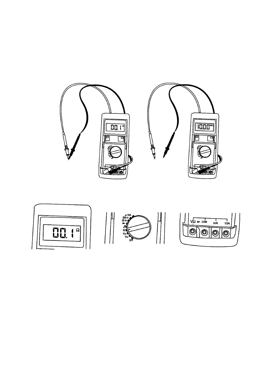
Special cases:
Used as an ohmmeter:
1. When the two wires of the multimeter are in contact, the ohmmeter shows a value of
between 00.0
Ω and 00.5 Ω representing zero resistance If it does not, change the
multimeter battery.
2. When the two wires are separated, the ohmmeter shows by a special display (either
10.00 M
Ω with the 1 which flashes, or ---- ) that there is no connection. This represents
an infinite resistance. (see apparatus instructions)
Note: the ohm values of the coils are given for information and may vary from one
multimeter to another.
Page :
7/17
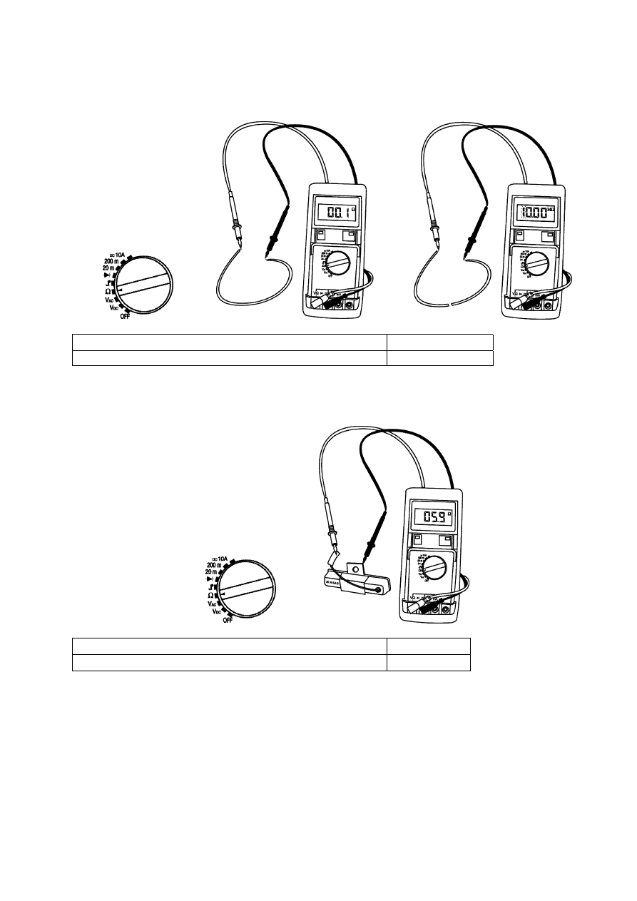
Wires:
Wire intact
00.1
Ω to 00.5 Ω
Wire cut
Infinity
Resistances:
Choke limitation resistance (6.7
Ω 5W)
5.3 to 8
Ω
Lighting resistance (5.9
Ω 30W)
4.7 to 7
Ω

Page :
8/17
Bulbs:
Bulb 12V 1.2W
12
Ω ±25%
Bulb 12V 5W
2.8
Ω ±25%
Bulb 12V 10W
1.4
Ω ±25%
Bulb 12V 15W
0.9
Ω ±25%
Bulb 12V 35W
0.4
Ω ±25%
Bulb blown
Infinity
Saddle control:
Between terminals 1 and 2
note that the probe connections determine the direction of
movement
10
Ω to 40 Ω
Page :
9/17
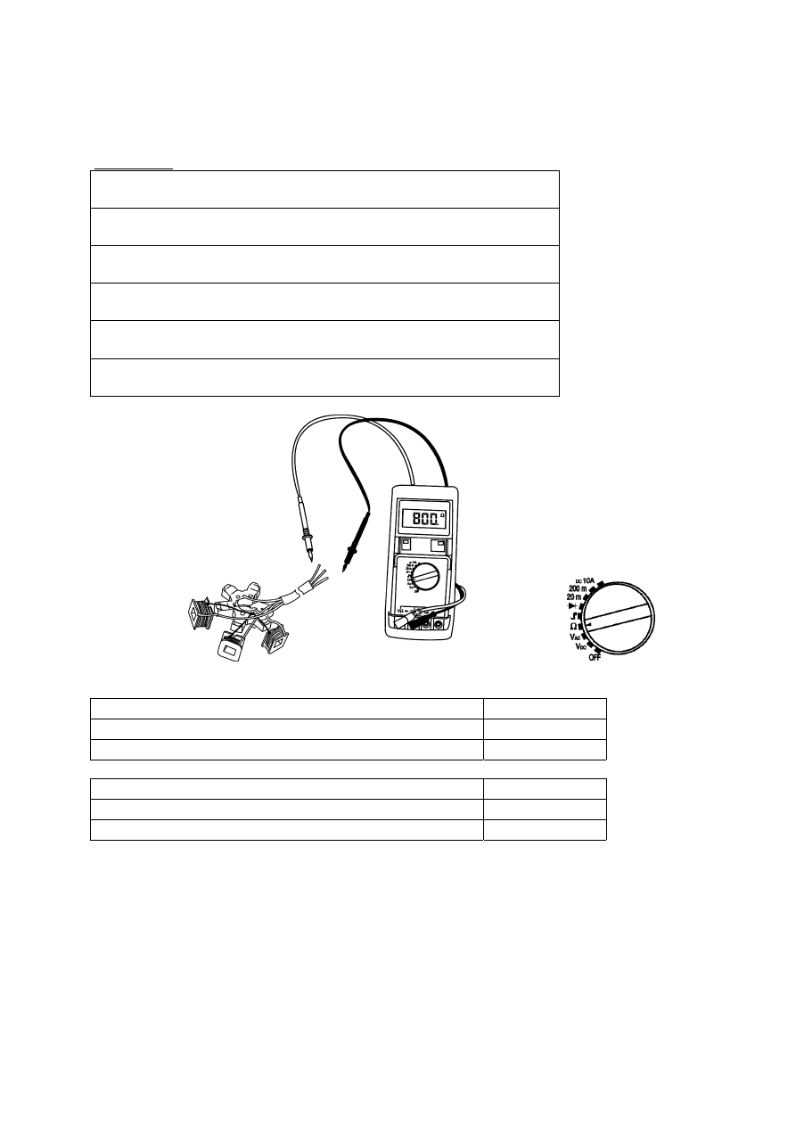
Magneto:
Single-phase:
Reminder:
Moped and Fox
(ignition coils, lighting coils, accessory coils)
Moped 4-pole magneto
(ignition coils, lighting coils, accessory coils)
Fox with battery
(ignition coils, lighting coils, battery charge coils)
CDI ignition
(ignition coils, lighting coils, battery charge coils)
AEC 400 ignition
(ignition coils, lighting coils, battery charge coils)
AC ignition
(lighting coils, battery charge coils)
Mopeds and Fox
Ignition coil between red/black wire and earth
0.800 K
Ω ±20%
Lighting coil between yellow wire and earth
0.9
Ω ±20%
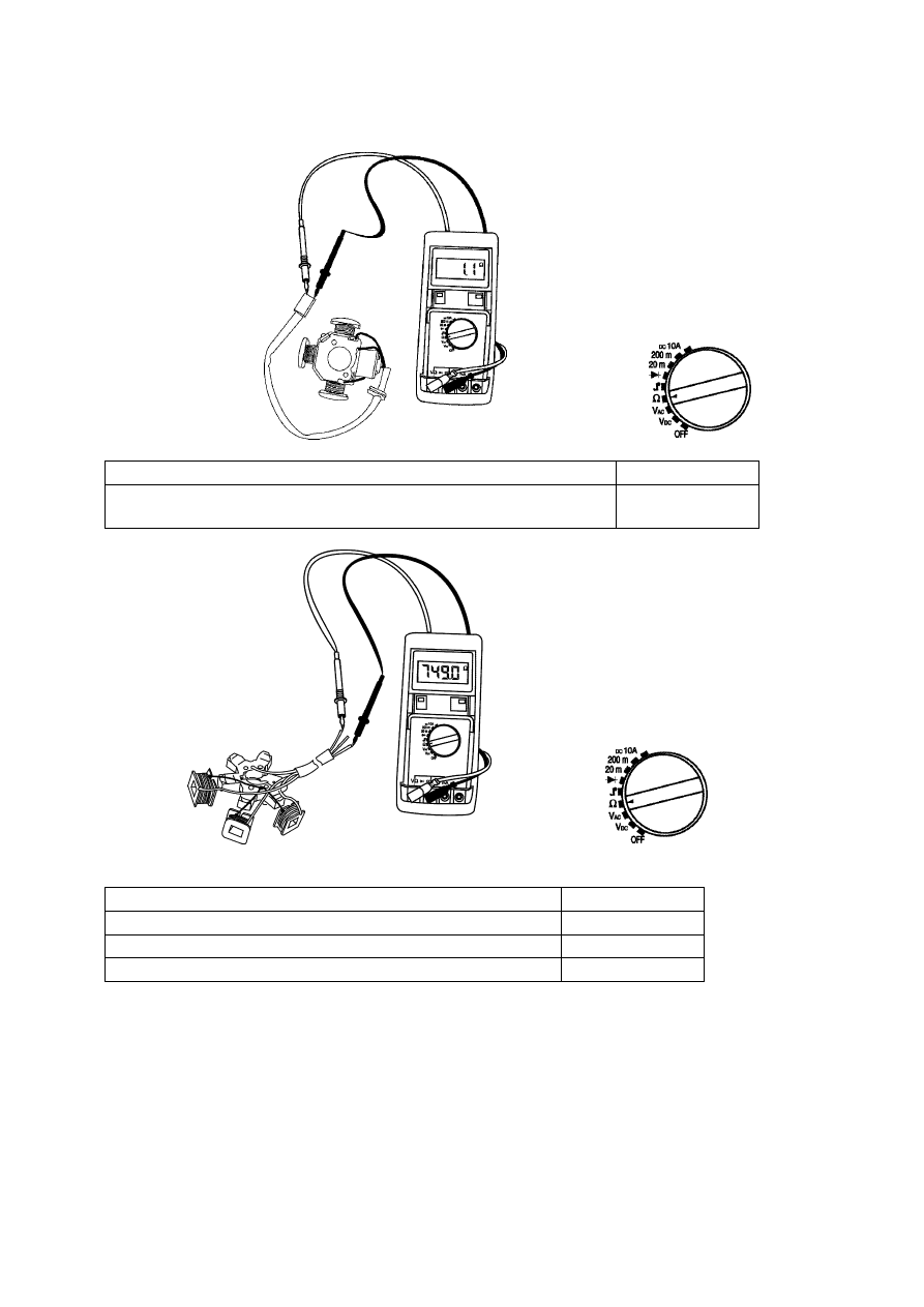
Ignition sensor between yellow/blue wire and earth
106
Ω ±15%
Additional 6W coil
2.1
Ω ±20%
Additional 10W coil
3.5
Ω ±20%
Additional 15W coil
5.25
Ω ±20%
Page :
10/17
4-pole magneto mopeds:
Ignition coil between red/black wire and green wire
0.800 K
Ω ±20%
Lighting and accessories coil between yellow wire and green
wire
1.1
Ω ±20%
Fox with battery
Ignition coil between red/black wire and earth
0.745 K
Ω ±20%
Lighting coil between yellow wire and earth
0.9
Ω ±20%
Battery charge coil between white wire and earth
1.1
Ω ±20%
Ignition sensor between yellow/blue wire and earth
106
Ω ±15%

Page :
11/17
50cc and 100cc scooters with CDI and AEC 400
Ignition coil between red/black wire and earth
0.550 K
Ω ±20%
Lighting coil between yellow wire and earth
0.6
Ω ±20%
Battery charge coil between white wire and earth
0.8
Ω ±20%
Ignition sensor between yellow/blue wire and earth
120
Ω ±15%
50cc and 100c scooter ACI100
Lighting coil between yellow wire and earth
0.6
Ω ±20%
Battery charge coil between white wire and earth
0.8
Ω ±20%
Ignition sensor between yellow/blue wire and earth
120
Ω ±15%

Page :
12/17
Triphase:
125cc and 150cc scooters
Circuit power coil between each of the 3 yellow wires
0.5
Ω ±20%
Ignition sensor between yellow/blue wire and earth
120
Ω ±15%
Page :
13/17
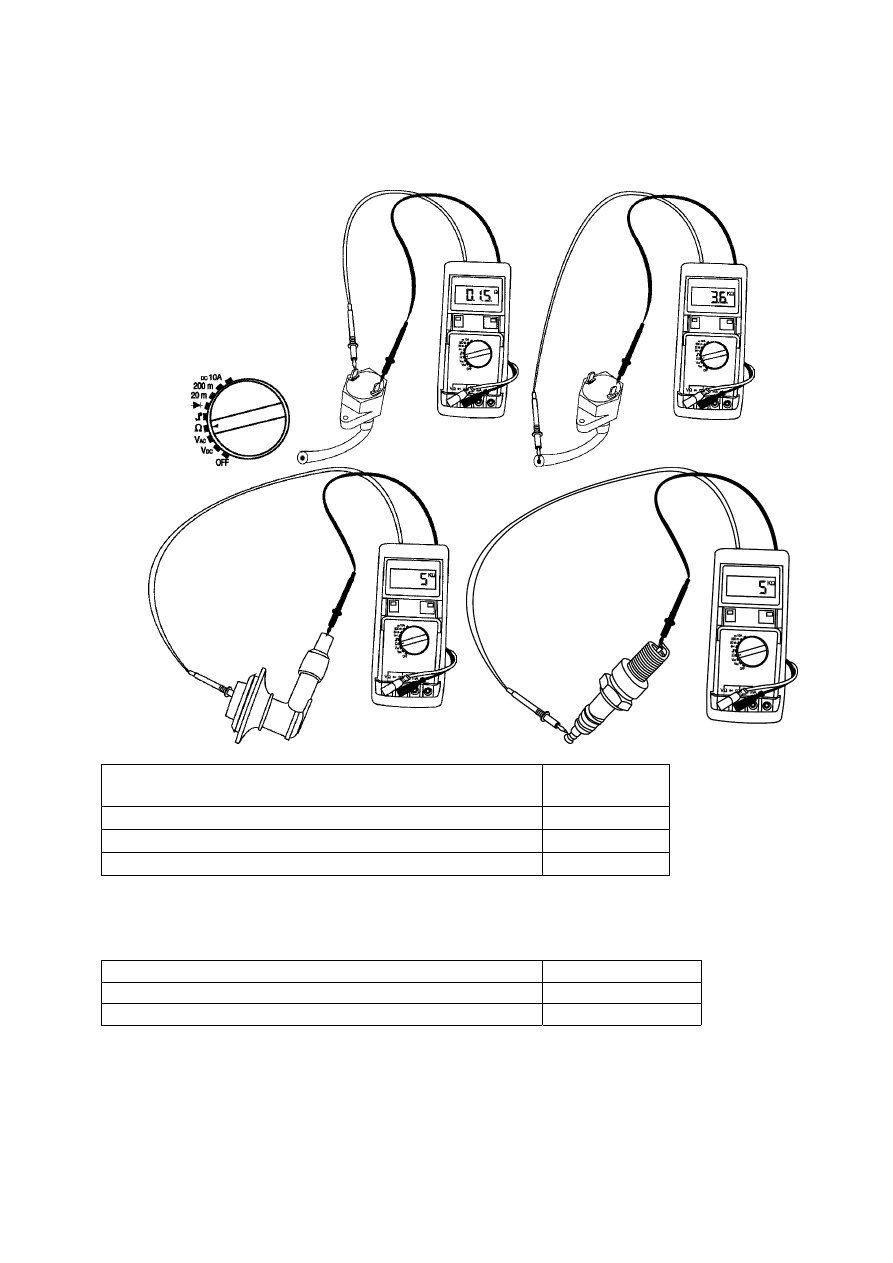
Ignition:
Coil primary between black terminal and green
terminal
0.15 to 0.25
Ω
Coil secondary between green terminal and HV
3.6 to 4.5 K
Ω
Spark plug suppressor
5 K
Ω ±10%
Resistor spark plug
5 K
Ω ±25%
ignition coil:
CDI module
Not testable
AEC 400 module
Not testable
ACI 100 module
Not testable
Page :
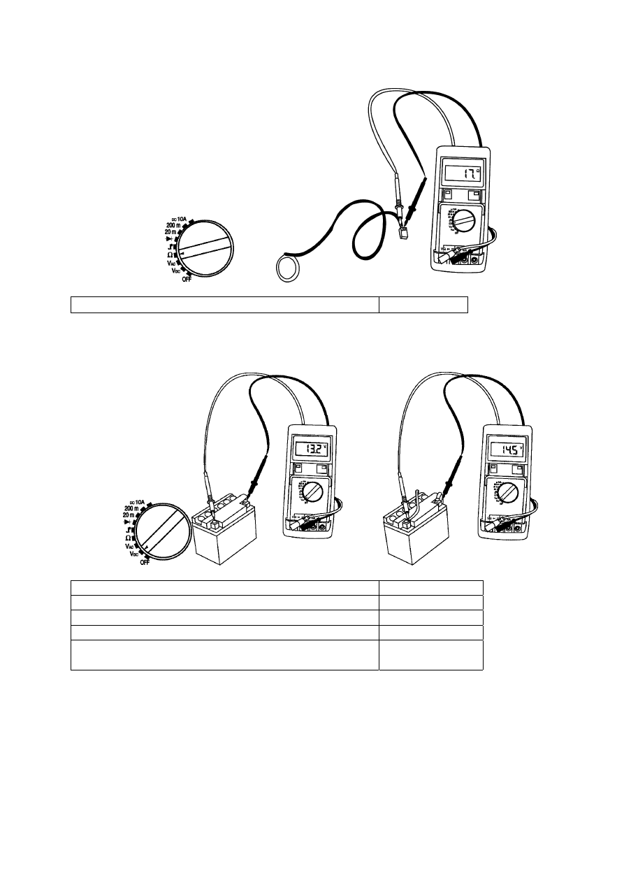
14/17
Transponder antenna
17
Ω ±20%
Battery:
No load, battery charged
12.5 V to 13.5 V
Charging voltage, engine running
14 to 15 V
Battery flat but in working order
12 V
Battery unserviceable
<10 V
Charging current (depending on type of magneto and
battery voltage)
0.1A to 20A
Page :
15/17
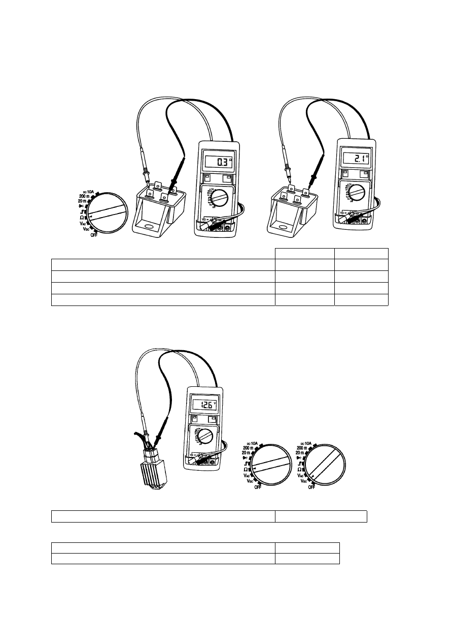
Lighting transformer:
Primary
Secondary
Isolating transformer M (6W)
1.2
Ω ±10%
2.1
Ω ±10%
Isolating transformer H (6W)
1.2
Ω ±10%
2.7
Ω ±10%
Isolating transformer G (15W)
0.4
Ω ±10%
2.8
Ω ±10%
Isolating transformer S (15W)
0.3
Ω ±10%
2.1
Ω ±10%
Voltage regulator:
Engine stopped battery disconnected
Resistance between green wire and battery “-“
00.1
Ω to 00.5 Ω max
Engine running:
Direct current between red and green wires
14 to 15 V
alternative current between yellow and green wires
12.6 to 13.6 V

Page :
16/17
Switches:
Switch closed
00.1
Ω to 00.5 Ω
Switch open
Infinity
Oil level low sensor:
Switch open tank full
Infinity
Switch closed tank empty
00.1
Ω to 00.5 Ω

Page :
17/17
Fuel gauge:
Tank empty
90
Ω to 120 Ω
Tank full
0
Ω to 12 Ω
Starter motor relay:
Large relay (125cc) primary
3.4
Ω
Small diode type electronic relay, primary, ensure
connections made the right way round
65.8
Ω

Page :
18/17
Relay powered, secondary
00.1
Ω to 00.5 Ω

Page :
19/17
Diodes:
Flow direction
Reading under 1
Ω
Opposite direction
Reading over 1
Ω
Red diodes (LEDs)

Page :
20/17
Miscellaneous
At 20°c
At 90°c
50cc coolant type engine temperature sensor ref:736678 2.25 K
Ω ±15% 108 Ω ±15%
125cc engine temperature sensor ref: 740358
1.10 K
Ω ±15% 102 Ω ±15%
Choke heat expandable tip
5
Ω at 20°
Horn
2.5 to 5
Ω
Document Outline
- ELECTRICAL TESTS
Wyszukiwarka
Podobne podstrony:
Mazda 6 (Mazda6) Engine Workshop Manual Mzr Cd (Rf Turbo)(3)
Electrical Safety Student Manual
M6 Engine Workshop Manual L8 LF L3 1 (2)
Mazda 6 (Mazda6) Automatic Transaxle Workshop Manual Supplement JA5AX EL
Test sprawnosci manualnej dla dziecka 5(1), Przedszkole, Pomoce, Testy
Mazda 6 (Mazda6) Engine Workshop Manual Mzr Cd (Rf Turbo)(3)
Electrolux ER 7326 C Manual
Electrolux ER 9096 B Manual
Audi A3 (2004) Workshop Manual
Electrolux ERB 4032 Manual
Electrolux ERN 23500 Manual
Electrolux ERB 2522 Manual
Electrolux ERB 2644 Manual
Electrolux ER 6945 C Manual
Electrolux kuchenka EKK54554OX manual
Electrolux ENB 3840 Manual
Electrolux ERD 2343 Manual
więcej podobnych podstron