Page 1 of 2
©2008 August Home Publishing
All rights reserved.
The biggest challenge to making any router tabletop
is cutting an opening for the insert plate so that it fi ts
perfectly. To answer that challenge when it came to
building the ultimate router table, I used a foolproof
method that doesn’t require any tedious measuring
or layout. Just a few common shop tools. The nice
thing about this method is you can use it to create an
opening for any size or type of plate.
Template & Guide Strips.
This method works
because you use the actual plate as a template for
positioning a set of strips that guide a pattern bit
when you’re cutting the opening. Note: Most pattern
bits will require 1"-thick strips.
NOTE:
GUIDE STRIPS
ARE MADE FROM
HARDBOARD AND
PLYWOOD
!/4"
#/4"
GUIDE STRIP
(3" x 18")
ATTACH
GUIDE
STRIPS WITH
CARPET
TAPE
INSERT PLATE
Step 1
To locate the guide strips, use the
insert plate as a template. Start by
fastening one strip in place with
carpet tape so it’s parallel with one
edge of where the plate is to be
located. After positioning the plate
along this strip so it’s in its final
location, you can “wrap” the plate
with the remaining guide strips.
Step 2
To provide a starting point for the
bit and create relief holes for dust,
drill a 1
1
/
2
"-dia. hole in each corner.
A hole saw works great for this,
but you’ll need to wrap the body
with masking tape to compensate
for the set of the teeth, as you can
see in detail ‘a.’ Once the teeth cut
through the laminate, remove the
tape and complete the hole.
{
For smooth
cutting through
laminate, apply a
spray lubricant to
the hole saw before
drilling the hole.
FIRST:
DRILL STARTER
HOLES WITH TAPE
ON HOLE SAW,
SEE DETAIL 'a'
SECOND:
REMOVE TAPE
AND COMPLETE
THROUGH HOLE, SEE DETAIL 'b'
NOTE:
HOLE SAW
DIAMETER MUST
MATCH INSERT
CORNERS
a.
b.
6-step
Router Plate
Installation
Locate Guide Strips.
After making the guide strips,
you’re ready to locate the opening. To do this, use
double-sided tape to position one of the guide strips
so it’s parallel with one edge of where you’d like the
plate located. Then use the insert plate to locate the
other strips, as shown in Step 1.
Cut Opening.
Once you have the guide strips
located, you’re ready to cut the opening by follow-
ing Steps 2 through 5. With the opening complete, all
that’s left to do to complete the installation is mount
the router to the insert plate. Most insert plates are
predrilled to match your router. If your plate isn’t
drilled, just take a look at Step 6.

Page 2 of 2
©2008 August Home Publishing
All rights reserved.
Step 3
Before routing the lip, set the bit
depth to match the exact thickness
of the insert plate. To do this, mount
the pattern bit in the router. Then
place the insert plate on top of a
guide strip. Set the router on the
plate and lower the bit until it barely
touches the top (see detail). If you
rout too deep, see the margin for a
quick fix. (For access plate, set bit
for
1
/
4
"-deep cut.)
Step 4
At this point, set the bit into the
opening in one of the corners so the
router is resting on the guide strips.
Then use the strips to guide the
bearing on the bit (see detail) as you
rout around the inside of the strips
in a clockwise direction. Note: To
maintain the radius in the corners,
rout only to the edge of starter holes.
(For access plate, make multiple
1
/
4
"-
deep passes through plate.)
Step 5
Once the lip has been routed,
you’re ready to remove the waste.
A jig saw makes quick work of
this. All you need to do is follow
the inside edge of the groove
formed when you routed the lip
(see detail). A little sanding will
clean up the rough edges.
#/8"
Fh
WOODSCREW
ADJUST
WOODSCREW
TO LEVEL
INSERT PLATE
Step 6
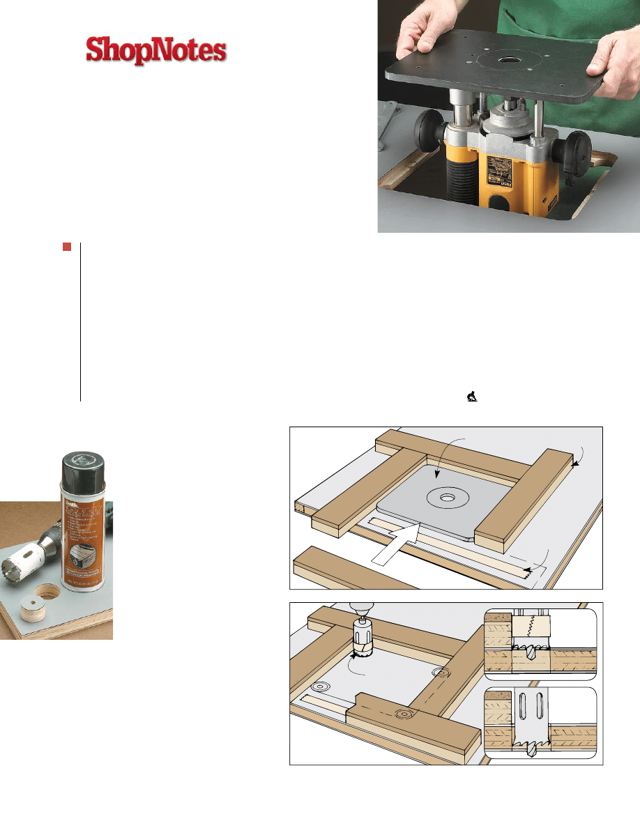
All that’s left is to attach the router
to the mounting plate. This requires
drilling holes for the machine
screws that hold it in place. An
easy way to locate the holes for
the screws is to use the existing
base on your router. (I used carpet
tape to keep the base from shifting,
Fh MACHINE
SCREW
NOTE:
USE ROUTER BASE
TO LOCATE MOUNTING
HOLES, SEE DETAIL
DRILL COUNTERSUNK
HOLES FOR MACHINE
SCREWS
TOP OF
MOUNTING
PLATE
ROUTER
BASE
CARPET
TAPE
NOTE:
CENTER
ROUTER BASE ON
MOUNTING PLATE
S6631D01
INSERT
PLATE
USE INSERT
PLATE TO SET
DEPTH, SEE
DETAIL
CUTAWAY
SHOWN FOR
CLARITY
S6631D01
INSERT
PLATE
USE INSERT
PLATE TO SET
DEPTH, SEE
DETAIL
CUTAWAY
SHOWN FOR
CLARITY
S6631A02
INSERT
PLATE
!/2"
PATTERN
BIT
ADJUST BIT TO
JUST TOUCH TOP OF
ROUTER TABLE
ROUTER
PLATE
ROUT
CLOCKWISE
ALONG GUIDE STRIPS
NOTE:
ROUT LIP FROM ONE
EDGE OF STARTER HOLE
TO OPPOSITE
STARTER HOLE
GUIDE
STRIP
DEPTH OF
CUT EQUALS
THICKNESS
OF INSERT
NOTE:
USE STARTER
HOLES TO REMOVE
WASTE WITH
JIG SAW
LIP
CUT ALONG
INSIDE EDGE
OF GROOVE
WASTE
TABLE
TOP
{
Levelers. If the
lip is routed too
deep, installing
a set of flathead
screws allows you
to raise the insert
plate so it’s flush
with the top of the
router table.
{
Pattern Bit. The
guide bearing at
the top of a pattern
bit makes it easy to
cut a lip or opening
in the center of
a workpiece.
Wyszukiwarka
Podobne podstrony:
install 2015 3 step
Broadband Internet Router Instrukcja obsługi i instalacji
install 15 3 step
Instrukcja obsługi i instalacji routera N150 DGN1000
instalacja debiana
INSTALACJE TRYSKACZOWE I ZRASZACZOWE
Urządzenia i instalacje elektryczne w przestrzeniach zagrożonych wybuchem
Instalacje elektroenergetObl1
Projekt Instalacji deponowanie 2
Instalacje odgromowe
Wybrane elementy automatyki instalacyjnej
instalacje grzewczaet
monter instalacji gazowych 713[07] z2 03 u
8 Instalacja spalin wylotowych id
Installation instructions
ARTICLE SUSPENSION STRUT FRONT REPLACE INSTALL
więcej podobnych podstron