BC857S
Aug-20-2001
1
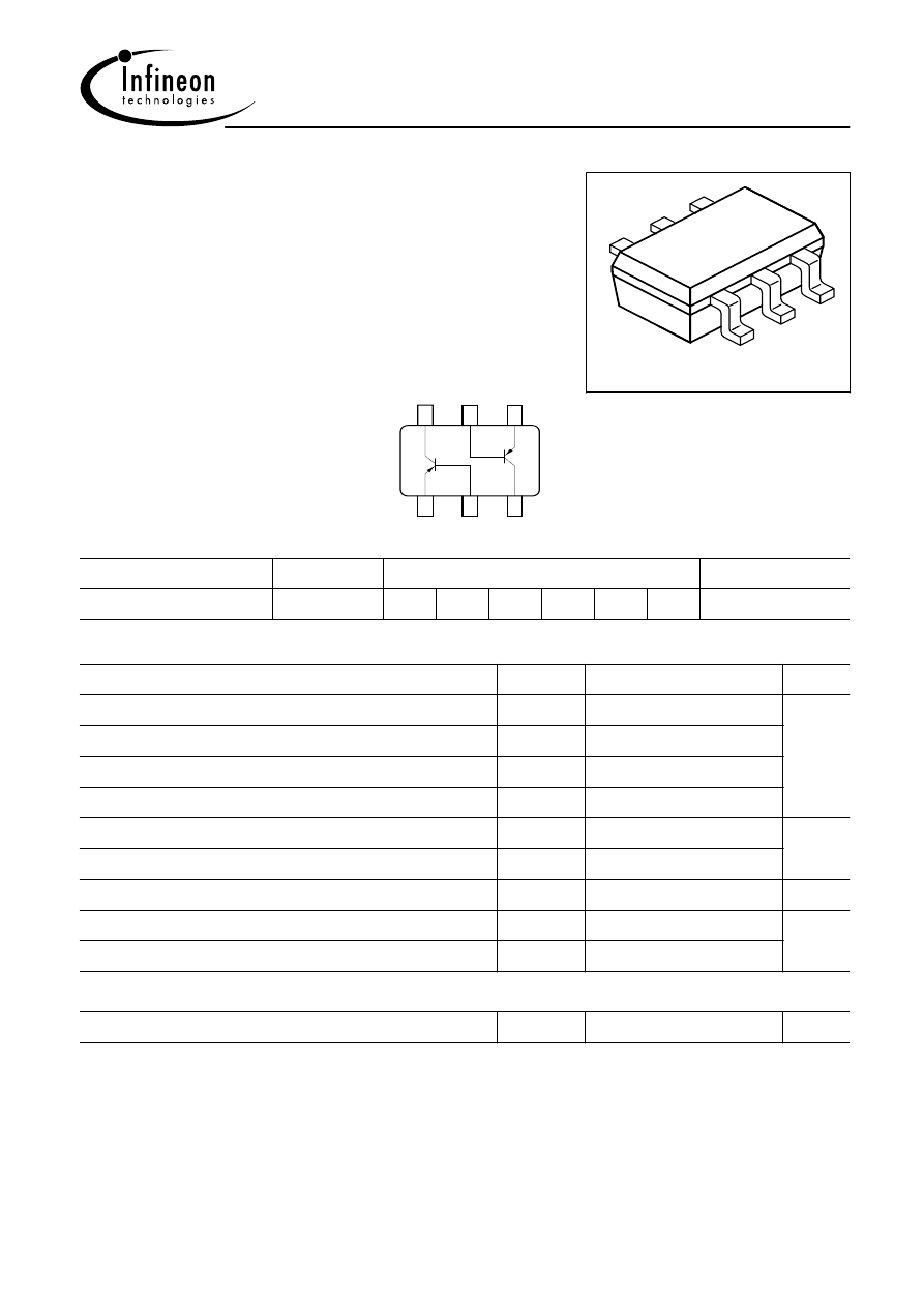
PNP Silicon AF Transistor Array
For AF input stages and driver applications
High current gain
Low collector-emitter saturation voltage
Two ( galvanic) internal isolated Transistors
with good matching in one package
VPS05604
6
3
1
5
4
2
EHA07175
6
5
4
3
2
1
C1
B2
E2
C2
B1
E1
TR1
TR2
Type
Marking
Pin Configuration
Package
BC857S
3Cs
1=E1 2=B1 3=C2 4=E2 5=B2 6=C1 SOT363
Maximum Ratings
Parameter
Symbol
Value
Unit
V
CEO
45
Collector-emitter voltage
V
Collector-base voltage
50
V
CBO
Collector-emitter voltage
V
CES
50
Emitter-base voltage
5
V
EBO
DC collector current
I
C
100
mA
Peak collector current
200
I
CM
250
Total power dissipation
,
T
S
= 115 °C
P
tot
mW
Junction temperature
T
j
150
°C
Storage temperature
T
stg
-65 ... 150
Thermal Resistance
Junction - soldering point
1)
R
thJS
140
K/W
1For calculation of R
thJA
please refer to Application Note Thermal Resistance

BC857S
Aug-20-2001
2
Electrical Characteristics at T
A
=25°C, unless otherwise specified
Parameter
Symbol
Unit
Values
min.
max.
typ.
DC Characteristics per Transistor
Collector-emitter breakdown voltage
I
C
= 10 mA,
I
B
= 0
V
-
V
(BR)CEO
-
45
Collector-base breakdown voltage
I
C
= 10 µA,
I
B
= 0
-
-
V
(BR)CBO
50
Collector-emitter breakdown voltage
I
C
= 10 µA,
V
BE
= 0
-
-
50
V
(BR)CES
5
V
(BR)EBO
Emitter-base breakdown voltage
I
E
= 10 µA,
I
C
= 0
-
-
Collector cutoff current
V
CB
= 30 V,
I
E
= 0
I
CBO
-
-
15
nA
Collector cutoff current
V
CB
= 30 V,
I
E
= 0 ,
T
A
= 150 °C
I
CBO
-
-
5
µA
DC current gain 1)
I
C
= 10 µA,
V
CE
= 5 V
I
C
= 2 mA,
V
CE
= 5 V
h
FE
-
200
250
290
-
-
630
Collector-emitter saturation voltage1)
I
C
= 10 mA,
I
B
= 0.5 mA
I
C
= 100 mA,
I
B
= 5 mA
mV
300
650
V
CEsat
75
250
-
-
Base-emitter saturation voltage 1)
I
C
= 10 mA,
I
B
= 0.5 mA
I
C
= 100 mA,
I
B
= 5 mA
V
BEsat
-
-
700
850
-
-
Base-emitter voltage 1)
I
C
= 2 mA,
V
CE
= 5 V
I
C
= 10 mA,
V
CE
= 5 V
V
BE(ON)
600
-
650
-
750
820
V
1) Pulse test: t < 300
s; D < 2%

BC857S
Aug-20-2001
3
Electrical Characteristics
at T
A
= 25 °C, unless otherwise specified.
Parameter
Symbol
Values
Unit
min.
typ.
max.
AC characteristics
Transition frequency
I
C
= 20 mA,
V
CE
= 5 V,
f
= 100 MHz
f
T
-
250
-
MHz
Collector-base capacitance
V
CB
= 10 V,
f
= 1 MHz
C
cb
-
3
-
pF
Emitter-base capacitance
V
EB
= 0.5 V,
f
= 1 MHz
C
eb
-
10
-
Short-circuit input impedance
I
C
= 2 mA,
V
CE
= 5 V,
f
= 1 kHz
h
11e
-
4.5
-
k
Open-circuit reverse voltage transf.ratio
I
C
= 2 mA,
V
CE
= 5 V,
f
= 1 kHz
h
12e
-
2
-
10
-4
Short-circuit forward current transf.ratio
I
C
= 2 mA,
V
CE
= 5 V,
f
= 1 kHz
h
21e
-
330
-
-
Open-circuit output admittance
I
C
= 2 mA,
V
CE
= 5 V,
f
= 1 kHz
h
22e
-
30
-
S
Noise figure
I
C
= 200 µA,
V
CE
= 5 V,
R
S
= 2
k
,
f
= 1 kHz,
f
= 200
Hz
F
-
-
10
dB
BC857S
Aug-20-2001
4
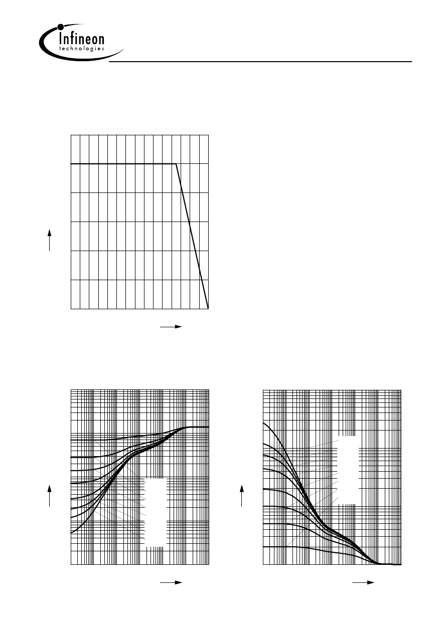
Total power dissipation P
tot
= f (T
S
)
0
20
40
60
80
100
120 °C
150
T
S
0
50
100
150
200
mW
300
P
tot
Permissible Pulse Load
P
totmax
/ P
totDC
= f (t
p
)
10
-6
10
-5
10
-4
10
-3
10
-2
10
0
s
t
p
0
10
1
10
2
10
3
10
-
P
totmax
/ P
totDC
D = 0
0.005
0.01
0.02
0.05
0.1
0.2
0.5
Permissible Pulse Load R
thJS
= f (t
p
)
10
-6
10
-5
10
-4
10
-3
10
-2
10
0
s
t
p
-1
10
0
10
1
10
2
10
3
10
K/W
R
thJS
0.5
0.2
0.1
0.05
0.02
0.01
0.005
D = 0
BC857S
Aug-20-2001
5
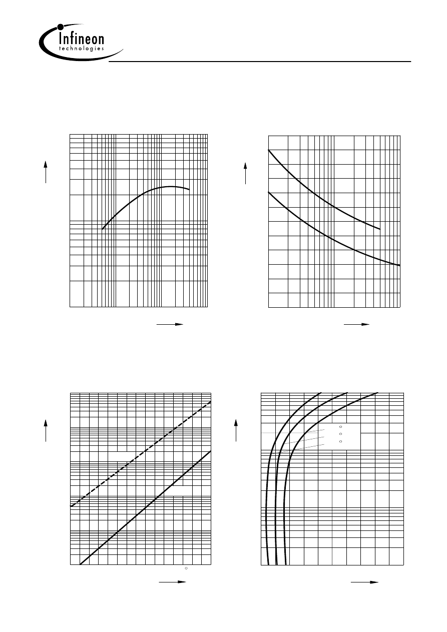
Transition frequency
f
T
= f (I
C
)
V
CE
= 5V
10
10
10
10
EHP00378
f
mA
MHz
-1
0
1
2
5
T
3
10
10
2
1
10
5
5
5
C
Ι
Collector-base capacitance C
CB
= f (V
CBO
)
Emitter-base capacitance
C
EB
= f (V
EBO
)
0
4
10
5
10
10
EHP00361
V
CB0
C
EB0
V
6
2
EB0
V
EB
C
8
10
pF
12
CB0
C
-1
0
1
C
CB
(
(
)
BC 846...850
)
Collector cutoff current
I
CBO
= f (T
A
)
V
CB
= 30V
10
0
50
100
150
EHP00381
T
A
5
10
10
nA
10
Ι
CB0
5
5
5
10
10
4
3
2
1
0
-1
max
typ
C
Collector-emitter saturation voltage
I
C
= f (V
CEsat
), h
FE
= 20
10
0
EHP00380
V
CEsat
10
mA
10
10
2
1
0
-1
5
5
V
0.3
0.5
100
25
-50
0.1
0.2
0.4
C
Ι
C
C
C
BC857S
Aug-20-2001
6
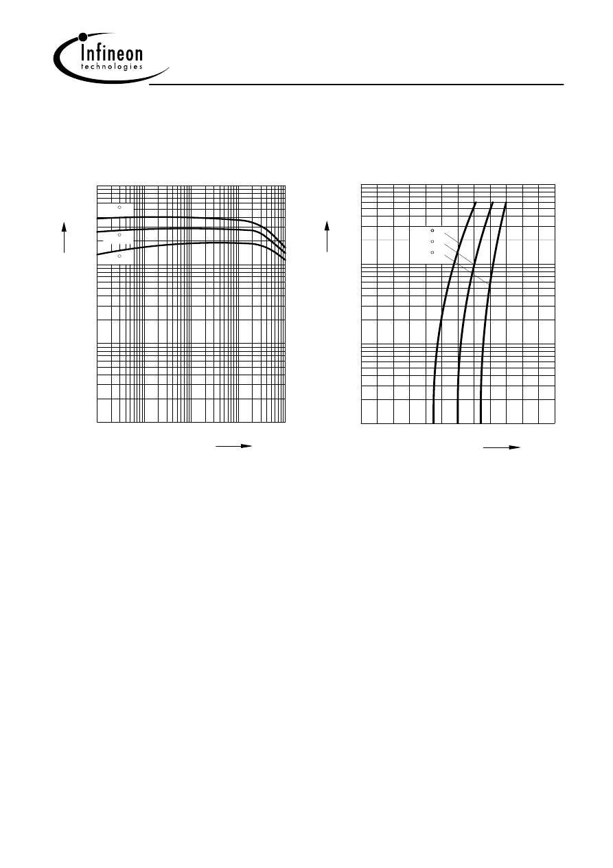
DC current gain
h
FE
= f (I
C
)
V
CE
= 5V
10
10
10
10
EHP00382
h
mA
-2
-1
1
2
FE
3
10
10
2
0
10
5
5
10
1
0
10
5
5
5
5
100
25
-50
C
Ι
C
C
C
Base-emitter saturation voltage
I
C
= f (V
BEsat
), h
FE
= 20
0
10
EHP00379
BEsat
V
0.6
V
1.2
-1
10
0
10
1
2
10
5
5
Ι
C
mA
0.2
0.4
0.8
C
25
C
100 C
-50C
Wyszukiwarka
Podobne podstrony:
MMBT2222A, SMBT2222A (Infineon)
MMBT2907A, SMBT2907A (Infineon)
MMBT3904, SMBT3904 (Infineon)
TCA105 Infineon elenota pl
Infineon Plans
BC807, BC808 (Infineon)
BSS92 (Infineon)
MMBT3906, SMBT3906 (Infineon)
BSS88 (Infineon)
więcej podobnych podstron