Another internet tool by:
Build Your Own
Page 1 of 9
Teach...build...learn...renewable energy!
Wind Turbine
A Renewable Energy Project Kit
The Pembina Institute
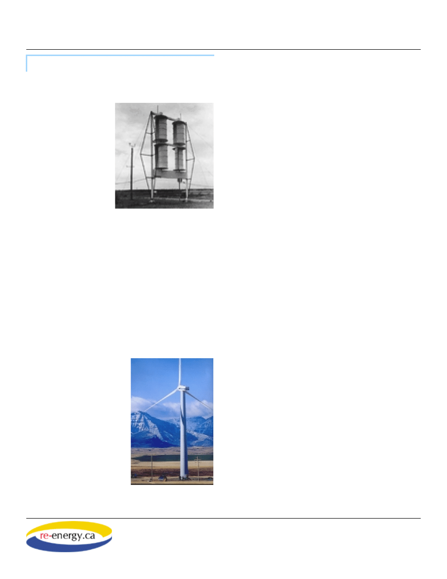
The Savonius Wind Turbine
These plans are for the construction of a machine
called a Savonius wind
turbine. Wind turbines
come in two general
types, those whose
main turning shaft is
horizontal and points
into the wind, and
those with a vertical
shaft that points up.
The Savonius is an
example of the vertical
axis type. It consists of
two simple scoops that
catch the wind and cause the shaft to turn.
This type of turbine is simple to build, but is not
nearly as effi cient as a well-designed horizontal axis
turbine. The Savonius turbine relies solely on drag
to produce the force that turns their shaft. One side
of the turbine catches the moving air more than the
other, causing the turbine to spin. This design does
not allow the turbine to spin faster than the oncom-
ing wind, which makes them a poor choice in areas
where winds are light.
Horizontal axis turbines are
by far the most common
kind of wind turbine. They
can be seen at several
places across Canada and
the United States. They
are also becoming common
in Europe and many other
countries around the world.
These turbines feature
wing-like blades that gen-
erate aerodynamic lift as
the wind blows past them,
causing the central shaft to
turn. To operate at peak effi -
ciency, this type of turbine must always face directly
into the wind. Many horizontal turbines have a large
wind vane that acts like a sail, helping them to stay
pointed in the right direction.
Making electricity
We are surrounded by hundreds of appliances that
use electricity to do work. But what is electricity?
Basically, electricity is a fl ow of electrons in a metal
wire, or some other conductor. Electrons are tiny
particles found inside atoms, one of the basic build-
ing blocks of all matter. We call the fl ow of electrons
through any conductor a “current of electricity.”
Each electron carries a tiny negative charge. When
they move through a conductor, they produce an
invisible fi eld of magnetic force, similar to that found
around a magnet. The strength of that fi eld depends
on how many electrons are in motion. You can con-
centrate this fi eld by winding the wire in which the
electrons move into a tight coil with many turns.
This causes many more electrons to be in motion in
a small space, resulting in a stronger fi eld. If you
then place a piece of iron in the middle of the coil,
the electromagnetic fi eld will turn the iron into a
powerful magnet.
While it is true that electrons moving through a con-
ductor produce a magnetic fi eld, the reverse is also
true. You can make electrons move in a wire by
“pushing” them with a moving magnet. This is in fact
how an electrical generator works. Electrical gen-
erators usually contain powerful magnets that rotate
very close to dense coils of insulated wire. The coils
develop a fl ow of electrons that becomes an electrical
current when the generator is connected to an electric
circuit.
You will be building an electrical generator as part of
this project. It uses moving magnets to create a cur-
rent of electricity in coils of wire. This generator is
technically called an alternator because the electrons
move back and forth in the wire, rather than fl owing
in just one direction as they do from a battery. A
A Savonius wind turbine.
A horizontal axis turbine.
Courtesy Vision Quest
Wind Electric Inc.
Background
Another internet tool by:
Build Your Own
Page 2 of 9
Teach...build...learn...renewable energy!
Wind Turbine
A Renewable Energy Project Kit
The Pembina Institute
meter connected to the wire would show that the
charge of the wire switches or alternates between
positive and negative as the electrons change direc-
tions. Such an electrical current is called alternating
current or AC. Household electrical current is alter-
nating current. Appliances have to be specially
designed to use it. The other type of current is
called direct current, because the electrons move
in one direction only. Most battery-powered appli-
ances such as calculators and portable CD players
use direct current.
Safety Precautions
Utility knives and scissors can be dangerous! Use
caution when cutting materials using them. The
blades of most utility knives can be extended and
locked in place. Extend the blades only far enough
to cut all the way through the material, no farther.
Be sure they are locked in position while cutting.
For a safe and easy cutting make sure the blades
of your utility knives are always sharp (ask your
teacher for assistance in breaking off dull blades)
Hot glue guns can cause serious burns, as can the
glue if it comes in contact with your skin.
The magnets you will be using can cause serious
damage to computers or other electronic devices.
Be sure to keep them away from credit cards, com-
puter disks, audio tapes, or any other materials on
which information is stored magnetically.
Important note: Please read and follow these instruc-
tions carefully, step by step! Have one member of
your group read each step aloud to be sure the
instructions are clearly understood. Do not proceed
until each step has been completed.
A. Prepare the Templates
Included with these instructions are three paper tem-
plates, labeled “Base, Frame, and Rotor”. These need
to be glued down on either cardboard or wood before
you can proceed with the assembly of your turbine.
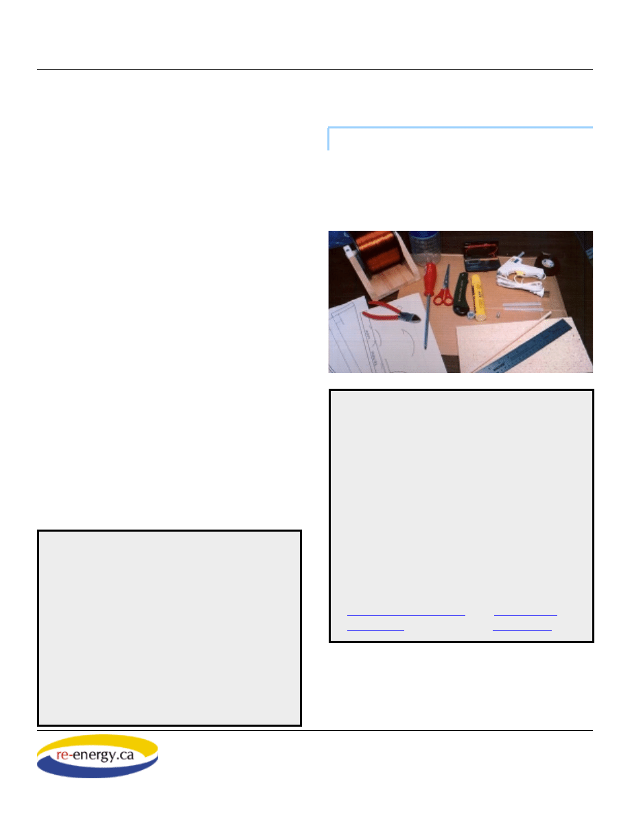
Materials
• 1.5-litre plastic water bottle
• Large piece of corrugated cardboard (approx. 60 cm by
40 cm, cut with corrugations running its length)
• Wooden base (plywood, particle board, or solid wood,
approx. 14cm by 30 cm, at least 15mm thick)
• 1 wood screw (#8, 3/4” Robertson)
• white glue
• nail or awl
• Wooden dowel, 30 cm by 6 mm (1/4”)
• Magnet wire (100m, 24 gauge enamel coated)
• Rectangle of corrugated cardboard, 4cm by 16 cm cut
with corrugations running perpendicular to the long axis
of the rectangle
• Paper Templates: please download the following
templates separately and print according to printing
instructions.
Printing Instructions (37K) Frame (179K)
The Pembina Institute
Tools
• Scissors
• Utility knife
• Hot glue gun and glue sticks
• Metal or plastic ruler
• Robertson screwdriver, no. 2
• Pencil
• Electrical tape
• Digital voltmeter with probes equipped with alligator
clips
• Pencil sharpener
• Sand paper or emery cloth
• 4 rare earth magnets
• push pin
Build It!
Another internet tool by:
Build Your Own
Page 3 of 9
Teach...build...learn...renewable energy!
Wind Turbine
A Renewable Energy Project Kit
The Pembina Institute
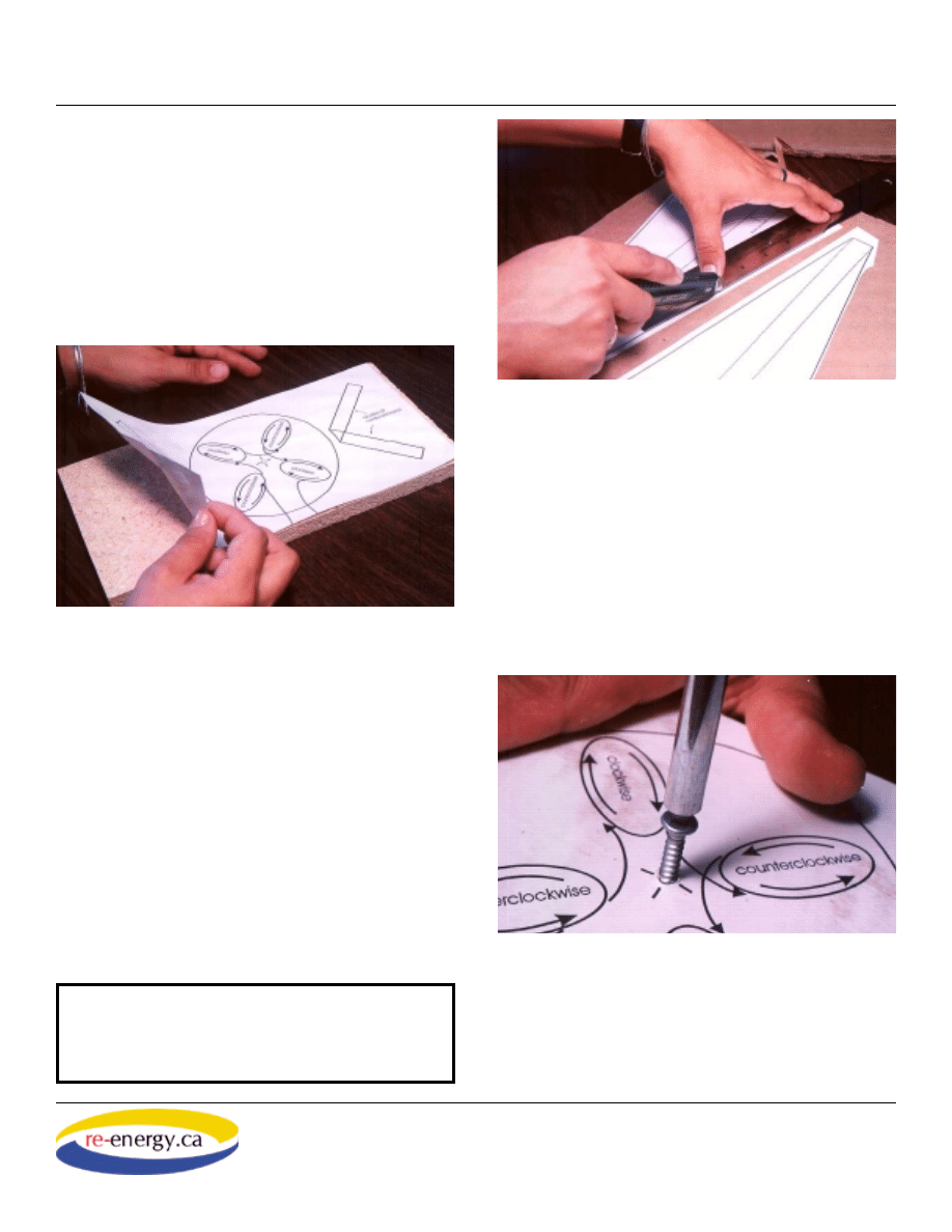
1. Cut out the “Base Template” to fi t the rectangular
base board using your scissors.
2. Apply a very thin, even layer of white glue to
the back of the paper “Base template”, being sure to
cover the entire back surface of the template. Apply
the template to the wooden board, and set it aside
to dry.
3. Cut out the 3 pieces of the frame template and the
parts from the “Rotor templates” sheet.
4. Apply a thin layer of white glue to the back of
the paper “Frame templates” and “Rotor templates”,
carefully place on cardboard, and let dry. As you glue
down the frame templates, be sure their long axis is
parallel to the corrugations in the cardboard.
B. Assemble the Frame
The frame of your turbine consists of 4 parts: the top
and two side pieces made of corrugated cardboard,
and the base, which is from a short piece of plywood
or 2 by 6 lumber.
1. Cut out the sides and tops of the frame pieces
using the utility knife. The metal ruler can be used to
help make the cuts straight. You may use the bottom
surface of the board as a cutting board to prevent
damage to the tabletop.
2. Using a nail or awl, make a small hole in the
center of the wooden base. Turn the screw into the
wood so that it projects above the board by about
4mm.
3. Set the blade of the utility knife so that it
projects about 2 mm from the handle, and make shal-
low cuts along the dotted lines on the frame parts
where shown. The cuts allow the cardboard to bend
smoothly along straight lines.
The Pembina Institute
The Pembina Institute
The Pembina Institute
CAUTION!
The utility knife is sharp, and can
cause serious cuts. Extend the blade only as far as
needed to cut through the cardboard, and lock the
blade in place!
Another internet tool by:
Build Your Own
Page 4 of 9
Teach...build...learn...renewable energy!
Wind Turbine
A Renewable Energy Project Kit
The Pembina Institute
4. Gently bend the frame
parts as shown.
5. Glue the uprights to
the board at the locations
shown on the base tem-
plate using hot glue.
6. Score and bend the
top frame support so that it
spans the distance between
the two side pieces. The
pinhole should be centered directly over the screw.
Use a drop of hot glue on each side support to hold
the top support in place.
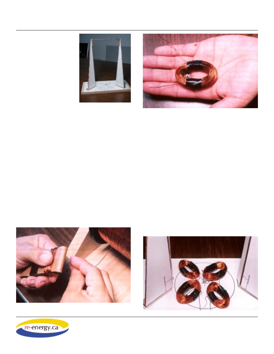
C. Assemble and Mount the Coils
1. Make a winding jig by folding a small piece
of corrugated cardboard in half and securing with
tape. The jig should measure 3cm by 8 cm when
completed.
2. Cut 8 short (4 cm) strips of electrical tape, and
set them aside.
3. Leaving a wire lead of about 5 cm, start winding
the fi rst coil on the jig. Form a compact coil with 200
turns of wire, ending with another 5 cm lead. Cut the
wire with wire cutters or scissors.
4. Carefully slip the coil off the jig, and secure it on
each side using the two strips of electrical tape.
5. Using a piece of sandpaper, remove the enamel
insulation from the ends of each lead, exposing about
1 cm of bare wire.
6. Repeat steps 1 through 5 to make three more
coils.
7. Loosely position all 4 coils on the base, according
to the “clockwise” / “counterclockwise” markings
on the base template. It helps to trace the path an
electron might take through the coils, starting at one
end. Ensure each coil is arranged so that an electron
moving through the wire follows each coil, alternat-
ing between clockwise or counterclockwise direc-
tions.
The Pembina Institute
The Pembina Institute
The Pembina Institute
The Pembina Institute
Another internet tool by:
Build Your Own
Page 5 of 9
Teach...build...learn...renewable energy!
Wind Turbine
A Renewable Energy Project Kit
The Pembina Institute
8. When you are sure you have oriented the coils
correctly, connect the ends of the wire coils by twist-
ing the bared ends together tightly.
9. Check your connections: Set a multi-meter for
measuring electrical resistance (Ohms). Connect the
probes to the two free ends of the wires from the
coils. A good connection should yield a resistance
reading of 7 to 10 Ohms (a lower reading indicates
an even better connection). A large reading means
that you have a poor connection between two or
more of your coils. You may need to check each
connection individually, and re-sand the wires before
reconnecting to ensure all the insulation has been
removed.
10. Once you are confi dent the coils are properly
positioned and connected, glue them down on the
stator disk. Use a blob of hot glue under each to
ensure they will not shift.
D. The Rotor
The rotor is a rotating disk equipped with magnets.
This disk will spin near the coils to induce an electri-
cal current.
1. Use a nail or an awl to punch a hole through the
center of the cardboard rotor disk. Be careful not to
bend or deform the cardboard while you are doing
this.
2. Carefully separate the magnets (some magnets
may very strong and may require a ruler to pry them
apart.)
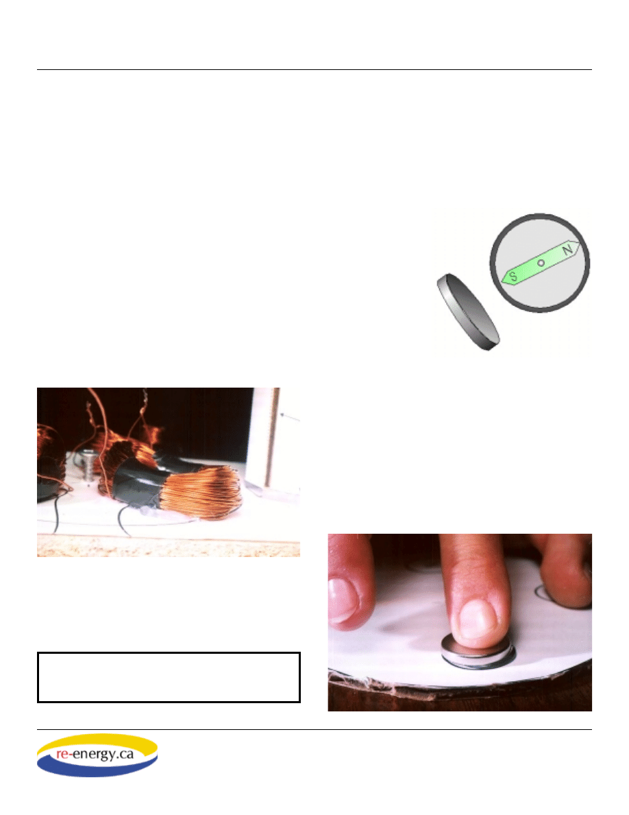
3. Identify the
north pole on each
magnet, and mark
it with a felt pen.
Some magnets
may have a mark
(a red dot or some
other mark) to
identify which
surface is the
north pole. If there
is no mark, you
may need to use a
magnetic compass to help identify the poles.
4. Put a generous blob of hot glue on the center of
the fi rst circle and press a magnet down fi rmly onto
the blob. Be sure mount the magnets so that their
poles alternate, as shown on the template.
The Pembina Institute
Using a compass to identify the
pole of a magnet.
The Pembina Institute
The Pembina Institute
CAUTION!
In this section you will be using the
hot glue gun. Be careful not to get the hot glue on
your skin--it burns!
Another internet tool by:
Build Your Own
Page 6 of 9
Teach...build...learn...renewable energy!
Wind Turbine
A Renewable Energy Project Kit
The Pembina Institute
5. Do not mount the next magnet until the glue
holding the fi rst one is cooled properly.
E. The Turbine
1. Using a nail or awl, punch a hole in the middle of
each turbine end piece as marked (this is where your
wooden dowel will slide through).
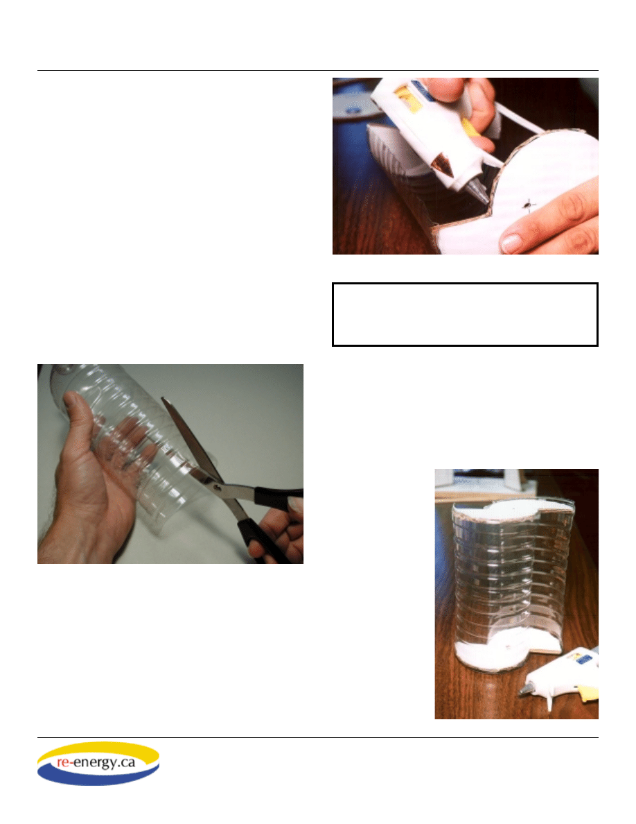
2. Using the utility knife or scissors carefully cut the
top and bottom off the plastic pop or water bottle, to
make a cylinder with open ends.
3. With the scissors, cut the plastic cylinder length-
wise into two equal halves. These bottles usually
have faint lines on their surfaces that show the edges
of the mould used to make them. These lines make
an excellent guide for cutting the bottle into two
perfectly equal halves.
4. Check the fi t of the end pieces of the turbine with
the plastic cylinder halves. You may need to trim
either the plastic or the cardboard to get a better fi t.
5. Apply a “bead” of hot glue onto the curved edge
of one of the cardboard end pieces. Quickly position
one of the cylinder halves onto this edge, holding it
steady for about 20 seconds while the glue cools and
hardens.
6. Apply glue to the second end piece, and position it
onto the cylinder you glued in step 5.
7. Use the glue gun to apply hot glue to the remain-
ing halves of each end piece, then add the second
cylinder. This operation may take two people, one
to hold the par-
tially assembled
turbine, the other
to position the
plastic half-cylin-
der onto the hot-
glued end piece.
8. Use a pencil
sharpener to make
a point on one
end of the wooden
dowel. Round off
the point using the
sandpaper.
The Pembina Institute
The Pembina Institute
The Pembina Institute
CAUTION!
Be sure to apply the glue to the card-
board and not the plastic! The hot glue will deform
the plastic if applied directly, and make it diffi cult
to assemble the turbine.
Another internet tool by:
Build Your Own
Page 7 of 9
Teach...build...learn...renewable energy!
Wind Turbine
A Renewable Energy Project Kit
The Pembina Institute
9. Check the fi t of the turbine shaft in the frame by
placing its sharpened point in the center screw and
standing it inside the frame. The top of the dowel
should just fi t under the top frame support. Cut the
doweling as necessary using the utility knife.
10. Insert a push pin through the pinhole location
and into the top of the dowel. The dowel should turn
easily and freely inside the frame.
11. Remove the push pin, and remove the dowel
from the frame. Carefully push the dowel through the
nail holes in the end pieces of the turbine. Slide the
turbine on the dowel so that about 3 cm of the dowel
sticks out above the turbine end pieces.
12. Recheck the turbine vanes and shaft for fi t inside
the frame. The turbine vanes should spin easily with-
out hitting the sides of the frame. Add a bead of hot
glue to the top and bottom of the end pieces where
the dowel comes through to fi x the turbine vanes to
the shaft. You are now ready for the fi nal assembly
and testing of your wind turbine!
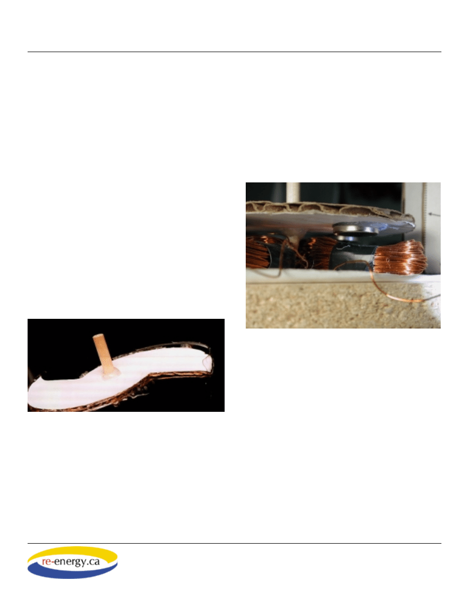
F. Final Assembly
The object of this stage is to position the magnet-
equipped disk so it spins smoothly, and as close to
the coils as possible. The closer they are to the coils,
the more electricity they will make.
1. Carefully push the pointed end of the turbine shaft
through the top of the rotor disk at its exact center.
The magnets should be facing down. Avoid bending
the cardboard. Slide the disk so that about 2.5 cm of
the dowel projects from the cardboard.
2. Check the position of the rotor disk on the dowel
by placing it inside the frame and re-inserting the
push pin. The magnets should turn freely without
striking the coils or snagging the wire between them.
If necessary, press the wires down and out of the
way, and press the coils in to a fl atter shape to ensure
they do not interfere with the magnets.
3. The disk should spin smoothly without wobbling.
If the disk wobbles, you will have to adjust the angle
a bit. Make small adjustments to the height and angle
of the disk so that it spins smoothly, and as close to
the magnets as possible.
4. If you are satisfi ed with the position of the disk,
add a bead of hot glue around the dowel where it
comes through the top surface of the cardboard disk.
You can do this without removing it from the frame.
Recheck the rotor disk by spinning it. You can make
small adjustments to the disk’s position and angle as
the glue sets.
5. After the hot glue cools, remove the rotor and
turbine assembly from the frame. Reinforce the disk
The Pembina Institute
The magnets should pass as close to the coils
as possible.
The Pembina Institute
Another internet tool by:
Build Your Own
Page 8 of 9
Teach...build...learn...renewable energy!
Wind Turbine
A Renewable Energy Project Kit
The Pembina Institute
with an additional bead of hot glue applied to the
shaft where it projects from the underside of the disk.
6. Reassemble the turbine and check again to make
sure the clearance between the coils and magnets is
correct. You can make further adjustments by turning
the center screw out or in depending on whether you
want to increase or decrease the clearance between
the coils and the magnets.
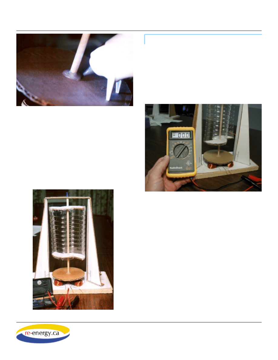
1. Set the selector on the digital volt meter to read
Volts AC. At this setting, the meter will detect the
number of volts of alternating current your turbine
produces.
2. Attach the test clips on the volt meter to the wire
leads on your turbine.
3. Blow on your turbine to cause it to spin. Have
a partner watch the readings on the display of the
meter. Record your results. A well-assembled wind
turbine should be able to produce between 1 and
two volts by blowing on it. A more consistent way
to test your turbine is to use a stream of air from
an appliance such as a blow dryer (set for COOL)
or a vacuum cleaner with the hose plugged into the
discharge end. Measure the voltage of your turbine
and compare with others.
4. You may make small modifi cations to improve
the effi ciency of your turbine. Look for sources of
friction that might slow down its rotation, or fi nd
ways to bring the coils closer to the spinning mag-
nets.
The Pembina Institute
The completed vertical axis turbine.
The Pembina Institute
The Pembina Institute
Test It!

Another internet tool by:
Build Your Own
Page 9 of 9
Teach...build...learn...renewable energy!
Wind Turbine
A Renewable Energy Project Kit
The Pembina Institute
Acknowledgements
The design of this turbine is based closely
on the ingenious “Pico-turbine”, published as a
free download from
PicoTurbine.com is one of the best sources of ideas
and resources for renewable energy education in
North America.
Sources
Magnets: Lee Valley Tools Ltd. Phone 1-800-
267-8767. Part #99K32.11
Wire: In Edmonton, Electronic Connections Ltd.,
Ph. 780-469-7222. Ask for 24-gauge enameled
magnet wire. Sold by weight.
Questions
1. What changes to this design could you
make to improve the effi ciency of this turbine?
2. What advantages does the vertical axis
turbine have over conventional horizontal axis
turbines?
3. What limits or disadvantages does this
design have?
4. Why must the coils be positioned in a
clockwise / counterclockwise manner?
5. What is the difference between alternating
current (AC) and direct current (DC)?
Notes:
Wyszukiwarka
Podobne podstrony:
0 Wind Turbine Construction Manual Piggott 2001
Ebook Wind Power Savonius Generator Plans Pico Turbine
eBook Wind Power Savonius Rotor Construction by Jozef A Kozlowski WInd Power
eBook Wind Power Savonius Rotor design and function a new look Mother Earth News
Ebook Wind Power Savonius Generator Wind Energy For Earth Keepers Savonius Wind Mill
[2006] Application of Magnetic Energy Recovery Switch (MERS) to Improve Output Power of Wind Turbine
Darrieus Wind Turbine Design, Construction And Testing
Innovative Solutions In Power Electronics For Variable Speed Wind Turbines
(WinD Power) Dynamic Modeling of Ge 1 5 And 3 6 Wind Turbine Generator {}[2003}
[EP 2003] 1381775 WIND TURBINE POWER MODULE MOUNTED ON THE TOWER FOUNDATION
Wind Turbine Generator Rotor Construction (BackHome Magazine)(2s)
DIN 61400 21 (2002) [Wind turbine generator systems] [Part 21 Measurement and assessment of power qu
Stochastic Analysis Power Output of Wind Turbine
[Engineering] Electrical Power and Energy Systems 1999 21 Dynamics Of Diesel And Wind Turbine Gene
więcej podobnych podstron