Project 18627EZ:
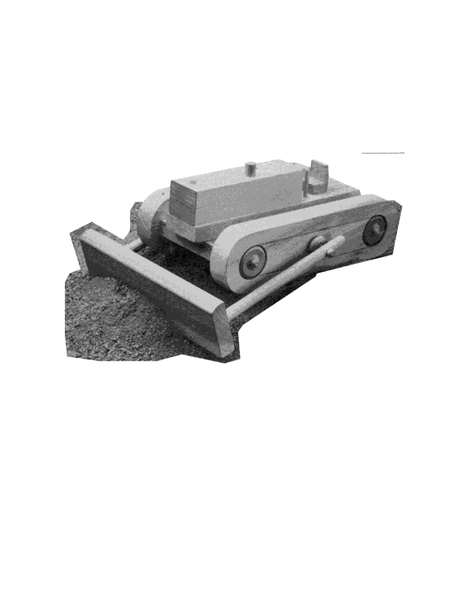
Toy Bulldozer
Kids know quite a bit about playing, after all they work pretty hard at it. And if
there is one thing we adults know about kids at play, it’s that they rarely pass up
an opportunity to play in dirt, which perhaps explains why a toy like this will
always be popular. After all, a bulldozer needs some dirt to push around - the
more the better. Just about any wood can be used to make this project, even pine,
although a hardwood will stand up better as the years go by.

Toy Bulldozer Materials List
Part
Description
Size
No. Req’d
A
Undercarriage
3/4" x 4" x 9"
1
B
Base
3/4" x 2" x 9-1/2"
1
C
Engine
3/4" x 1-3/4" x 6"
2
D
Exhaust
1/2" dia. x 1" long
1
E
Radiator Cap
1/4" dia. x 3/4" long
1
F
Control Lever
3/16" dia. x 2" long
2
G
Seat Cushion
1/2" x 1" x 5/8"
1
H
Seat Back
1/4" x 1" x 1-/4"
1
I
Track
1" x 2-3/4" x 10"
2
J
Blade
3/4" x 2-1/2" x 9"
1
K
Blade Arm
1/2" dia. x 7-1/2" long
2
L
Spacer
1" dia. x 1/4" thick
2
M
Spacer Peg
See detail
2
N
Track Wheel
1-1/2" dia. x 1/2" thick
4
O
Track Wheel Peg
See detail
4
P
Wheel
1" dia. x 1/2" thick
4
Q
Wheel Peg
See detail
4
Toy Bulldozer Complete Schematic
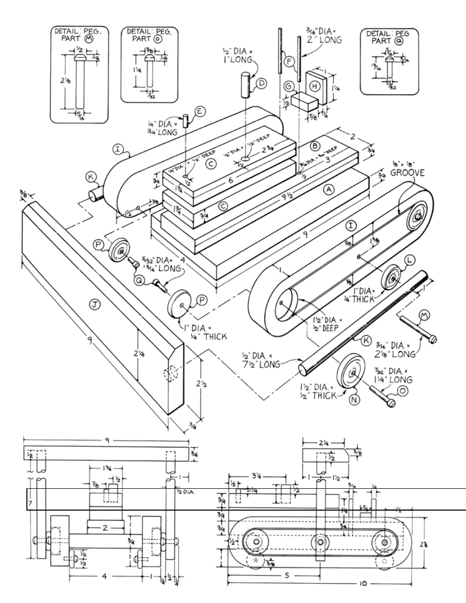

Toy Bulldozer Step-by-Step Instructions
Step 1: Make the Under Carnage (A), the Base (B), and the Engine (C)
1. Cut the undercarnage (part A), the base (part B), and the engine (parts C) to
the dimensions shown on the drawing.
2. Drive a couple of small brads into one of the mating surfaces
3. Snip the heads off the brads so about 1/16" protrudes—this will keep the
glued parts from sliding when glamped.
4. Assemble the two parts C with glue and clamp securely.
5. Allow the glue to dry overnight.
6. Remove the clamps.
7. Locate and drill the holes for parts D and E as shown.
8. Use clipped brads again to keep the parts from sliding, and glue and clamp
parts A and B to parts C.
Step 2: Make the Racks
1. Cut five-quarter stock to a width of 2-3/4" and a length of 10" to make the
two tracks (I).
2. Lay out the location of the 1-1/2" diameter by 1/2" deep holes on each end.
3. Use a 1/8" diameter spade bit or Forstner bit to drill the holes.
4. Use a router equipped with an edge-guide and a 1/8" diameter bit to cut the
1/8" deep x 1/8" wide grooves,
5. Use a compass set for a radius of 1-1/2" to mark the curves on each end of
the tracks.
6. Use a band or saber saw to cut out the curves.
Step 3: Obtaining the Lathe-Turned Pieces
Lathe turn the the spacers (parts L), track wheels (parts N), wheels (parts P),
spacer pegs (parts M), track wheel pegs (parts O), and wheel pegs (parts Q) to the
dimensions shown, or obtain them from a wood craft or hobby store.
Step 4: Make the Blade
1. Cut 3/4" thick stock to a width of 2-1/2" and a length of 9" to make the
blade (J).
2. Use a table saw or hand plane to apply the beveled edge.
3. Locate and mark the location of the two ‘1/2" diameter holes.
4. Bore each hole to a depth of 1/2".

Step 5: Assemble Parts A, B, C, and I
1. Use clipped brads to keep parts A, B, C, and I from sliding when glued.
2. Use glue to assemble the undercarriage (part A), along with the base (part
B) and engine (parts C), to the two tracks (parts I).
3. Clamp firmly. NOTE: Since the long-grain of parts A is joined to the
long-grain of parts I, the glue joint will be as strong as the wood itself,
so no splines or dowel pins are needed.
4. Allow the glue to dry overnight.
Step 6: Cut and Assemble the Remaining
Pieces
1. Cut the various remaining pieces can to size.
2. Assemble the remaining pieces as shown.
3. Use glue and clamp where necessary.
4. Glue the track wheels (N) to parts I as they are purely decorative.
5. Avoid getting excess glue on the blade arms (parts K) as they must be free
to pivot.
6. Blue part M is glued to part I.
7. Avoid getting glue on parts L, as these parts should be free to turn.
Step 7: Sand and Finish
1. Give the completed project a thorough final sanding, taking special care to
round all sharp edges and corners.
2. Make sure all small parts are securely fastened to prevent them from becom-
ing a choking hazard to small children.
3. Leave unfinished.
These plans were originally published in Volume 8, Issue 2 of The Woodworker’s
Journal (Mar./Apr. 1984, pages 48-49).
Wyszukiwarka
Podobne podstrony:
(madera) Woodworking plans Workbench Popular Mechanics Hard Maple
eBook DIY Woodworking Plans Guide To Wood Finishing
2 Woodworking plans settletable
(EBooks) DIY Woodwork Plans 10 Workbench Accessories
Woodworking Plans Garden Bench(1)
2 Woodworking Plans Standing Router Table
Woodworking Plans Timber Garden Shed Part I
2 Woodworking Plans Timber Bookcase
2 woodworking plans trestletable
Diy Workshop Woodwork Plans Drawings For Homemade Wood Lathe
Woodwork Plans Workbench
WoodWorking Plans Roll out Shelves
(Ebooks) DIY Woodwork Plans Drill Press Table
(Ebooks) Diy Woodwork Plans Kitchen Cabinets
2 Woodworking Plans Oakplate
Crafts Woodworking Plans (ebook) candle holder
Crafts Woodworking Plans (ebook) workstation
więcej podobnych podstron