09.04.13
Aircraft Radio Com m unications Receiver
www.aaroncake.net/circuits/aircraftrecv.asp?showcom m ents=all
1/7
Aircraft Radio
Communications Receiver
Communications Receiver
Search:
Search
Author
Views
Views Today
Rank
Comments
161,771
47
46
The communications between commercial aircraft and the ground can be interesting, amusing and
sometimes even disturbing. However radios that receive the approximately 220MHz to 400MHz
band commonly used for aircraft (both military and commercial) are not easily found. And scanners
can be complicated, large and expensive. With an easy to build circuit such as this one, everyone can
enjoy listening in on these conversations.
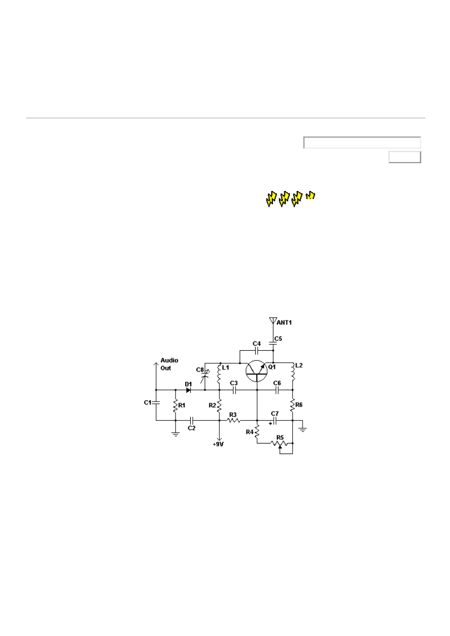
Schematic
Parts
Part
Total
Qty.
Description
Substitutions
R1, R3
2
47K 1/4W Resistor
R2
1
10K 1/4W Resistor
R4
1
4.7K 1/4W Resistor
R5
1
5K Linear Taper Pot
R6
1
2.2K 1/4W Resistor

09.04.13
Aircraft Radio Com m unications Receiver
www.aaroncake.net/circuits/aircraftrecv.asp?showcom m ents=all
2/7
C1, C2,
C3, C6
4
0.001uF Ceramic
Disc Capacitor
C4
1
2.2pF Ceramic Disc
Capacitor
C5
1
1pF Ceramic Disc
Capacitor
C7
1
15uF 15V
Electrolytic
Capacitor
C8
1
18pF Variable
Capacitor
D1
1
1N82 Diode
Q1
1
2N918 NPN
Transistor
L1
1
See Notes
L2
1
1.8uH Inductor
ANT1
1
Approx. 18 Inch Wire
Antenna
MISC
1
PC Board, Wire,
Knob For C8
Notes
1.
The circuit originally appeared in the Think Tank column of the Sept. 1995 issue of Popular
Electronics.
2.
L1 is made by winding 2 turns of 22 AWG magnet wire on a 5/32 drill bit. This inductor can be
modified to shift the frequency range of the circuit.
3.
The antenna can also be placed at the anode of D1 if overload is a problem with it connected to
the emitter of Q1
4.
R5 adjusts regen and thus sensitivity.
Related Circuits
Aircraft Radio Communications Receiver
Ad muted.
We'll do our best to show you more
relevant ads in the future.
Help us show you better ads by
updating your
www.abschirmung.com
Europäischer Hersteller von Abschirmungen aus MuMetall

09.04.13
Aircraft Radio Com m unications Receiver
www.aaroncake.net/circuits/aircraftrecv.asp?showcom m ents=all
3/7
Comments
aircraft communicationAircraft Radio
Communications Receiver
Wednesday, January 25, 2012
11:45:58 PM
I have a gmrs twoway radio it keys from 110.9 to @36.5 MHz. Will anybody hear me in a airplane. If
they are not to far away my call is k6cal I am in San Jose CA
Aircraft Radio Communications Receiver
Wednesday, August 17, 2011
5:05:40 PM
One thing I forgot to mention in my previous comment was that the 2N3904 transistor will not work at
400MHz, but the SF245 transistor used in the Czech circuit will. The 2N3904 transistor will work fine
in the audio stage, however.
Aircraft Radio Communications Receiver
Wednesday, August 17, 2011
4:37:48 PM
Please see the circuit at: http://krysatec.benghi.org/phprs/view.php?cisloclanku=2006033102 It's in
the Czech language, but you can translate it and the schematic does not need any translation. The
ideas of using a front end buffer and an audio amp stage can help this type of receiver circuit quite a
bit. I like the circuit on the above website, but the values of the coil and tuning cap need to be
changed to tune the newer air band. I'm not sure what else may need to be changed at this point to
accommodate the higher frequencies.
Aircraft Radio Communications Receiver
Monday, March 07, 2011
12:25:51 AM
it does really work?
Aircraft Radio Communications Receiver
Thursday, August 12, 2010
12:53:00 AM
I biuld this circuit but I receive no signal (yet)... I used a 2N5179 instead of 2N918. 1N34A instead of
1N82. And a C7 of 22uF (not 15uF). The other parts are same as needed. Do you have any
comments about these replaces?. Thank you very much.
Aircraft Radio Communications Receiver
Tuesday, April 27, 2010
12:34:35 PM
I built it and works! I replaced 2n918 with a 9018 with a frequency transition of 1100 mhz! I made L2
with 28 turns of 0,6 mm wire on 7mm drill bit , 1.6 cm long. Also a diode 1n34 works fine!
Aircraft Radio Communications Receiver
Saturday, October 17, 2009
12:48:32 PM
My research indicates that the 1N82 is a germanium diode from the fifties. A 1N34 should work as a
replacement. A normal silicon diode will not work well as a Germanium diode has a 0.3V forward drop
and a silicon diode has a 0.7V forward drop.
Aircraft Radio Communications Receiver
Wednesday, July 29, 2009
5:40:37 AM
does it work?
Aircraft Radio Communications Receiver
Friday, July 17, 2009 9:24:00
PM
for air band i am using a 3.5 turn coil of wire on a 3/8 in. coil form the wire is 22ga.
Aircraft Radio Communications Receiver
Tuesday, July 14, 2009 1:07:34
AM
its really fantastic opertunity to see this circuit & to create it
Friday, July 03, 2009 12:09:33

09.04.13
Aircraft Radio Com m unications Receiver
www.aaroncake.net/circuits/aircraftrecv.asp?showcom m ents=all
4/7
Aircraft Radio Communications Receiver
PM
How can we change the range of this radio to 118~137MHz?
Aircraft Radio Communications Receiver
Wednesday, June 24, 2009
5:00:27 PM
Can I replace diode 1N82 for 1N60? If no, what diode can I replace 1N82?
Aircraft Radio Communications Receiver
Friday, June 19, 2009 2:22:09
PM
you can obtain a 2N918 transistior from mouser electronics web site a MPS2222A transistor will only
work on air band 117137 mhz not 220400mhz.
Aircraft Radio Communications Receiver
Monday, May 04, 2009 9:52:23
PM
A more common subsistute for 2N918 would be nice.
Aircraft Radio Communications Receiver
Monday, March 23, 2009
4:46:52 AM
Q1 can also be a BFX73 transistor.
Aircraft Radio Communications Receiver
Thursday, March 12, 2009
6:35:38 AM
I can't get my hands on the 1n82 diode. Can anyone suggest some replacements? Also the diode
seems to be connected in reversed bias. Is this an error or on purpose?
Aircraft Radio Communications Receiver
Friday, January 23, 2009
3:03:53 PM
Has anyone tested this receiver????
Aircraft Radio Communications Receiver
Thursday, January 15, 2009
10:10:52 PM
I am a novice. Where is audio out and power in? Can someone confirm my observation before I build
this scanner? 1(+) positive side of microphone or speaker tap in at base of Q1 between C3 and C6.
2() Negative of speaker tap in at Q1 emitter at top of L2. 3Power in at top of C5, power out to
positive at R2 at +9V This appear to be the best way.
Aircraft Radio Communications Receiver
Sunday, January 11, 2009
9:41:59 PM
this radio is a very well built project it is very stable. when you are building this receiver keep all the
leads as short as possible. otherwise you will have problems getting the radio to work. i have not tried
the radio on 220400 mhz.
Aircraft Radio Communications Receiver
Saturday, January 10, 2009
1:55:47 AM
total information is not given
Aircraft Radio Communications Receiver
Saturday, November 15, 2008
6:50:59 AM
It is avery wonderful circuit.and it is very simpal for new electronic field commers. thank you
Aircraft Radio Communications Receiver
Thursday, November 06, 2008
7:09:13 AM
Are you sure this circuit is OK. How does the diode conduct anything at all.It is biased off
permanently. My own receiver taps audio from the junction of C3 and R2.No diode needed. For
filtering out the squelch oscillation put R1 in place of the diode and take the audio from C1.
Aircraft Radio Communications Receiver
Wednesday, October 15, 2008
5:41:00 AM
Ok, I had to dig deep to find any schematics to make a really cheap aircraft scanner, but I found

09.04.13
Aircraft Radio Com m unications Receiver
www.aaroncake.net/circuits/aircraftrecv.asp?showcom m ents=all
5/7
one... And its easier than you think! I bought a $5 am / fm radio from the dollar store. I took it apart
and literally just used a screw driver to seperate the FM tuner coil (1 of 2 copper coils you'll see on
inside). I pushed it far enough apart without breaking where it was soldered to the green board to
change the range to 109mhz 135 mhz.... The catch? Without further modification you always hear
the background static.... That and since it was a $5 radio, you pretty much have to be right at the
airport to pick up anything... Maybe with a slightly more expensive one and a better antenna you could
pick up more..... But for $5, you can't beat the results....
Aircraft Radio Communications Receiver
Friday, October 10, 2008
1:41:58 PM
flyingfish7000: I remember as a kid having a radio that could also recieve uhf/vhf and when i took it
apart and played with the tuning circuitry, i could hear the plane talk at the airport nearby................
Aircraft Radio Communications Receiver
Tuesday, August 12, 2008
6:36:48 AM
what's a range of this tranmitter and what's range of AWG
Aircraft Radio Communications Receiver
Thursday, July 10, 2008 6:33:55
PM
I live near BWI and listen to the tower, ground control, Patomac Approach, and Departure. All of
them communicate between 108 132 Mhz. According to my sectional charts all domestic ATC com.
is on these frequencies. It happens that 108 Mhz is the top end of the FM broadcast band 88 108
Mhz. Can an off the shelf FM receiver be retuned to receive 108 132 mhz?
Aircraft Radio Communications Receiver
Wednesday, July 02, 2008
10:17:17 PM
i read your document its nice and useful. i would like to do a rc plane could you help me in doing that rc
receiver and transmitter
Aircraft Radio Communications Receiver
Thursday, April 17, 2008
12:10:32 AM
ATC is all Amplitude Modulation operating at the VHF Anyone built this? What is it like? Can you
hear any communications ?
Aircraft Radio Communications Receiver
Monday, April 07, 2008 2:35:04
PM
please can i get a qualitative note on how this circuit works,its limits, its range and how it can be built.
thanks
Aircraft Radio Communications Receiver
Sunday, March 23, 2008
12:00:58 PM
I have difficulties in finding the diode 1N82 (or NTE112 for a substitution as marked in comments) , I
need help for finding more equivalent parts , please let me know
Aircraft Radio Communications Receiver
Friday, March 07, 2008
11:26:12 PM
Audio output is not enough to drive a speaker. Use the audio out to drive a 1 or 2 transistor audio
amp. Most air traffic between 108 & 135mhz is AM. This circuit is for 220 400 mhz. Im not sure if
they use AM up there or not. Im also not sure civilian aircraft operate up there. I always thought that
220 400 was military. I hope this helped. kg6ath
Aircraft Radio Communications Receiver
Thursday, March 06, 2008
10:47:18 AM
sir, i want to set up this system for my school laboratary. i want more ground. and how it will be
powered.
Aircraft Radio Communications Receiver
Tuesday, February 26, 2008
12:02:30 AM

09.04.13
Aircraft Radio Com m unications Receiver
www.aaroncake.net/circuits/aircraftrecv.asp?showcom m ents=all
6/7
quite good, but is this practically applicable with low audio output speakers?????????
Aircraft Radio Communications Receiver
Thursday, February 14, 2008
7:08:45 AM
i want to do this project
Aircraft Radio Communications Receiver
Thursday, February 07, 2008
2:28:07 AM
Just curious, is there a way to simply modify a simple am/fm stereo to pick up aircraft bands? Also is
the transmission in FM or AM? I've read documentation giving conflicting responses...I'd lean towards
AM since the radios at work seem to pick up a lot of static when actually emitting sound (Noise
reduction I believe helps this when not picking up a signal).....Oh and one other thing....I don't know
about the rest of the world, but at least at my airport the comms range is from around 117 125 mhz
(approach and ground) and goes as high as 140 mhz (airline ops)......Are those freqs for centers or
as aforementioned? Thanks for the schematics though.
Aircraft Radio Communications Receiver
Wednesday, January 30, 2008
10:24:46 AM
COMPONENT D1 IS THE WRONG WAY ROUND ON THE CIRCUIT
Aircraft Radio Communications Receiver
Monday, January 28, 2008
4:15:21 AM
i want recever circuit
Aircraft Radio Communications Receiver
Tuesday, January 22, 2008
7:43:22 AM
In terms of seminar paper how do someone get a reliable information on this project.
Aircraft Radio Communications Receiver
Wednesday, January 16, 2008
11:47:14 AM
A substitution for the 1N82 is the NTE 112
Aircraft Radio Communications Receiver
Tuesday, January 15, 2008
9:17:08 AM
Can someone tell if this works??
Aircraft Radio Communications Receiver
Sunday, January 13, 2008
9:43:07 AM
SIR WILL U KINDLY PLEASE TELL ME THAT WHAT KIND OF AUDIO OUTPUT CAN BE USED,I
AM USING A SIMPLE AUDIO SPEAKER OF 8OHM.WHAT IS THE RADIUS OF CATCHING THE
PARTICULAR FREQUENCY.
Aircraft Radio Communications Receiver
Thursday, January 10, 2008
10:42:44 AM
Hello Sir I decided to do your ideas in my project if i get success, its because of you so advance
thank but it really works na..........
Aircraft Radio Communications Receiver
Thursday, January 10, 2008
8:51:35 AM
Can not find the 1N82 Diode, is there any substitutions for this part
Aircraft Radio Communications Receiver
Thursday, December 20, 2007
4:33:15 PM
What should the audio output be hooked to? A speaker, an amplifier, or a pizeoelectric earphone?
Aircraft Radio Communications Receiver
Tuesday, December 11, 2007
4:18:59 PM
I have a question about the Variable capacitor. U have one value, 18pf. Would it be possible to get
the full range of the capacitor?

09.04.13
Aircraft Radio Com m unications Receiver
www.aaroncake.net/circuits/aircraftrecv.asp?showcom m ents=all
7/7
Aircraft Radio Communications Receiver
Friday, November 30, 2007
1:44:11 AM
hi sir iam going to communication between small air carft so that i need high range tansmitter and
recivier would u like to help me.
< Back
Forward >
Remote
Mail Me
Search
www.schirmung2000.de
EMVDichtungen, Klebebänder, Vlies u. Kabelschirmung mit bis zu 120 dB
Wyszukiwarka
Podobne podstrony:
Radio Communications
Communication system Radio and TV (134)
7 Mhz receiver PCB dds4 ze strony hamradio india
Communication system Radio and TV (tłumaczenie)
radio jako medium audialne
radio i sport
(ebook PDF)Shannon A Mathematical Theory Of Communication RXK2WIS2ZEJTDZ75G7VI3OC6ZO2P57GO3E27QNQ
CLE Grammaire Progressive du Francais avec 400 exercices (niveau debutant volume2 CORRIGES)
Instrukcja radio Gamma V PL
Bmw 01 94 Business Mid Radio Owners Manual
400 man
400 401
220 2id 29583
220
zestawy radio
RADIO HELLO
więcej podobnych podstron