U.S. ARMY MEDICAL DEPARTMENT CENTER AND SCHOOL
FORT SAM HOUSTON, TEXAS 78234-6100
OPERATING ROOM
TABLE
SUBCOURSE MD0370 EDITION 100

DEVELOPMENT
This subcourse is approved for resident and correspondence course instruction. It
reflects the current thought of the Academy of Health Sciences and conforms to printed
Department of the Army doctrine as closely as currently possible. Development and
progress render such doctrine continuously subject to change.
ADMINISTRATION
Students who desire credit hours for this correspondence subcourse must enroll in the
subcourse. Application for enrollment should be made at the Internet website:
http://www.atrrs.army.mil. You can access the course catalog in the upper right corner.
Enter School Code 555 for medical correspondence courses. Copy down the course
number and title. To apply for enrollment, return to the main ATRRS screen and scroll
down the right side for ATRRS Channels. Click on SELF DEVELOPMENT to open the
application; then follow the on-screen instructions.
For comments or questions regarding enrollment, student records, or examination
shipments, contact the Nonresident Instruction Branch at DSN 471-5877, commercial
(210) 221-5877, toll-free 1-800-344-2380; fax: 210-221-4012 or DSN 471-4012, e-mail
accp@amedd.army.mil, or write to:
NONRESIDENT INSTRUCTION BRANCH
AMEDDC&S
ATTN:
MCCS-HSN
2105 11TH STREET SUITE 4191
FORT SAM HOUSTON TX 78234-5064
Be sure your social security number is on all correspondence sent to the Academy of
Health Sciences.
CLARIFICATION OF TERMINOLOGY
When used in this publication, words such as "he," "him," "his," and "men" 'are intended
to include both the masculine and feminine genders, unless specifically stated otherwise
or when obvious in context.
USE OF PROPRIETARY NAMES
The initial letters of the names of some products may be capitalized in this subcourse.
Such names are proprietary names, that is, brand names or trademarks. Proprietary
names have been used in this subcourse only to make it a more effective learning aid.
The use of any name, proprietary or otherwise, should not be interpreted as
endorsement, deprecation, or criticism of a product; nor should such use be considered
to interpret the validity of proprietary rights in a name, whether it is registered or not.

MD0370 i
TABLE OF CONTENTS
Lesson
Paragraphs
INTRODUCTION
1.
OPERATING ROOM TABLE
Section
I.
Operating
Procedures........................................... 1-1--1-5
Section
II.
Malfunctioning Components ................................. 1-6--1-7
Exercises
APPENDIX, OPERATING ROOM TABLE TROUBLESHOOTING GUIDE

MD0370 ii
CORRESPONDENCE COURSE OF
THE U.S. ARMY MEDICAL DEPARTMENT CENTER AND SCHOOL
SUBCOURSE MD0370
OPERATING ROOM TABLE
INTRODUCTION
As a Medical Equipment Repairer, it is your job to ensure that the field operating
table functions properly and that its operation is safe for both patients and equipment
operators. One way that you accomplish this crucial objective is to isolate malfunctions
and make the required repairs.
Subcourse Components:
This subcourse consists of one lesson and an appendix.
Lesson 1, Operating Room Table
Appendix,
Operating
Room
Table Troubleshooting Guide.
Here are some suggestions that may be helpful to you in completing this
subcourse:
--Read and study each lesson carefully.
--Complete the subcourse lesson by lesson. After completing each lesson, work
the exercises at the end of the lesson, marking your answers in this booklet.

MD0370 iii
--After completing each set of lesson exercises, compare your answers with those
on the solution sheet that follows the exercises. If you have answered an exercise
incorrectly, check the reference cited after the answer on the solution sheet to
determine why your response was not the correct one.
Credit Awarded:
Upon successful completion of the examination for this subcourse, you will be
awarded 4 credit hours.
To receive credit hours, you must be officially enrolled and complete an
examination furnished by the Nonresident Instruction Branch at Fort Sam Houston,
Texas.
You can enroll by going to the web site http://atrrs.army.mil and enrolling under
"Self Development" (School Code 555).
A listing of correspondence courses and subcourses available through the
Nonresident Instruction Section is found in Chapter 4 of DA Pamphlet 350-59, Army
Correspondence Course Program Catalog. The DA PAM is available at the following
website: http://www.usapa.army.mil/pdffiles/p350-59.pdf.

MD0370 1-1
LESSON ASSIGNMENT
LESSON 1
Operating Room Table.
TEXT ASSIGNMENT
Paragraphs 1-1 through 1-7 and Appendix.
LESSON OBJECTIVES
After completing this lesson, you should be able to:
1-1.
Unpack and prepare the operating room table
for
use.
1-2.
Disassemble and inspect the table.
1-3.
Isolate malfunctions of the table.
1-4.
Replace parts of the operating room table, to
include the x-ray tops; head section; leg
sections; back section; back lift assembly; lateral
and drive screw assemblies; seat section,
trunnion, and bearing; vertical gear box
assembly; and column assembly.
SUGGESTION
After completing the assignment, complete the
exercises at the end of this lesson. These exercises
will help you to achieve the lesson objectives.
MD0370 1-2
LESSON 1
OPERATING ROOM TABLE
Section I. OPERATING PROCEDURES
1-1. GENERAL
a. The field operating room table, Model E 99-001, is a compact, easily
transportable unit. It is specifically designed for field use and has all the features
necessary for performing major surgical operations. When folded for storage or
shipment, the operating table and its accessory table are conveniently and securely
strapped into the shipping container furnished with the unit.
b. The operating table is completely mechanical. It contains no electrical,
hydraulic, or pneumatic elements. All controls and locking devices are hand-operated
and easily accessible. The all-weld base is designed to be water-filled for maximum
stability. It is also equipped with four large caster wheels for mobility and four
retractable foot pads for stationary positioning during surgery.
1-2.
UNPACK THE UNIT
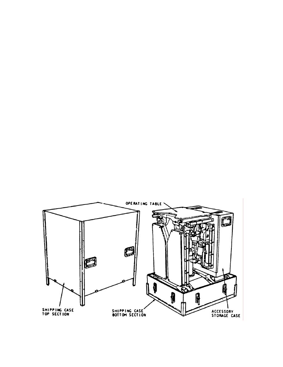
Use the following procedures to unpack the operating table. Refer to figure 1-1
for illustrations of the shipping and storage cases.
Figure 1-1. Shipping and storage cases.

MD0370 1-3
a. Unlatch and remove the shipping case top.
NOTE:
Place latch clips in the down position to prevent accidental injury to the lower
leg or ankle.
b. Remove the accessory storage case and set it aside.
c. Unfasten the hold-down straps which secure the base of the operating table
to the bottom of the shipping case. Lift the operating table out of the bottom of the
shipping case.
NOTE:
The operating table weighs approximately 225 pounds. At least four people
may be required to remove it from the bottom case.
d. The foot pads should be in the raised position when the unit was removed
from the case. If they are in the down position, lift the U-handles to raise them. The
unit should now be resting on all four casters. Roll the unit to the desired location and
then depress the U-handles to lower the foot pads. The unit is now in its stationary
position.
e. If used, remove the tape straps which secure the release pins to the operating
table.
1-3. PREPARE
THE UNIT FOR USE
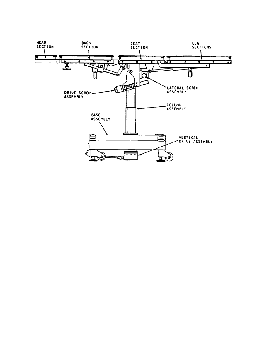
Before operating the operating table, perform the following procedures. Refer to
figure 1-2 for an illustration of the major components.
a. Lift the back section of the table until the release pins can be inserted into the
holes of the V-shaped cast hangers and the pivot holes of the back link adjustment
assemblies
b. Raise each leg assembly to the horizontal position. Use a ratchet assembly
to set the leg sections to any desired position.
c. Check to see if the drain plug is present and tightened.
d. Remove the filler plug and fill the base with water. Re-install and hand tighten
the filler plug.
e. Open the accessory storage case. Remove the head section.
NOTE:
Carefully observe how the accessories are placed in the storage case. The
accessories must be repacked in the reverse order that you removed them to
ensure that the accessory case lid closes properly.
MD0370 1-4
Figure 1-2. Major components.
f. Loosen the clamp knobs beneath the front end of the back section. Guide the
head extender rods into the bearing holes at the front end of the back section. Slide the
head section rods all the way in. Hand tighten the clamp knobs.
g. Remove the mattress pads from the storage case. Turn the pads over so the
elastic bands are facing up. Carefully remove the Formica x-ray tops from each table
top section. Lay the tops face down (mount pins up). Pull the elastic straps up and
over each pin.
CAUTION:
USE EXTREME CAUTION when removing the x-rays tops. They are
made of Formica and can be easily broken.
h. Remove the remaining parts from the storage case and install them on the
side rails of the table top.
1-4. PERFORM
OPERATIONAL CHECK-OUT PROCEDURES
To ensure that the table operates properly, perform the following procedures.
a. Visually inspect the condition of the operating table for loose, broken, or
missing parts.

MD0370 1-5
b. When water is added, check for leakage at the drain plug.
c. Raise the column to the full up position. Check the column to make certain it
is clean and properly lubricated.
d. Check the stability of the unit with the foot pads down. Then, raise the foot
pads and check the clearance between each raised caster wheel and the floor. It
should be 1/8th inch. If not, the clearance can be adjusted by grasping the pad and
turning the jack shaft into or out of the base.
e. Insert each handle assembly. Operate each section of the table top to ensure
proper operation.
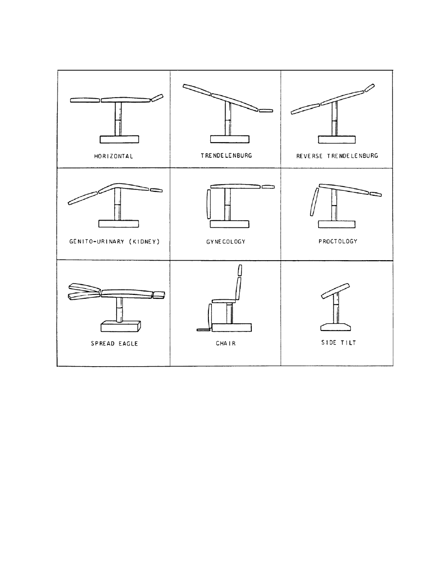
1-5. OPERATIONAL
DESCRIPTION
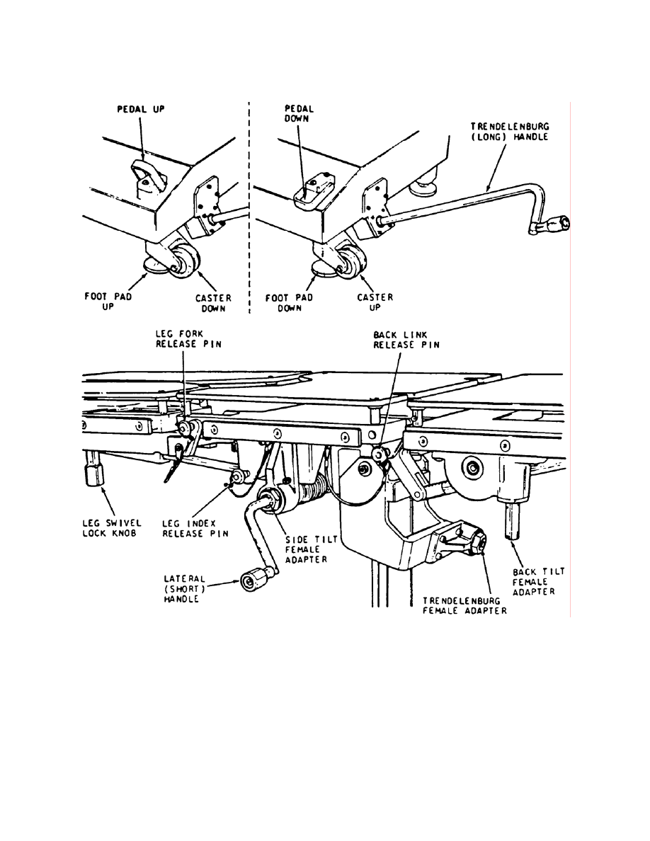
There are nine table positions and articulations (see figure 1-3). Figure 1-4
shows the controls of the operating table. Use the following procedures to operate the
controls of the operating table.
a. Foot Pad Control. Use the U-shaped pedals located on the four corners of
the base to raise and lower the foot pads.
(1) Ensure that when the pedals are down, the foot pads rest on the floor.
(2) Ensure that when the pedals are up, all four casters clear the floor by
approximately 1/8 inch.
b.
Elevation Control. Adjust the height of the operating table by engaging the
long Trendelenburg handle in the head end of the base.
(1) Turn the crank clockwise to raise the table.
(2) Turn the crank counterclockwise to lower the table.
c. Trendelenburg Control. Adjust the Trendelenburg by placing the long
Trendelenburg handle in the drive screw control.
(1) Turn the crank in the counterclockwise direction to adjust the head
down.
(2) Turn the crank in the clockwise direction to adjust the head up.
MD0370 1-6
Figure 1-3. Table positions and articulations.
MD0370 1-7
Figure 1-4. Controls of the operating table.

MD0370 1-8
d. Lateral Control. Adjust the side-to-side tilt by engaging the short lateral
handle in the side tilt control.
(1) Turn clockwise for left tilt.
(2) Turn counterclockwise for right tilt.
e. Head Section Control. Adjust the head section by depressing the release
plate located underneath the head.
(1) From the horizontal position, you can move the head section up 45
degrees or down 45 degrees.
(2) You can extend the head section by unscrewing the clamp knobs and
moving the head to the desired position, then tighten the clamps.
f. Leg Section Control.
(1) To raise the leg section, pull up on each leg until you achieve the
desired position.
(2) To lower the leg section, depress the release latch underneath each
section. You can stop at any position by releasing the release latch.
(3) To spread the legs, unscrew the lock knob under each section and move
it to the desired position.
(4) Tighten each knob after it has been moved.
Section II. MALFUNCTIONING COMPONENTS
1-6. TROUBLESHOOTING
PROCEDURES
You use a troubleshooting guide to help isolate the cause of malfunctions. First,
locate the symptom listed in the guide, and then check the probable causes until you
locate the cause of the malfunction. Refer to the troubleshooting guide in the appendix.
Also, refer to figure 1-2 and figures 1-5 through 1-13 for identification of parts.

MD0370 1-9
1-7. REPLACING
MAJOR
COMPONENTS
Use the procedures described in the following paragraphs to replace defective
parts. Reverse these procedures to reassemble the components.
a. Replace x-ray Tops. Refer to figure 1-2 for an illustration of the major
components. To replace the x-ray tops, perform the following steps:
(1) Depress the release plungers of the two locking posts.
(2) Lift off the x-ray tops.
(3) Reverse the steps to replace the tops. Slide the tops into the holes.
b. Replace the Head Section. To replace the head section (figure 1-13),
perform the following steps:
(1) Refer to figure 1-5. Loosen the knob assembly (part 1) on the underside
of the back section to release the head extension rods.
(2) Withdraw the head section from the mount holes.
(3) Reinstall in the reverse order.
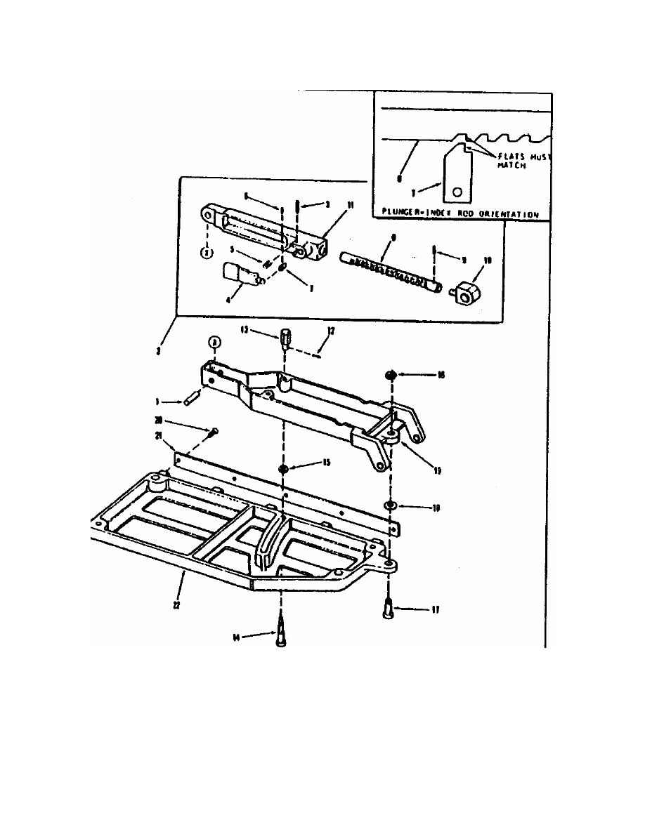
c. Replace the Leg Section. To replace the leg section, perform the following
procedures.
(1) Raise the leg section to the horizontal lock position.
(2) Refer to figure 1-6. Remove the release pin (part 1) and release handle
(part 4) which secures the end of the leg index rod.
(3) Refer to figure 1-6. Support the leg assembly while withdrawing the
pivot pin (part 17) that secures the leg yoke to the seat section of the table.
(4) Lift off the leg section.
(5) Reinstall in the reverse order.
d. Replace the Back Section. To replace the back section, perform the
following procedures:
(1) Raise the back section to the full upright position.
(2) Remove the two back link release pins which are inserted in each pivot
of the back link assemblies (figure 1-5, part 5).

MD0370 1-10
(3) Lean the back section down on a protective mat or cloth to prevent
marring the finish of the back or seat assemblies.
(4) Loosen the two set screws located underneath the seat and below the
back link pivot pins.
(5) Drive out the pivot pins using a brass or soft metal drift punch.
(6) Lift off the back section.
(7) Reinstall in the reverse order.
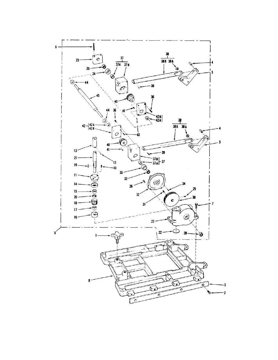
e. Replace the Lift Assembly. To replace the lift assembly, perform the
following procedures:
(1) Raise the back section to the straight up position.
(2) Drive out the dowel pin which secures each gear rack to its back link
assembly (figure 1-6, part 39).
(3) Support the back lift assembly firmly while removing the four capscrews
(Figure 1-6, part 36) at the gear box housing end and the two longer capscrews (figure
1-6, part 6) at the opposite end.
(4) Carefully lift the assembly from the back section.
(5) Reinstall in the reverse order.
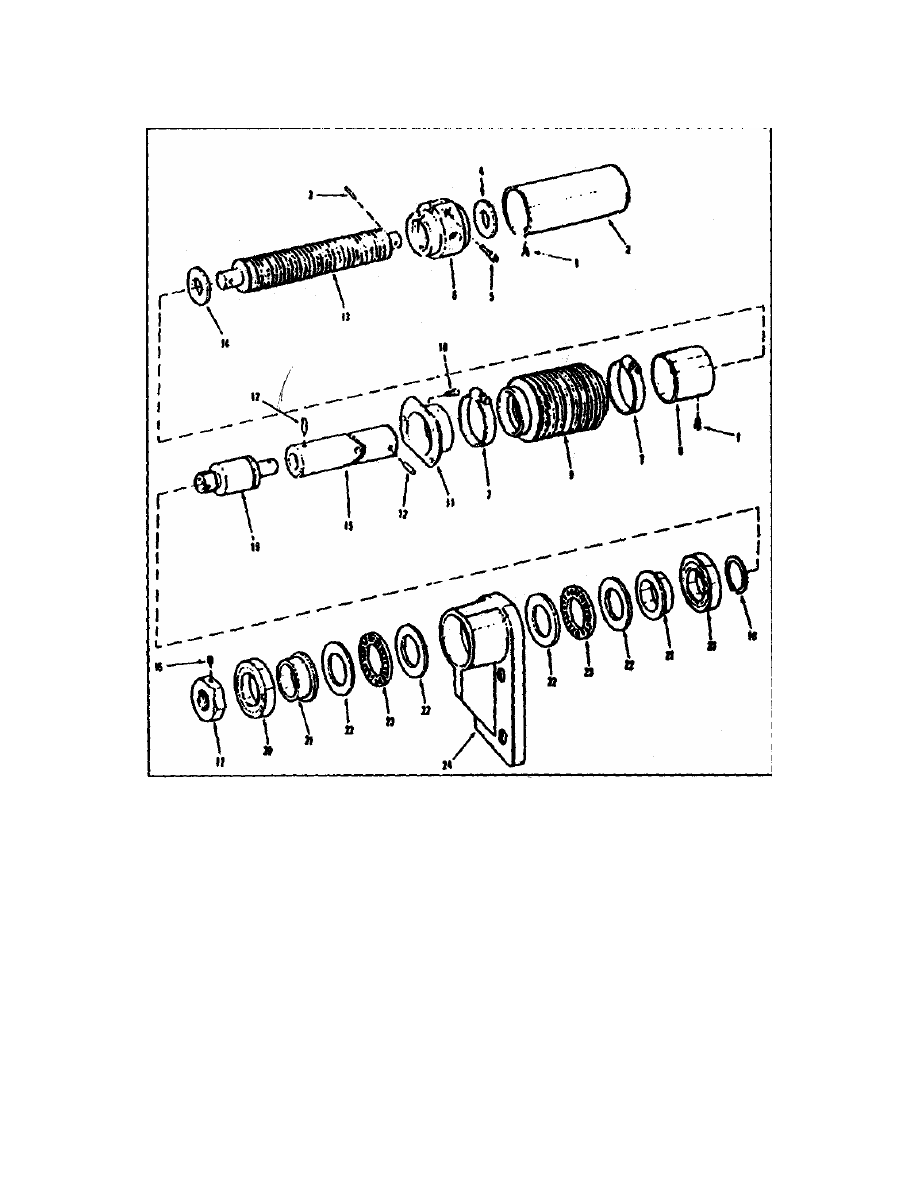
f. Replace the Lateral and Drive Screw Assemblies. To replace the lateral
and drive screw assemblies, perform the following procedures:
(1) Remove the four hex nuts and capscrews that secure the support block
of the drive assembly to the support plate of the seat section. These screws go through
part 24 in figure 1-7.
(2) Loosen the two clamp screws and, while supporting the drive assembly,
pry out the two adjusting pins. Refer to figure 1-8.
(3) Lift the drive assembly from the seat section and trunnion.
(4) Reinstall in the reverse order.

MD0370 1-11
g. Replace the Seat Section, Trunnion, and Bearing. To replace the seat
section, trunnion and bearing, perform the following procedures:
(1) Remove the leg sections, back section, and lateral screw assemblies.
(2) Support the seat section while removing the four capscrews and two
bearing blocks.
(3) Lift off the seat frame and remove the drive screw assembly.
(4) Remove the two retaining rings, nylon washers, and remove the
Trendelenburg pin.
(5) With an assistant supporting the trunnion, remove the two capscrews
and washers. Drive out the lateral pin.
(6) Lift off the trunnion. Take care not to lose the nylon washer located
between the hanger arm of the trunnion and the support arm of the drive screw bracket.
(7) Remove the four capscrews which fasten the drive screw bracket to the
top of the column. Remove the bracket.
(8) Remove the four capscrews which fasten the drive screw bracket to the
top of the column.
h. Replace the Vertical Gear Box Assembly. To replace the vertical gear box
assembly (figure 1-11), perform the following procedures:
(1) With the aid of two or three assistants, carefully turn the operating table
on its side.
NOTE:
Lay the table top on the mats to prevent damage.
(2) Drive out the spring steel pin that secures the universal joint to the end
of the vertical drive gear shaft. Discard the old pin and use a new pin during
reassembly. Remove the four capscrews and the gear box cover (Figure 1-9, part 5).
(3) From inside the gear box, remove the three machine screws that secure
the gear box housing to the bearing retainer at the lower end of the sliding column
(Figure 1-10, part 8).
(4) Remove the five capscrews that secure the gear box housing to the
underside of the base (Figure 1-8, part 15).
(5) Carefully remove the vertical gear box.

MD0370 1-12
(6) Reinstall in the reverse order.
NOTE:
Ensure the retaining ring (figure 1-9, part 11) is firmly in the retaining ring slot
to prevent the worm gear from slipping (figure 1-9, part 12). If the retaining
ring is not in place, the worm gear will slip out of place allowing the entire
column to drop during raising or lowering.
NOTE:
Some units have been modified by the manufacturer using a sheer pin in
place of the retaining ring. Consult your shop modification work orders for the
pin type and placement.
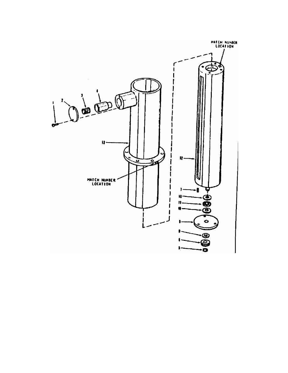
i. Replace the Column Assembly. To replace the column assembly (figure 1-
12), perform the following procedures:
(1) Remove the head and leg sections.
(2) With two or three assistants steadying the assembled back and seat
sections, remove the four capscrews which secure the drive screw bracket to the top of
the column (figure 1-9, part 29).
(3) Remove the entire assembly, as a unit, from the column.
(4) Remove the vertical gear box.
(5) Remove the six capscrews (figure 1-8, part 17) which secure the
mounting flange to the top of the base assembly (figure 1-8, part 18).
(6) Lift out the column assembly.
(7) Reinstall in the reverse order.

MD0370 1-13
NUMBERS
IN
FIGURE
PART NO.
DESCRIPTION
1 2 3 4 56 7
UNITS
PER
ASSY
USEABLE
ON
CODE
COMPLETE LIFT AND BACK SECTION
No Number
LIFT AND BACK SECTION,
Complete
REF
-1
E99-349
KNOB ASSEMBLY, Head
Locking
2
-2
AN505C516R10
SCREW, Machine
(81490 P/N E99-303)
8
-3
E99-123
RAIL, Back
2
-4
E99-326
PIN, Dowel, CRES,
3/8 inch diameter by 1 1/2 inch
2
-5
E99-126
LINK ASSEMBLY, Back
2
-6
E99-485
CAPSCREW, Socket head,
5/16-18 by 1-3/4 inch
2
-7
E99-575
CAPSCREW, Socket head,
5/16-18 by 3/4 inch
4
-8
E99-141
FRAME ASSEMBLY, Back
1
-9
E99-167
BACK LIFT ASSEMBLY,
Complete
1
-10
E99-273
CAPSCREW, Socket head,
10-24 by 3/8 inch
3
-11
E99-140
RETAINER, Bearing
1
-12
MS9047-106
PIN, Spring
(24617 P/N 455862)
1
-13
E99-586
ADAPTER, Crank handle
1
-14
7102-KR
BEARING, Ball (38443)
(81490 P/N E99-329)
1
-15
E99-142
SPACER, Sleeve
1
-16
20201
BEARING, Ball (43334)
(81490 P/N E99-321)
1
-17
E99-144
SPACER, Sleeve
1
-18
E99-283
WORM GEAR
1
-19
E99-275
KEY, Square,
1/8 by 1/8 by 7/8 inch
1
-20
MS16624-3050
RING, Retaining,
(81490 P/N E99-287)
1
Figure 1-5. Complete lift and back section--legend (continued).

MD0370 1-14
NUMBERS
IN
FIGURE
PART NO.
DESCRIPTION
1 2 3 4 56 7
UNITS
PER
ASSY
USEABLE
ON
CODE
COMPLETE LIFT AND BACK SECTION
-21
E99-150
SHAFT, Worm gear
1
-22
P17S
PLUG, Expansion (72741)
(81490 P/N E99-332)
1
-23
E99-148
BLOCK, Support
1
-24
E99-454
SPACER, Sleeve
1
-25
M-10121
BEARING, Roller (60380)
(81490 P/N E99-333)
1
-26
E99-268
CAPSCREW, Socket head,
1/4-20 by 1/2 inch
4
-27
E99-344
HOUSING, Gear box
1
-28
M-10121
BEARING, Roller (60380)
(81490 P/N E99-333)
1
-29 AN565EC416H4
SETSCREW
(81490 P/N E99-453)
2
-30
E99-143
GEAR, worm wheel
1
-31
E99-336
KEY, Square,
3/16 by 3/16 by 1 inch
1
-32
E99-345
COVER, Gear box
1
-33
B-107
BEARING, Roller (60380)
(81490 P/N E99-333)
1
-34
141153
PIN, Dowel, 3/16 inch
diameter by 5/8 inch (24617)
2
-35
E99-147
SPACER, Sleeve
1
-36
E99-268
CAPSCREW, Socket head,
1/4-20 by 1/2 inch
8
-37
E99-452
HOUSING ASSEMBLY,
Gear rack
2
-37A
7102-KR
BEARING, Sleeve
(altered 71041 P/N
B-1013-4)
1
-37B
E99-104
HOUSING, Gear rack
1
-38
E99-456
RACK AND BEARING
ASSEMBLY, Gear
2
-38A
B-68-4
BEARING, Sleeve (71041)
(81490 P/N E99-469)
1
-38B
E99-105
RACK, Gear
1
Figure 1-5. Complete lift and back section--legend (continued).
MD0370 1-15
NUMBERS
IN
FIGURE
PART NO.
DESCRIPTION
1 2 3 4 56 7
UNITS
PER
ASSY
USEABLE
ON
CODE
COMPLETE LIFT AND BACK SECTION
-39
MS9047-172
PIN, Spring
(24617 P/N 456693)
2
-40
E99-149
Gear, Spur
2
-41
E99-336
KEY, Square,
3/16 by 3/16 by 1 inch
2
-42
E99-150
SHAFT, Worm gear
2
-42A
P17S
PLUG, Expansion (72741)
(81490 P/N E99-332)
1
-42B
E99-148
BLOCK, Support
1
-43
141153
PIN, Dowel, 3/16 inch
diameter by 5/8 inch (24617)
4
-44
E99-146
SPACER, Sleeve
2
-45
E99-113
SHAFT, Pinion
1
Figure 1-5. Complete lift and back section--legend (concluded).
MD0370 1-16
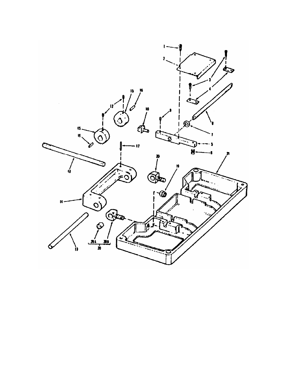
Figure 1-6. Complete lift and back section--diagram.
MD0370 1-17
Figure 1-7. Right and left hand leg and index assemblies (continued.

MD0370 1-18
NUMBERS
IN
FIGURE
PART NO.
DESCRIPTION
1 2 3 4 56 7
UNITS
PER
ASSY
USEABLE
ON
CODE
RIGHT AND LEFT HAND LEG AND INDEX ASSEMBLIES
CODE A-L.H. LEG ASSEMBLY ONLY
CODE B-R.H. LEG ASSEMBLY ONLY
No Number
LEG AND INDEX ASSEMBLY,
L.H.
REF A
No Number
LEG AND INDEX ASSEMBLY,
R.H.
REF B
-1
E99-323
PIN, Dowel
1
-2
E99-004
INDEX ASSEMBLY, Leg
1
-3
MS9047-172
PIN, Spring
(24617 P/N 456693)
1
-4
E99-347
HANDLE, Release
1
-5
E99-156
SPRING, Compression
1
-6
MS9047-099
PIN, Spring
(24617 P/N 456335)
1
-7
E99-107
PLUNGER
1
-8
E99-129
ROD, Index
1
-9
MS9047-164
PIN, Spring
(81490 P/N E99-369)
1
-10
E99-116
BLOCK, Pivot
1
-11
E99-365
HOUSING ASSEMBLY, Index
1
-12
MS9047-106
PIN, Spring
(24617 P/N 455682)
1
-13
E99-536
KNOB, Swivel lock
1
-14
E99-145
SCREW, Clamp
1
-15
E99-051
WASHER, Nylon
1
-16
5131-50H
RING, Retaining, (79136)
(81490 P/N E99-110)
1
-17
E99-158
PIN, Pivot
1
-18
E99-051
WASHER, Nylon
1
-19
E99-362
SUPPORT ASSEMBLY, Leg
1
-20
AN505C516R10
SCREW, Machine
(81490 P/N E99-303)
5
-21
E99-121
RAIL, Leg
1
-22
E99-363
LEG ASSEMBLY, L.H.
1
A
-22
E99-364
LEG ASSEMBLY, R.H.
1
B
-23
No Number
WASHER, Nylon
Figure 1-7. Right and left hand leg and index assemblies (Concluded).
MD0370 1-19
Figure 1-8. Drive and lateral screw assemblies (continued).

MD0370 1-20
NUMBERS
IN
FIGURE
PART NO.
DESCRIPTION
1 2 3 4 56 7
UNITS
PER
ASSY
USEABLE
ON
CODE
DRIVE AND LATERAL SCREW ASSEMBLIES
CODE A-USED ON LATERAL SCREW ASSEMBLY ONLY
CODE B-USED ON DRIVE SCREW ASSEMBLY ONLY
E99-509
SCREW ASSEMBLY, Drive
REF
A
E99-590
SCREW ASSEMBLY, Lateral
REF
B
-1
E99-256
CAPSCREW, Socket head,
5-40 by 3/16 inch
2
-2
E99-112
COVER, Boot, closed end
1
A
-2
E99-087
COVER, Boot, closed end
1
B
-3
MS9047-168
PIN, Spring (96906)
(24617 P/N 456652)
1
-4
E99-065
WASHER, Flat
1
-5
E99-327
CAPSCREW, Socket head,
8-32 by 1/2 inch
1
-6
E99-055
NUT, Adjustment
1
-7
QS-100-MS
CLAMP, Hose (73862)
(81490 P/N E99-258)
2
-8
E99-070
COVER, Boot, straight
1
-9
E99-066
COVER, Expandable
1
-10
E99-256
CAPSCREW, Socket head,
5-40 by 3/16 inch
3
-11
E99-071
COVER, Boot, flanged
1
-12
141159
PIN, Dowel, 3/16 inch
diameter by 1 inch (24617)
2
-13
E99-060
LEADSCREW
1
-14
E00-065
WASHER
1
-15
E99-589
UNIVERSAL JOINT
1
A
-15
E99-189
UNIVERSAL JOINT
1
B
-16
AN565DC416114 SETSCREW, Hex socket head
(81490 P/N E99-315)
1
-17
E99-063
NUT, Lock
1
-18
5100-112H
RING, Retaining, (79H36)
(81490 P/N E99-561)
1
-19
E99-029
SHAFT, Adjustment
1
A
-19
E99-069
SHAFT, Adjustment
1
B
Figure 1-8. Drive and lateral screw assemblies (Continued).
MD0370 1-21
NUMBERS
IN
FIGURE
PART NO.
DESCRIPTION
1 2 3 4 56 7
UNITS
PER
ASSY
USEABLE
ON
CODE
DRIVE AND LATERAL SCREW ASSEMBLIES
CODE A-USED ON LATERAL SCREW ASSEMBLY ONLY
CODE B-USED ON DRIVE SCREW ASSEMBLY ONLY
E99-509
SCREW ASSEMBLY, Drive
REF
A
E99-590
SCREW ASSEMBLY, Lateral
REF
B
-20
B-512-DD
BEARING, Ball (21335)
(81490 P/N E99-262)
2
-21
E99-527
SPACER, Bearing
2
-22
TRB-1828
RACE, Thrust (60380)
(81490 P/N E99-480)
4
-23
NTA-1828
BEARING, Thrust (60380)
(81490 P/N E99-511)
2
-24
E99-150
BRACKET, Bearing
1
Figure 1-8. Drive and lateral screw assemblies (concluded).

MD0370 1-22
NUMBERS
IN
FIGURE
PART NO.
DESCRIPTION
1 2 3 4 56 7
UNITS
PER
ASSY
USEABLE
ON
CODE
OPERATING TABLE COMPONENTS
-1 MS9047-133
PIN,
Spring
(24617 P/N 454516)
3
-2 300-10-B
UNIVERSAL
JOINT
(03705) (81490 P/N E99-193)
1
-3 E99-0125
ROD,
Transfer
1
-4 E99-499 CAPSCREW,
Socket
head,
1/4-20 by 3/4 inch
5
-5 MS35223-79
SCREW,
Machine
(81490 P/N E99-068)
8
-6 E99-062 BRACKET,
Bearing block to base side
1
-7 E99-111 BRACKET,
Bearing block to base bottom
1
-8 E99-087 BLOCK,
Bearing
1
-9 MS9047-137
PIN,
Spring
(81490 P/N E99-369)
1
-10 300-10-B UNIVERSAL
JOINT
(03705) (81490 P/N E99-193)
2
-11 105-KSZZ BEARING, Ball (38443)
(81490 P/N E99-064)
2
-12 5108-100 RING,
Retaining,
(79136) (81490 P/N E99-560)
2
-13
E99-026
ADAPTER, Lift crank
1
-14 MS35223-79
SCREW,
Machine
(81490 P/N E99-068)
3
-15 E99-499 CAPSCREW,
Socket
head,
1/4-20 by 3/4 inch
5
-16 E99-515 GEAR
BOX
ASSEMBLY, Vertical
(see Figure 8 for replacement
parts)
1
-17 E99-499 CAPSCREW,
Socket
head,
1/4-20 by 3/4 inch
6
-18 E99-061 COLUMN
ASSEMBLY,
(see Figure 9 for replacement
parts)
1
-19
S-142
PLUG, Tank inlet
(86343) (81490 P/N E99-089)
1
-20
E99-091
GASKET, Inlet plug
1
Figure 1-9. Operating table components--legend (continued).

MD0370 1-23
NUMBERS
IN
FIGURE
PART NO.
DESCRIPTION
1 2 3 4 56 7
UNITS
PER
ASSY
USEABLE
ON
CODE
COMPLETE LIFT AND BACK SECTION
-21
S-102
PLUG, Tank drain
(86343) (81490 P/N E99-090)
1
-22
E99-092
GASKET, Drain plug
1
E99-012
BASE AND CASTERASSEMBLY
1
-23
E99-539
CAPSCREW, Hex washer
head, 1/4-20 by 1 inch
8
-24
E99-479
CAP, Caster
4
-25
E99-491
PEDAL AND LINK ASSEMBLY
4
-26
E99-522
SLEEVE, Nylon, split
8
-27
E99-484
RETAINER, Spring
4
-28
E99-099
SPRING, Compression
4
-29
E99-097
WASHER, Thrust
4
-30
E99-487
SCREW, Machine, flat head
5/8-11 by 1 3/4 inch
4
-31
E99-044
PAD, Foot
4
-32
E99-043
SHAFT, Jack
4
-33
124925
NUT, Hex jam,
3/8-24 by 3 inches (24617)
4
-34
124128
BOLT, Hex head,
3/8-24 by 3 inches (24617)
4
-35
E99-495
WHEEL, Caster
4
-36
E99-540
SLEEVE, Caster wheel
4
-37
E99-494
RING, retaining
4
-38
E99-489
FORK ASSEMBLY, Caster
4
-39
E99-038
SHAFT, Vertical
4
-40
1612
RACE, Roller bearing (60380)
(81490 P/N E99-478)
8
-41
E99-490
SPACER, Sleeve
4
-42
E99-073
BASE ASSEMBLY, Welded
1
Figure 1-9. Operating table components--legend (Concluded).
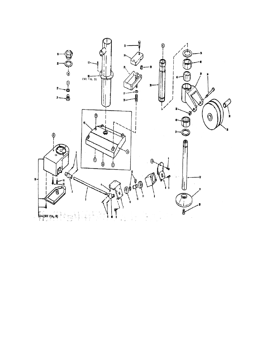
MD0370 1-24
Figure 1-10. Operating table components--diagram.

MD0370 1-25
NUMBERS
IN
FIGURE
PART NO.
DESCRIPTION
1 2 3 4 56 7
UNITS
PER
ASSY
USEABLE
ON
CODE
VERTICAL GEAR BOX ASSEMBLY
E99-515
GEAR BOX ASSEMBLY, Vertical
REF
-1
E99-273
CAPSCREW, Socket head,
10-24 by 3/8 inch
4
-2
E99-379
COVER, Gear box
1
-3
141155
PIN, Dowel, 3/16 inch
diameter by 3/4 inch (24617)
2
-4
M-6101
BEARING, Roller (60380)
(81490 P/N E99-269)
1
-5
E99-541
CAPSCREW, Socket head,
10-24 by 5/8 inch
4
-6
E99-013
RETAINER, Bearing
1
-7
E99-500
LOCKNUT, Special
1
-8
E99-501
LOCKWASHER, Special
1
-9
E99-007
SHAFT, Worm
1
-10
5202-SBKF
BEARING, Ball (38443)
(81490 P/N E99-282)
1
-11
MS16624-3050
RING, Retaining,
(81490 P/N E99-287)
1
-12
E99-283
WORM GEAR
1
-13
E99-275
KEY, Square,
1/8 by 1/8 by 7/8 inch
1
-14
8121
BEARING, Roller (60380)
(81490 P/N E99-267)
1
-15
E99-008
SHAFT, Gear
1
-16
TRB-613
RACE, Thrust (60380)
(81490 P/N E99-276)
2
-17
E99-541
CAPSCREW, Socket head,
10-24 by 5/8 inch
4
-18
E99-009
GEAR, Worm
1
-19
E99-0010
GEAR, Spur
1
-20
M-65
BEARING, Roller (60380)
(81490 P/N E99-265)
1
-21
E99-378
HOUSING, Gear
1
Figure 1-11. Vertical gear box assembly (continued).
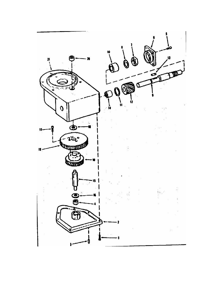
MD0370 1-26
Figure 1-11. Vertical gear box assembly (concluded).
MD0370 1-27
NUMBERS
IN
FIGURE
PART NO.
DESCRIPTION
1 2 3 4 56 7
UNITS
PER
ASSY
USEABLE
ON
CODE
COLUMN ASSEMBLY
E99-061
COLUMN
ASSEMBLY REF
-1
E99-272
SCREW, Machine, pan head
10-32 by 1/2 inch
2
-2
E99-020
COVER, Housing
1
-3
E99-188
SPRING, Compression
1
-4
E99-021
KEY, Column
1
-5
MS16624-3050
RING, Retaining,
(81490 P/N E99-287)
1
-6 E99-011 GEAR,
Worm
1
-7
E99-507
KEY, Square,
1/8 by 1/8 by 7/16 inch
1
-8
TD-812
WASHER, Thrust (60380)
(81490 P/N E99-290)
1
-9
E99-463
RETAINER, Bearing
1
-10
TRD-815
RACE, Thrust (60380)
(81490 P/N E99-284)
2
-11
NTA-815
BEARING, (60380)
(81490 P/N E99-288)
1
-12 E99-512 COLUMN
ASSEMBLY, Sliding
1
-13
E99-504
COLUMN ASSEMBLY, Outer
1
Figure 1-12. Column assembly (continued).
MD0370 1-28
Figure 1-12. Column assembly (concluded).

MD0370 1-29
NUMBERS
IN
FIGURE
PART NO.
DESCRIPTION
1 2 3 4 56 7
UNITS
PER
ASSY
USEABLE
ON
CODE
HEAD SECTION ASSEMBLY
E99-553
HEAD SECTION ASSEMBLY
REF
-1
E99-272
SCREW, Machine, pan head
10-32 by 1/2 inch
4
-2
E99-596
PLATE, Ratchet release
1
-3
E99-272
SCREW, Machine, pan head
10-32 by 1/2 inch
4
-4
E99-591
PLATE, Pivot retainer
2
-5
E99-594
BAR, Actuator
2
-6
490132
SPRING, Compression (24617)
2
-7
E99-028
WASHER, Nylon
2
-8
E99-593
ROD, Pivot
1
-9
AN565AC8112
SETSCREW, Hex socket flat
Point (81490 P/N E99-024)
2
-10
E99-592
PAWL, Actuator
2
-11
E99-316
PIN, Dowel, CRES
3/16 inch diameter by 1 1/4 inch
2
-12
AN565AC1032H3 SETSCREW, Hex socket flat
Point (81490 P/N E99-022)
2
-13
E99-595
SHAFT, Head pivot
1
-14
E99-341
PIVOT, Head frame
1
-15
E99-597
RATCHET, Head
2
-16
E99-023
KEY, Square,
3/16 inch by 3/4 inch long
2
-17
E99-316
PIN, Dowel, CRES,
3/16 inch diameter by 1 1/4 inch
2
-18
E99-101
ROD, Head extension
2
-19
E99-027
NUT, Castle, 1/2 -13NC
2
-20
E99-470
BEARING ASSEMBLY, Pivot
2
-20A
AA-710-19
BEARING, Sleeve (71041)
(81490 P/N E99-309)
1
-20B
E99-151
BLOCK, Bearing
1
-21
E99-339
FRAME, Head
1
Figure 1-13. Head section assembly (continued).

MD0370 1-31
EXERCISES, LESSON 1
INSTRUCTIONS: Answer the following items by completing the statement or by writing
the answer in the space provided at the end of the item.
After you have completed all of these items, turn to "Solutions to Exercises" at the
end of the lesson and check your answers with the solutions.
1. You are adjusting the lateral control for right tilt. You do this by:
a. Raising the lateral handle.
b. Lowering the lateral handle.
c. Turning the lateral handle clockwise.
d. Turning the lateral handle counterclockwise.
2. You are adjusting the head section. Before you move the head section up or
down,
you:
a. Lower the leg sections.
b. Adjust the Trendelenburg (head-on).
c.
Adjust
the
height
of the operating table.
d. Depress the release plate located underneath the head to tilt the head section.
3. You isolated the cause of a malfunction and are replacing the x-ray tops. Which
items do you depress?
a. Back left gear racks.
b. The U-handles to lower the foot pads.
c. The release plungers of the two locking posts.
d. The two clamp knobs on the underside of the back section.

MD0370 1-32
4. You are using the troubleshooting guide (refer to the appendix) to isolate the
cause of a malfunction. The lateral controls are not operable. What is the probable
cause of this malfunction?
a. Transfer rod is not secured with set screws (figure 1-8).
b. Worm gear in the column assembly is worn or stripped (figure 1-10).
c. Female left crank adapter is stripped (figure 1-8).
d. Female adapter collar is stripped (figure 1-7).
5. You are using the troubleshooting guide (refer to the appendix) to isolate the
cause of a malfunction. What would probably cause the back to get stuck in the
lowest position and not rise?
a. The square key (Part 41) is sheared or missing (figure 1-5).
b. The square key (Part 31) is sheared or missing (figure 1-5).
c. The set screw (Part 39) is missing (figure 1-5).
d. The female left crank adapter is stripped (figure 1-8).
6. You are replacing the head section. Before you withdraw the head section from
the mount holes, you:
a. Loosen the clamp knobs on the underside of the back section.
b. Depress the release plungers of the locking posts.
c. Loosen the two set screws located underneath.
d. Adjust the table vertically.

MD0370 1-33
7. You are replacing the defective lateral drive screw assemblies. After you remove
the four hex nuts and capscrews that secure the support block, you:
a.
Adjust
the
gears.
b. Lift the drive assembly from the seat section and trunnion.
c. Loosen the two clamp screws and, while supporting the drive assembly, pry
out the two adjusting pins
d. Remove the leg sections, back section, and lateral screw assemblies.
8. You are replacing the back lift assembly. After you raise the back section to the
straight up position, you:
a. Drive out the dowel pin securing the gear racks to the back link assemblies.
b. Withdraw the release pin securing the leg yoke to the seat section
c. Remove the release pin securing the end of the leg index rod.
d. Support the back section while withdrawing the release pin.
Check Your Answers on Next Page

MD0370 1-34
SOLUTIONS TO EXERCISES, LESSON 1.
1. d
(para 1-5d(2))
2. d
(para 1-5e)
3. c
(para 1-7a(1))
4
d
(Appendix, Troubleshooting Guide)
5. b
(Appendix, Troubleshooting Guide)
6. a
(para 1-7b(1))
7. c
(para 1-7f(2))
8. a
(para 1-7e(2))
End of Lesson 1

MD0370 A-1
APPENDIX
OPERATING ROOM TABLE TROUBLESHOOTING GUIDE
SYMPTOM
01. The head will not stay in place.
02. The table will not raise or lower,
but the crank handle turns freely.
03. The table will not raise.
POSSIBLE CAUSE
1. Actuator pawls in the head section
assembly are maladjusted. (figure 1-11)
2. Pivot retainer plate in the head section
assembly will not move. (figure 1-11)
3. Square key (part 16) in the head
section assembly is missing. (figure 1-11)
4. Set screws (part 12) in the head section
assembly are missing. (figure 1-11)
1. Transfer rod in not secured with set
screws. (figure 1-8)
2. Square key (part 13) is missing. (figure 1-9)
1. Worm gear (part 6) in the column
assembly is worn or stripped. (figure 1-10)
2. Worm gear (part 12) in the vertical gear
box assembly is worn or stripped.
(figure
1-9)
3. Cap screws (part 17) in the vertical gear
box assembly are not installed. (figure 1-9)
4. Worm shaft (part 9) in the vertical gear box
assembly is broken. (figure 1-9)
5. Spring pin (part 9) is broken. (figure 1-8)
6. Worm gear (part 18) in the vertical gear
box assembly is stripped. figure 1-9)
7. Spring pin (part 1) is broken or missing.
(figure
1-8)

MD0370 A-2
APPENDIX (CONTINUED)
SYMPTOM
04. The table is stuck in the down
position and will not raise.
05. The casters are stuck in the down
position.
06. The casters will not raise or lower.
07. There is no lateral control.
08. The table’s lateral controls are not
operable.
09. The back will not raise or lower.
10. Only one side of the back section
will raise or lower.
11. The back is stuck in the lowest
position and will not raise.
12. The back will not raise.
POSSIBLE CAUSE
Female lift crank adaptor is stripped.
(figure
1-8)
Caster cap in not secured. (figure 1-8)
Jack shaft is not secured to the pedal and
link assembly. (figure 1-8)
U-joint (part 15) is broken. (figure 1-7)
Female adapter collar is stripped.
figure
1-7)
Set screw (part 29) is missing. (figure 1-5)
1. The square key (part 41) is sheared or
missing. (figure 1-5)
2. Spring pin (part 39) is broken. (figure 1-5)
Square key (part 31) is missing or
broken. (figure1-5)
1. Worm gear (part 18) is worn smooth.
(figure
1-5)
2. Spring pin (part 12) is sheared. (figure 1-5)
3. Square key (part 19) is broken. (figure 1-5)
4. Female crank handle adapter is stripped.
(figure
1-5)

MD0370 A-3
APPENDIX (CONTINUED)
SYMPTOM
13. Only one side of the back section
will
rise.
14. The leg will not stay in place when
positioned.
15. The table will not go into the
Trendelenburg
position.
16. The head will not move to the
desired
position.
17. The table will not go into the
reverse of forward Trendelenburg
position.
18. The lateral movement function is
not
working.
POSSIBLE CAUSE
Dowel pin (part 4) is missing. (figure 1-5)
1. Screw clamp (part 14) is stripped.
(figure
1-6)
2. Plunger (part 7) has a broken tooth.
(figure
1-6)
3. Spring pin (part 12) has fallen out.
(figure
1-6)
4. Spring pin (part 6) is sheared. (figure 1-6)
1. Female adapter collar is stripped.
(figure
1-7)
2. U-joint is broken. (figure 1-7)
3. Spring pin (part 3) is broken. (figure 1-7)
Ratchet heads are installed 180 degrees
out of alignment. (figure 1-11)
Dowel pin (part 12) is sheared. (figure 1-7)
Spring pin (part 3) is sheared. (figure1-7)
End of Appendix
Document Outline
Wyszukiwarka
Podobne podstrony:
Table Queen Anne Living Room Tables (Coffee, End)
Cliffs of Dover Aircraft Operation Table
Living Room Sofa Table
The uA741 Operational Amplifier[1]
operatory i funkcje matematyczne
operator maszyn lesnych 833[02] o1 03 n
mechanik operator pojazdow i maszyn rolniczych 723[03] z2 04 n
Kierowca operator wózków jezdniowych 833401
oak dining table
mechanik operator pojazdow i maszyn rolniczych 723[03] o1 05 u
OPERAT STABLE VERSION ugoda id Nieznany
operator urzadzen przemyslu szklarskiego 813[02] z2 07 n
4 Steyr Operation and Maintenance Manual 8th edition Feb 08
operator urzadzen przemyslu spozywczego 827[01] z2 02 u
więcej podobnych podstron