Working Instructions, SP/Mechanical
3_00021-1/FEA 209 544/78 C
Sony Ericsson Mobile Communications AB
Approved according to 000 21-LXE 107 42/1
Working Instructions, SP/Mechanical
Applicable for T100/T102/T105/T106
Contents:
1
Disassembly .....................................................................................................................2
1.1
Process Tools.....................................................................................................2
1.2
Equipment..........................................................................................................2
1.3
Instructions ........................................................................................................2
2
Reassembly ......................................................................................................................5
2.1
Process Tools.....................................................................................................5
2.2
Equipment..........................................................................................................5
2.3
Instructions ........................................................................................................5
3
Replacement of Mechanical Parts .................................................................................8
3.1
Front Cover........................................................................................................8
3.2
Microphone......................................................................................................10
3.3
Battery connectors ...........................................................................................11
3.4
Speaker ............................................................................................................12
3.5
Keypad.............................................................................................................13
3.6
Display assembly.............................................................................................14
3.7
Buzzer protection rubber .................................................................................17
3.8
Volume key .....................................................................................................18
3.9
Vibrator Assembly...........................................................................................19
3.10
Antenna Cover Replacement...........................................................................20
4
Process Tools for Label ................................................................................................22
4.1
Instructions ......................................................................................................22
5
Revision History ............................................................................................................23
Working Instructions, SP/Mechanical
3_00021-1/FEA 209 544/78 C
Sony Ericsson Mobile Communications AB
2(23)
1 Disassembly
1.1 Process
Tools
•
Torque screwdriver, torx no.6 set to 15 Ncm.
•
Pair of tweezers
•
Top opening tool NTZ 112 302
•
Antenna cover opener NTZ 112 504
1.2 Equipment
•
ESD-gloves (cotton gloves)
•
ESD-wristband
1.3 Instructions
# Figure
Instruction
Note
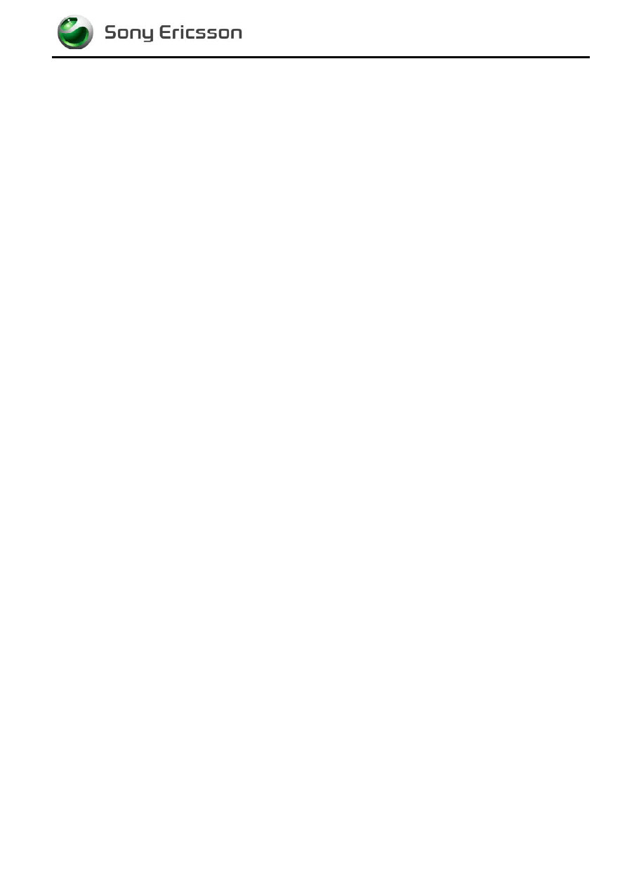
1
Fig. 1.1
Release the battery and
remove it. (Fig. 1.1)
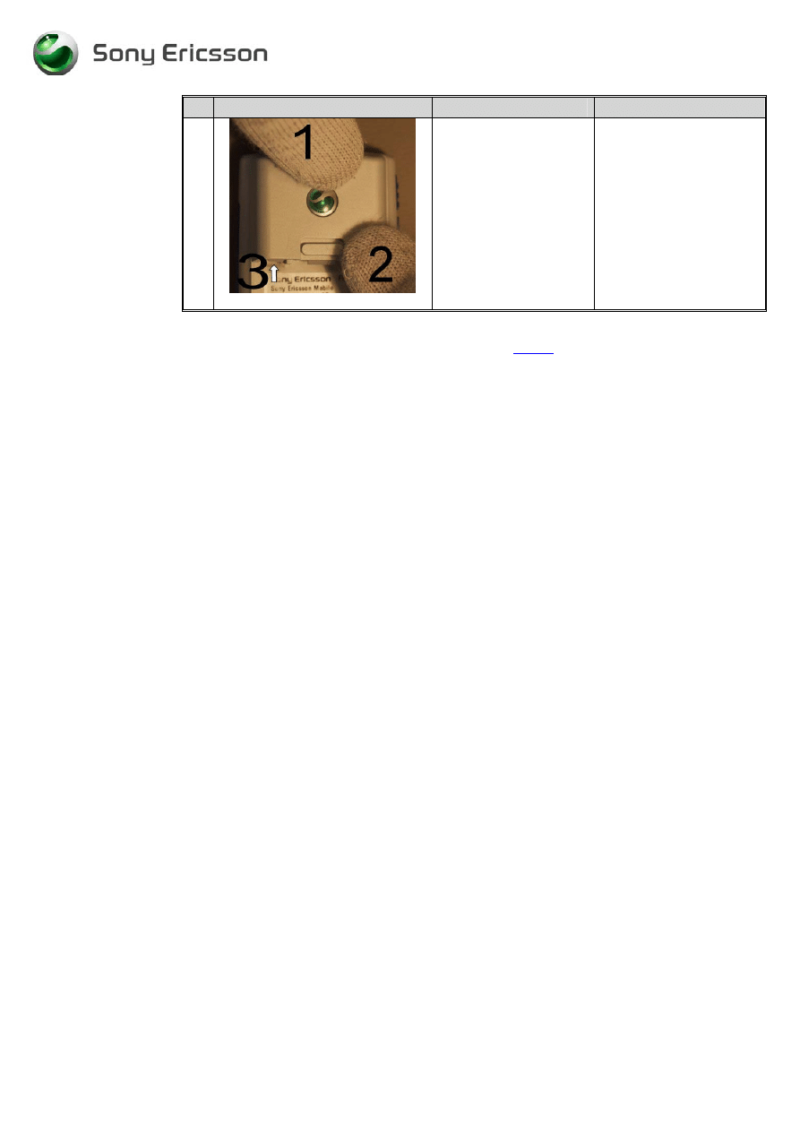
2
Fig. 1.2
Use the antenna cover
opener NTZ 112 504 to
remove the antenna
cover. (Fig. 1.2) Place it
under the snap hooks.
Be careful so you don’t
scratch the antenna cover
or the rear cover.
Working Instructions, SP/Mechanical
3_00021-1/FEA 209 544/78 C
Sony Ericsson Mobile Communications AB
3(23)
# Figure
Instruction
Note
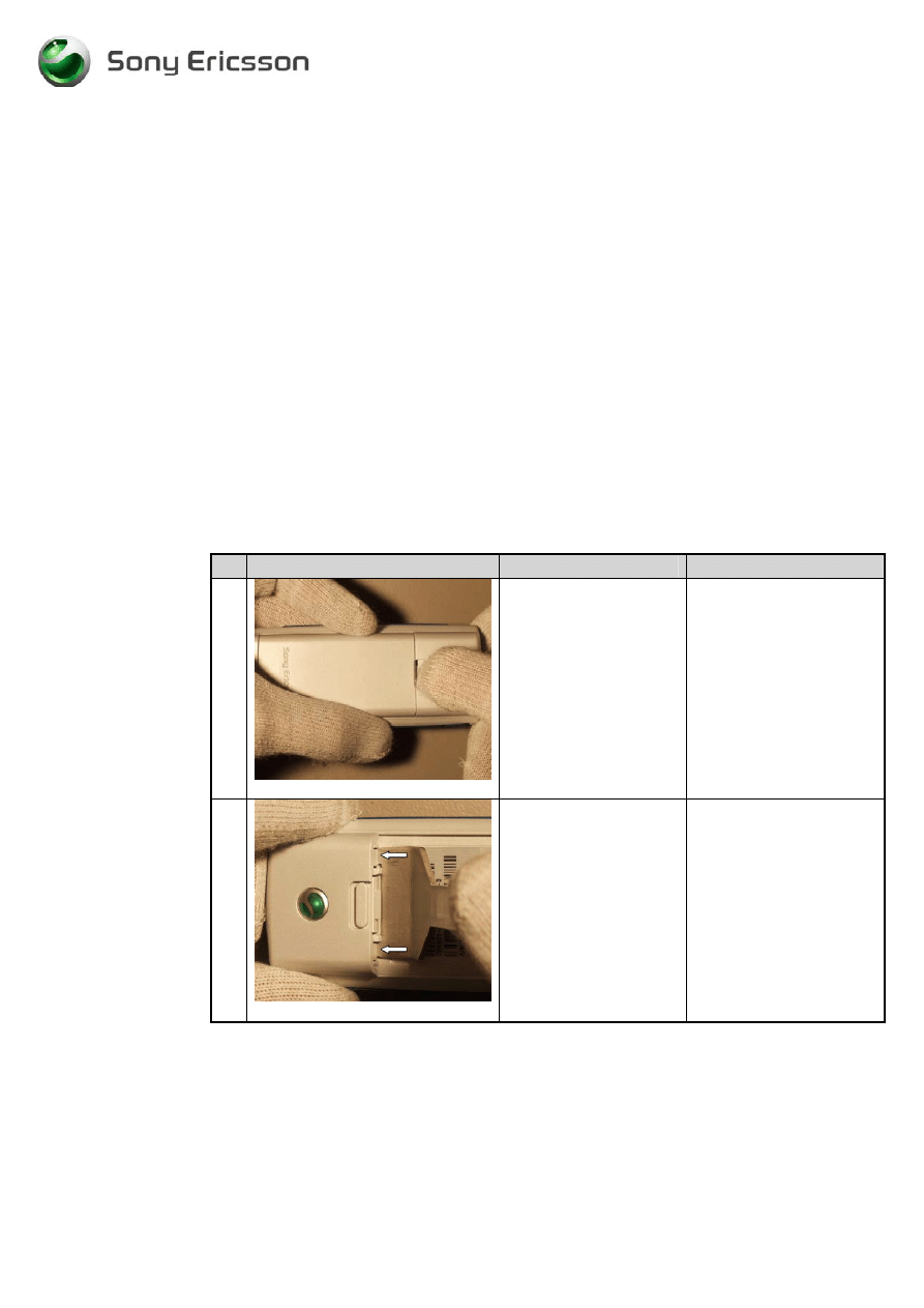
3
Fig. 1.3
Press down the tool until
the antenna cover
releases from the rear
cover. (Fig. 1.3)
You may need to use
some force. The tips at the
Antenna opening tool
must be pushed as far as
possible between the
antenna cover and the rear
cover.
4
Fig. 1.4
Remove the 4 screws.
(Fig. 1.4)
5
Fig. 1.5
Use the Top opening
tool to release the Rear
cover from the Front
cover. Place the tool
between the Rear cover
and the Front cover.
(Fig. 1.5)
Place the Top opening
tool as shown at the
picture.
Do not use a screwdriver
or other sharp tools; it
might cause some damage
to the plastics or other
components.
6
Fig. 1.6
Remove the volume key
with help of a pair of
tweezers. (Fig. 1.6)
Release the Volume key
from the front cover, by
lifting if straight up.
Working Instructions, SP/Mechanical
3_00021-1/FEA 209 544/78 C
Sony Ericsson Mobile Communications AB
4(23)
# Figure
Instruction
Note
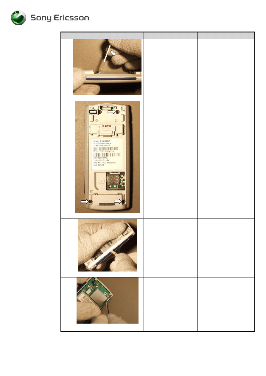
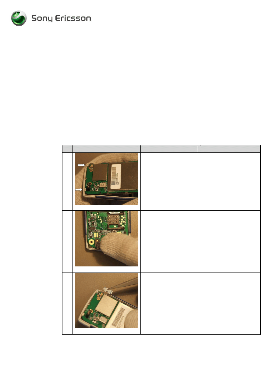
7
Fig. 1.7
There are 3 hooks
holding the PCB into the
front cover. 2 in the top
and 1 in the lower left
corner. (Fig. 1.7)
8
Fig. 1.8
Use a Top opening tool
to release the lower left
hook.
(Fig. 1.8 & Fig. 19)
Note! There is a risk of
damaging the PCB or the
front cover if you are not
using the Top opening
tool.
9
Fig. 1.9
When Top opening tool
is placed in the right
position (as in the
picture) Release the
PCB from the front
cover hook by pushing
the Top opening tool
downwards.
10
Fig. 2.0
Lift the PCB up by grab
hold of the system
connector with your
fingers.
(Fig. 2.0)
Working Instructions, SP/Mechanical
3_00021-1/FEA 209 544/78 C
Sony Ericsson Mobile Communications AB
5(23)
2 Reassembly
2.1 Process
Tools
•
Torque screwdriver, torx no.6 set to 15 Ncm.
•
Pair of tweezers
2.2 Equipment
•
ESD-gloves (cotton gloves)
•
ESD-wristband
2.3 Instructions
# Figure
Instruction
Note
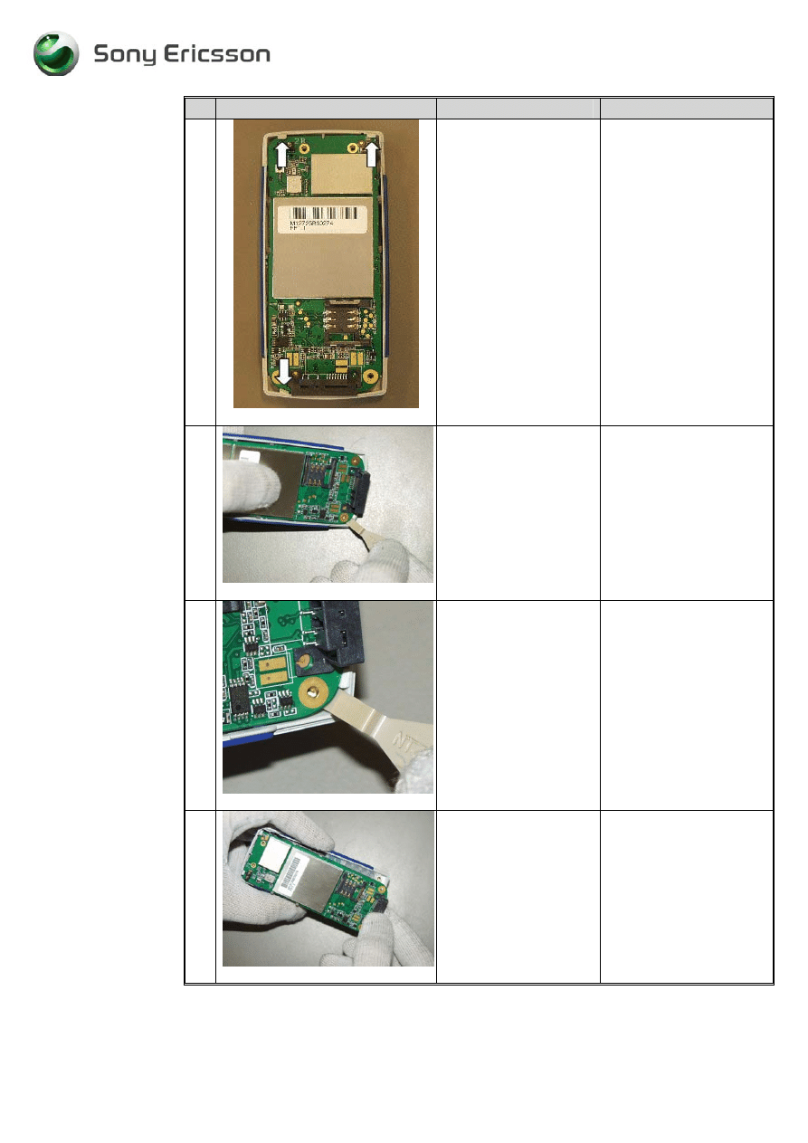
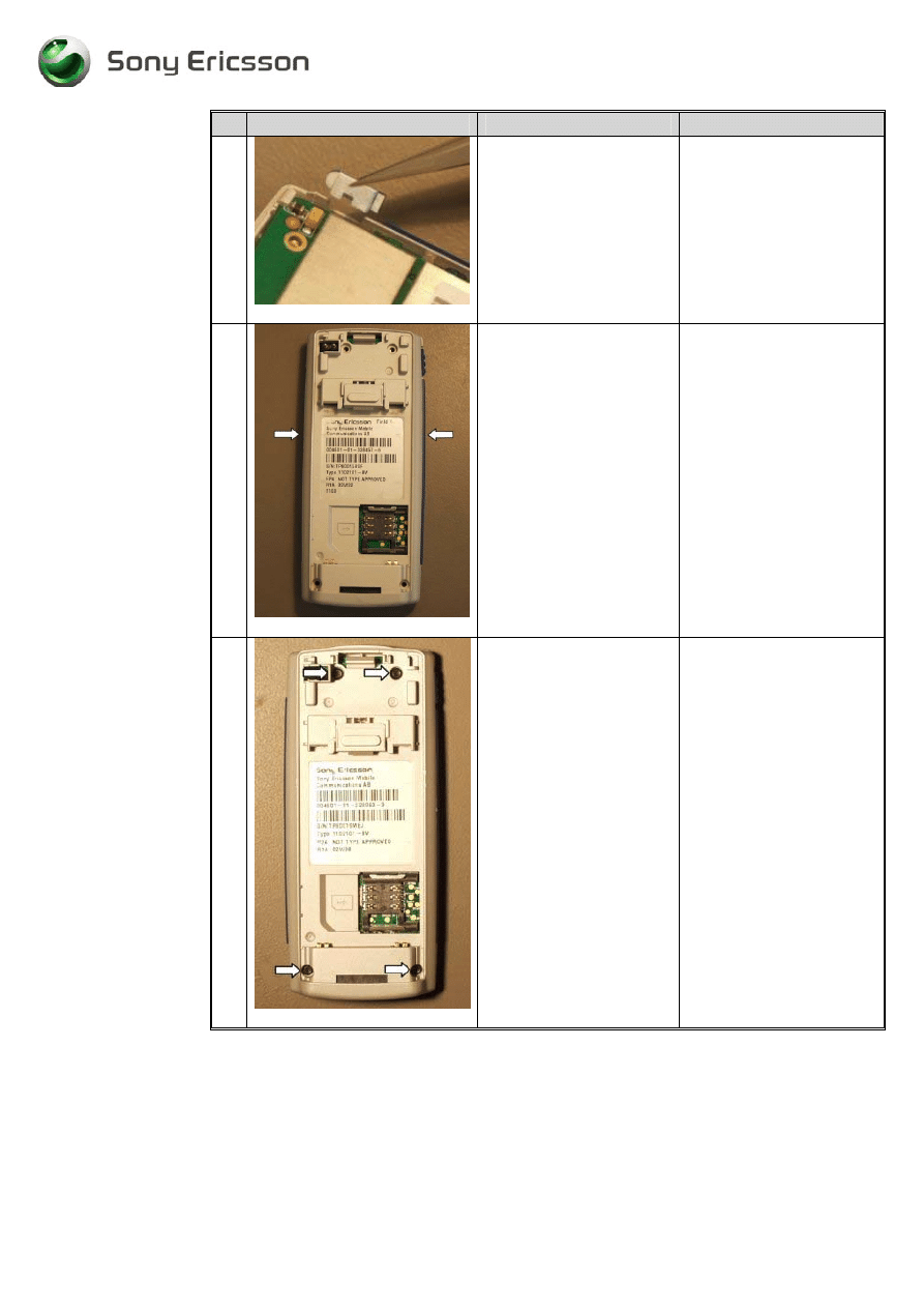
1
Fig. 2.1
Place the PCB under the 2
hooks in the top. (Fig. 2.1)
2
Fig. 2.2
Press on the system
connector to make the
PCB fit tightly to the front
cover. (Fig. 2.2)
3
Fig. 2.3
Mount the volume key
with a pair of tweezers.
(Fig. 2.3 & Fig. 2.4)
Position the volume key as
shown on the pictures.
Working Instructions, SP/Mechanical
3_00021-1/FEA 209 544/78 C
Sony Ericsson Mobile Communications AB
6(23)
# Figure
Instruction
Note
4
Fig. 2.4
Make sure that the hole on
the volume key is position
according to the volume
switch on the PCB.
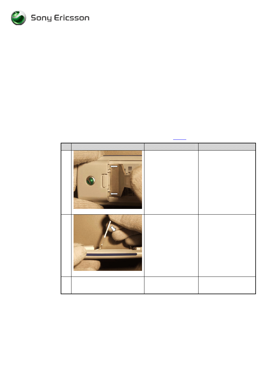
5
Fig. 2.5
Mount Rear Cover into the
Front cover. Start with the
top and press on each side
of it with your fingers to it
fit tightly. (Fig. 2.5)
Arrows indicate where to
press.
6
Fig. 2.6
Tighten the 4 screws.
(Fig. 2.6)
Use a torque screwdriver
torx no. 6 set to 15 Ncm.
Working Instructions, SP/Mechanical
3_00021-1/FEA 209 544/78 C
Sony Ericsson Mobile Communications AB
7(23)
# Figure
Instruction
Note
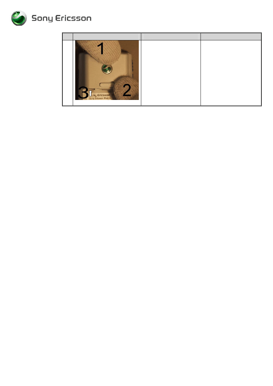
7
Fig. 2.7
Mount the antenna into the
rear cover. Start with the
top (1) simultaneously
press down the 2 snap
hooks (2 & 3)
(Fig. 2.7)
Working Instructions, SP/Mechanical
3_00021-1/FEA 209 544/78 C
Sony Ericsson Mobile Communications AB
8(23)
3 Replacement of Mechanical Parts
3.1 Front
Cover
3.1.1 Process
Tools
•
Pair of tweezers
3.1.2 Equipment
•
ESD-gloves (cotton gloves)
•
ESD-wristband
3.1.3 Instructions
•
Disassemble the phone as described in 1 Disassembly (
page 2-4
), follow steps 1-10
# Figure
Instruction
Note
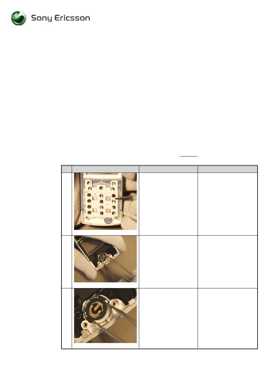
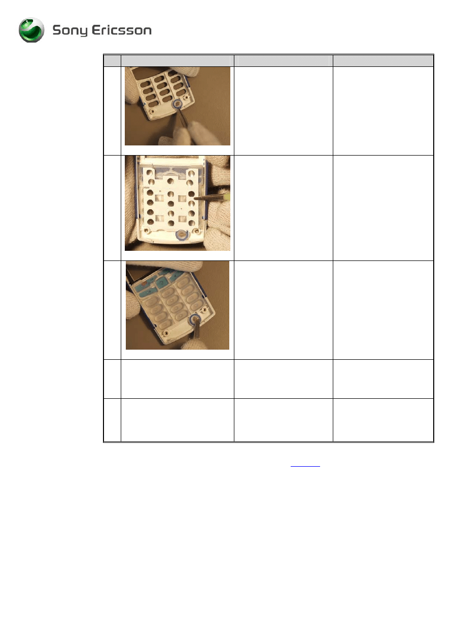
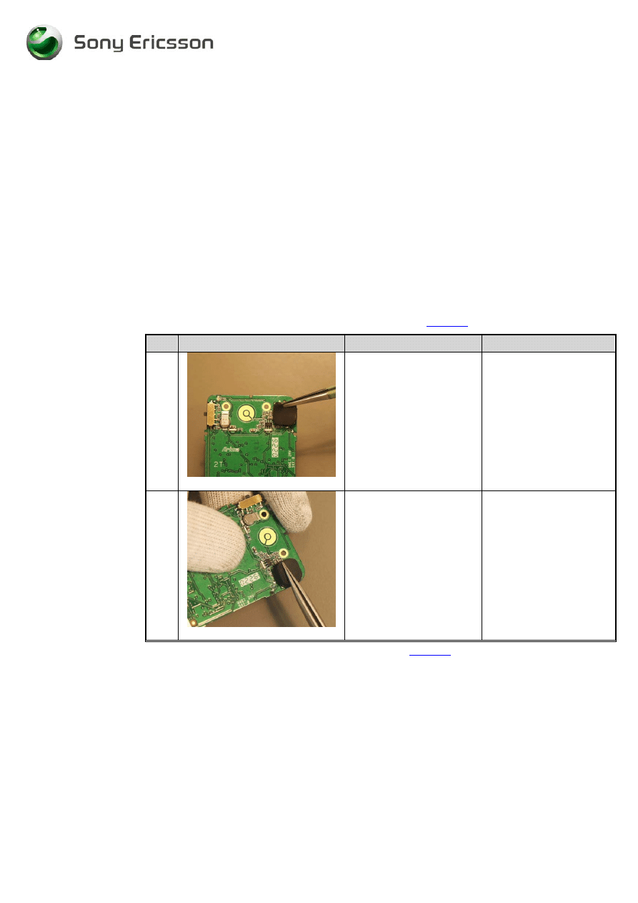
1
Fig. 3.1.1
Remove the keypad, with
a pair of tweezers.
(Fig. 3.1.1)
Do not touch the dome.
2
Fig. 3.1.2
Remove the speaker with
a pair of tweezers.
(Fig. 3.1.2)
Never reuse removed
speaker due to conductivity
problems.
3
Fig. 3.1.3
Press the tips of the
tweezers in the slit, on
each side of the speaker,
and then lift. (Fig. 3.1.3)
Do not lift in the
connectors they are easy to
damage.
Working Instructions, SP/Mechanical
3_00021-1/FEA 209 544/78 C
Sony Ericsson Mobile Communications AB
9(23)
# Figure
Instruction
Note
4
Fig. 3.1.4
To remove the
microphone. Press the
microphone upwards from
the front cover with help
of a pair of tweezers. Press
on the rubber sides until
the microphone is released
from the cavity.
(Fig. 3.1.4)
5
Fig. 3.1.5
Take a new front cover
and place the keypad
inside the front cover with
the help of a pair of
tweezers. (Fig. 3.1.5)
Do not touch the dome.
6
Fig. 3.1.6
Pick up the microphone
with the help of a pair of
tweezers and place it in
the front. (Fig. 3.1.6)
Press on the microphone
until it reaches the bottom
of the cavity. Use gloves
so you don’t contaminate
the elastomer.
7
Remove the foil from the
speaker and place it with
the contacts facing
upwards.
8
Remove the protection
gasket inside the window.
Be careful not to scratch
the inside of the front
window with the pair of
tweezers.
•
Assemble the phone as described in 2 Reassembly (
page 5-6
), follow steps 1-7
Working Instructions, SP/Mechanical
3_00021-1/FEA 209 544/78 C
Sony Ericsson Mobile Communications AB
10(23)
3.2 Microphone
3.2.1 Process
Tools
•
Pair of tweezers
3.2.2 Equipment
•
ESD-gloves (cotton gloves)
•
ESD-wristband
3.2.3 Instructions
•
Disassemble the phone as described in 1 Disassembly (
page 2-4
), follow steps 1-10
# Figure
Instruction
Note
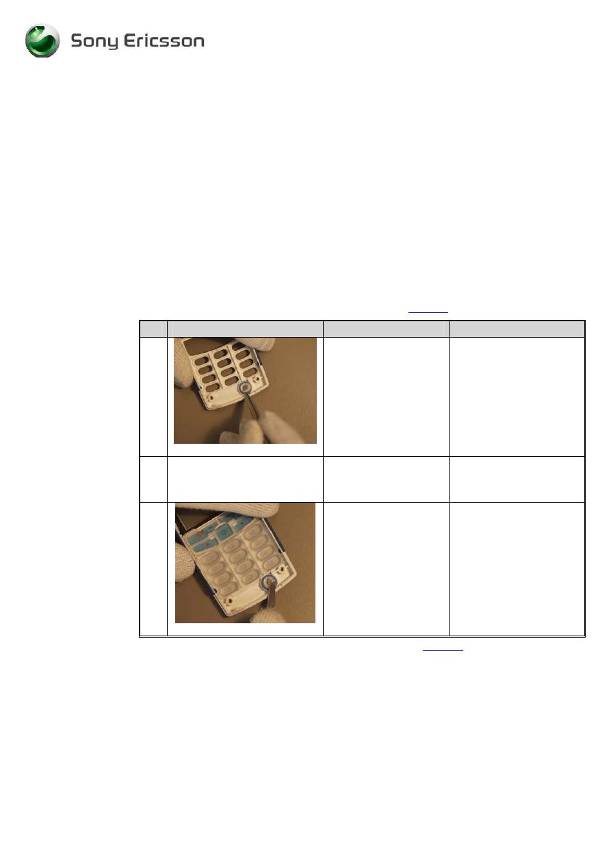
1
Fig. 3.2.1
Remove the microphone
from the cavity on the
front cover with a pair of
tweezers. (Fig. 3.2.1.)
2
Pick up the new
microphone with a pair
of tweezers.
3
Fig. 3.2.2
Mount the microphone
in the cavity in the front
cover. Press the
microphone to it reach
the bottom of the cavity.
(Fig. 3.2.2)
Use gloves, if the
elastomer will be
contaminated, it can result
in connection problems.
•
Assemble the phone as described in 2 Reassembly (
page 5-6
), follow steps 1-7
Working Instructions, SP/Mechanical
3_00021-1/FEA 209 544/78 C
Sony Ericsson Mobile Communications AB
11(23)
3.3 Battery
connectors
3.3.1 Process
Tools
•
Pair of tweezers
3.3.2 Equipment
•
ESD-gloves (cotton gloves)
•
ESD-wristband
3.3.3
Instructions
•
Disassemble the phone as described in 1 Disassembly (
page 2-4
), follow steps 1-5
#
Figure
Instruction
Note
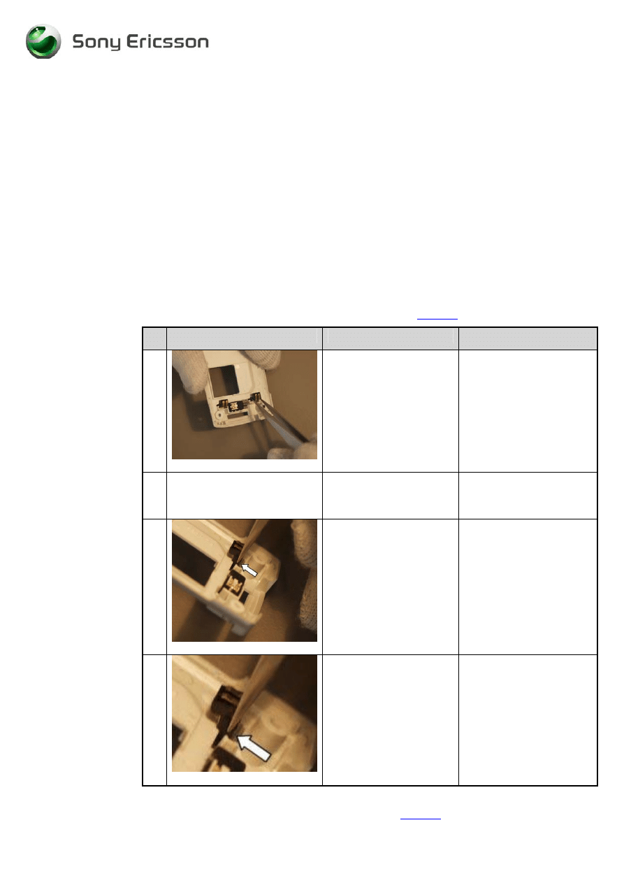
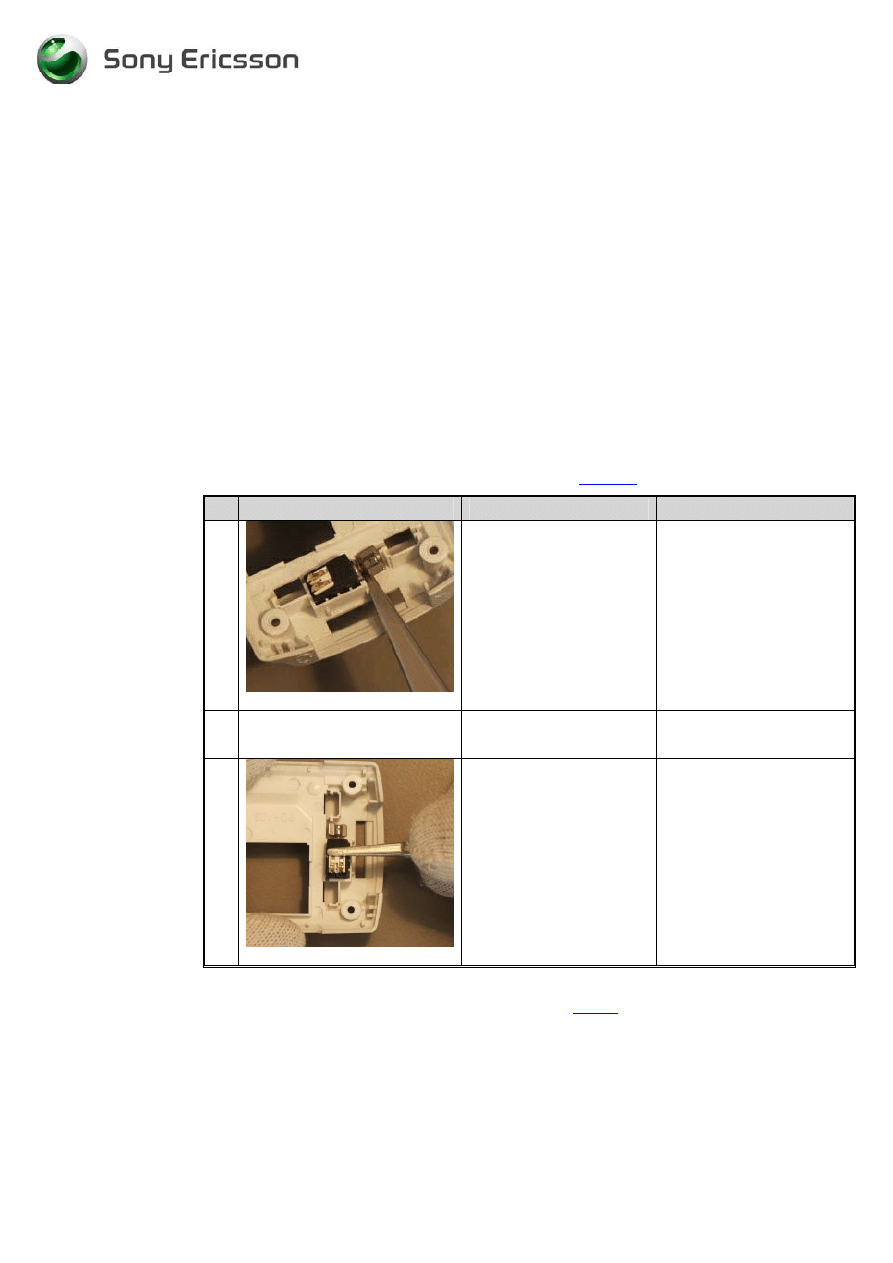
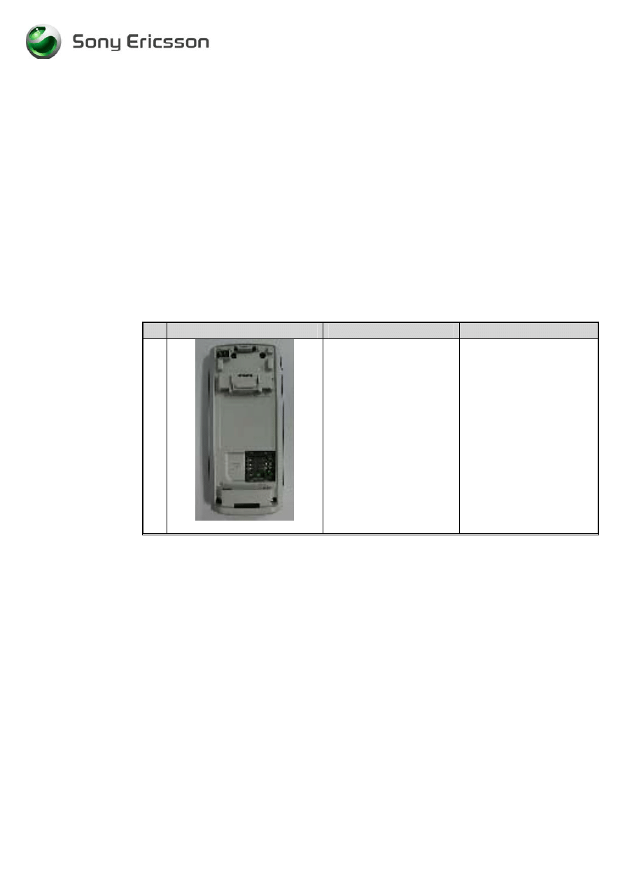
1
Fig. 3.3.1
Use a pair of tweezers to
remove the battery
connectors. (Fig. 3.3.1)
2
Pick up a new battery
connector with a pair of
tweezers.
Make sure that the
connector not is bend or
damage in any way.
3
Fig. 3.3.2
Pick up a battery
connector with the help of
a pair of tweezers and
mount it into the hole in
the rear cover. Repeat this
step with the other battery
connector.
(Fig. 3.3.2 & Fig. 3.3.3)
Make sure that the battery
connector is fitting correct
and that it is not damage in
any way. If the connector
is bend or it does not fit
correctly, replace it.
4
Fig. 3.3.3
•
Assemble the phone as described in 2 Reassembly (
page 5-6
), follow steps 1-7
Working Instructions, SP/Mechanical
3_00021-1/FEA 209 544/78 C
Sony Ericsson Mobile Communications AB
12(23)
3.4 Speaker
3.4.1 Process
Tools
•
Pair of tweezers
3.4.2 Equipment
•
ESD-gloves (cotton gloves)
•
ESD-wristband
3.4.3 Instructions
•
Disassemble the phone as described in 1 Disassembly (
page 2-4
), follow steps 1-10
# Figure
Instruction
Note
1
Fig. 3.4.1
Remove the speaker with
a pair of tweezers.
(Fig. 3.4.1)
Never reuse removed
speaker due to conductivity
problems.
2
Fig. 3.4.2
Press the tops of the
tweezers into the slit on
the speaker, then lift.
(Fig. 3.4.2)
Do not lift in the
connectors; be careful they
are easy to damage.
3
Pick up a new speaker
with a pair of tweezers.
4
Remove the protection
foil on the new speaker
with a pair of tweezers.
5
Mount the speaker in the
cavity with the contacts
facing upwards.
•
Assemble the phone as described in 2 Reassembly (
page 5-6
), follow steps 1-7
Working Instructions, SP/Mechanical
3_00021-1/FEA 209 544/78 C
Sony Ericsson Mobile Communications AB
13(23)
3.5 Keypad
3.5.1 Equipment
•
ESD-gloves (cotton gloves)
•
ESD-wristband
3.5.2 Instruction
•
Disassemble the phone as described in 1 Disassembly (
page 2-4
), follow steps 1-7
# Figure
Instruction
Note
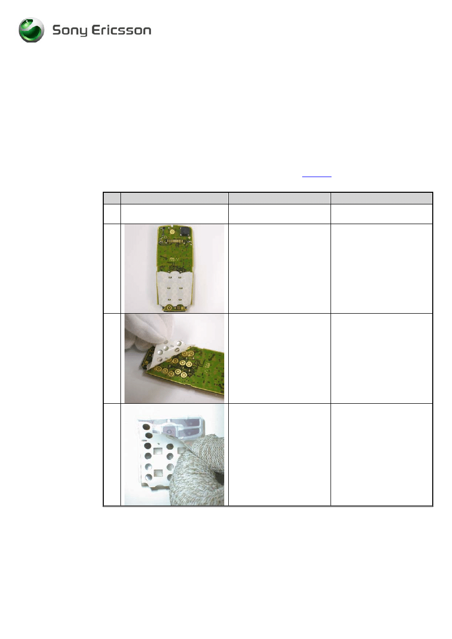
1
Remove the old keypad
Remove dust and dirt with
air blower.
2
In case of glued domefoil,
the foil stays on the PCB
after the removal of the
keypad.
This is the new domefoil
solution with a glued
domefoil on the PCB.
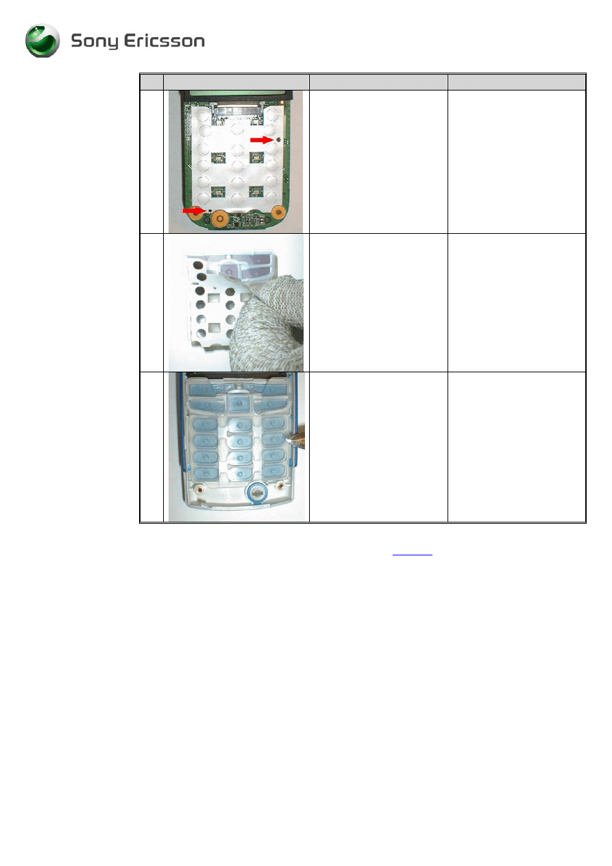
3a
Remove the foil and clean
the surface of the PCB from
glue/dirt.
This is the new domefoil
solution with a glued
domefoil on the PCB.
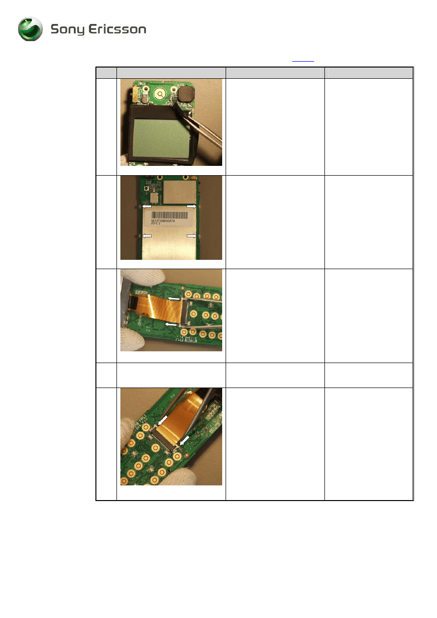
3b
Remove the domefoil from
the keypad.
This is the old domefoil
solution with a glued
domefoil on the keypad
(the surface of the keydome
is NOT adhesive!).
Working Instructions, SP/Mechanical
3_00021-1/FEA 209 544/78 C
Sony Ericsson Mobile Communications AB
14(23)
# Figure
Instruction
Note
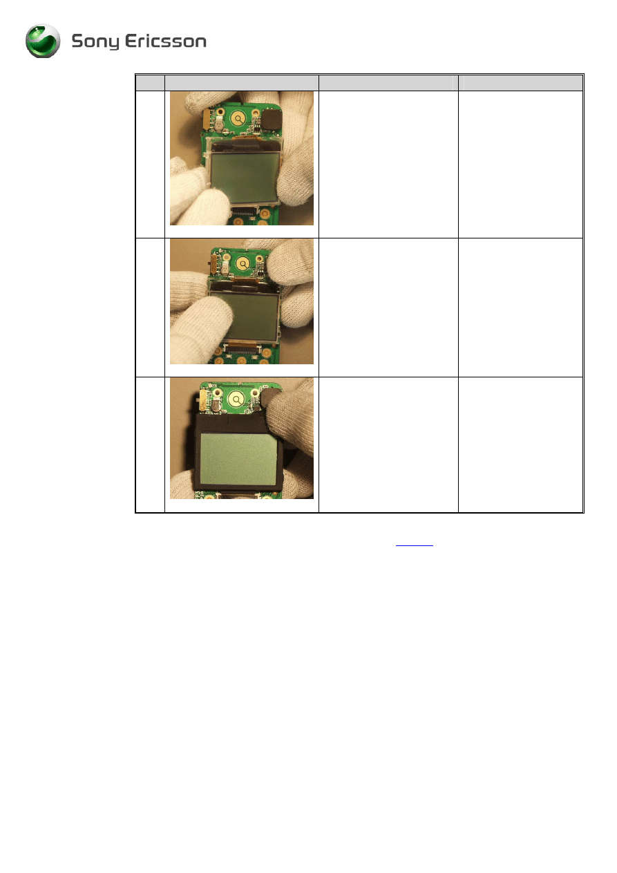
4
Place the new domefoil at
designated place at the PCB
using the two holes as
guidance making sure the
dome gets the right
position.
Do not touch the domes.
5
Pick up a new keypad (use
the old keypad if not
damaged. Fig.3b) with a
pair of tweezers. Remove
the domefoil.
6
Place the new keypad into
the front cover.
Do NOT forget to
REMOVE the domefoil
attached to the keypad.
•
Assemble the phone as described in 2 Reassembly (
page 5-6
), follow steps 1-7
3.6 Display
assembly
3.6.1 Process
Tools
•
Pair of tweezers
3.6.2 Equipment
•
ESD-gloves (cotton gloves)
•
ESD-wristband
3.6.3 Instructions
Working Instructions, SP/Mechanical
3_00021-1/FEA 209 544/78 C
Sony Ericsson Mobile Communications AB
15(23)
•
Disassemble the phone as described in 1 Disassembly (
page 2
), follow steps 1-10
#
Figure
Instruction
Note
1
(Fig. 3.6.1)
Remove the LCD gasket
with a pair of tweezers.
(Fig. 3.6.1)
Be careful so you don’t
damage the LCD gasket
or the LCD assy.
2
Fig. 3.6.2
Use your fingers to release
the hooks for the LCD, by
pushing them outwards
from the PCB. Start with
the 2 hooks at the right or
the left side.
(Fig. 3.6.2)
3
Fig. 3.6.3
Release the LCD contact by
pulling the ZIF-connector
lock upwards. Remove the
LCD flex film. (Fig. 3.6.3)
Be careful so you don’t
damage the LCD flex
film.
4
Pick up a new LCD
Avoid any contact with
all surfaces. Use gloves!
5
Fig. 3.6.4
Mount the LCD flex film in
the LCD contact with your
fingers. Close the ZIF-
connector with a pair of
tweezers as shown at the
picture. (Fig. 3.6.4)
Be careful so you don’t
harm the LCD flex film.
Working Instructions, SP/Mechanical
3_00021-1/FEA 209 544/78 C
Sony Ericsson Mobile Communications AB
16(23)
#
Figure
Instruction
Note
6
Fig. 2.6.5
Place the LCD assy in the
right side of the PCB; make
sure the hooks are on the
correctly side at the PCB.
The hooks should be
mounted on the opposite
side of the PCB as the LCD
assy. (Fig. 2.6.5)
The guiding pins on the
LCD assy shall fit into
the holes on the PCB.
7
Fig. 2.6.6
Press very gently at the left
side on the LCD.
(Fig. 2.6.6)
Be careful so you don’t
damage the LCD assy.
Use gloves.
Remember to remove
the LCD protection film.
8
Fig. 2.6.7
Mount the LCD gasket on
the LCD assy.
(Fig. 2.6.7)
Be careful so you don’t
damage the LCD assy or
LCD gasket. Use
gloves.
•
Assemble the phone as described in 2 Reassembly (
page5-6
), follow steps 1-7
Working Instructions, SP/Mechanical
3_00021-1/FEA 209 544/78 C
Sony Ericsson Mobile Communications AB
17(23)
3.7 Buzzer protection rubber
3.7.1 Process
tools
•
Pair of tweezers
3.7.2 Equipment
•
ESD-gloves (cotton gloves)
•
ESD-wristband
3.7.3 Instructions
•
Disassemble the phone as described in 1 Disassembly (
page 2-4
), follow steps 1-10
#
Figure
Instruction
Note
1
Fig. 3.7.1
Remove the buzzer
protection rubber; grab it
in the corner with a pair
of tweezers.
(Fig. 3.7.1)
2
Fig. 3.7.2
Pick up a new buzzer
protection rubber. Mount
the buzzer protection
rubber by pressing it on
the buzzer until it fits
correctly. (Fig. 3.7.2)
It has to be mounted with
the exit hole to the right.
Make sure that the exit
on the Buzzer protection
rubber is free from dust
and dirt.
•
Assemble the phone as described in 2 Reassembly (
page 5-6
), follow steps 1-7
Working Instructions, SP/Mechanical
3_00021-1/FEA 209 544/78 C
Sony Ericsson Mobile Communications AB
18(23)
3.8 Volume
key
3.8.1 Process
Tool
•
Pair of tweezers
3.8.2 Equipment
•
ESD-gloves (cotton gloves)
•
ESD-wristband
3.8.3 Instructions
•
Disassemble the phone as described in 1 Disassembly (
page 2-3
), follow steps 1-6
# Figure
Instruction
Note
1
Pick up a new volume key
with a pair of tweezers.
•
Assemble the phone as described in 2 Reassembly (
page 5-6
), follow steps 3-7
Working Instructions, SP/Mechanical
3_00021-1/FEA 209 544/78 C
Sony Ericsson Mobile Communications AB
19(23)
3.9 Vibrator
Assembly
3.9.1 Process
Tools
•
Pair of tweezers
3.9.2 Equipment
•
ESD-gloves (cotton gloves)
•
ESD-wristband
3.9.3 Instructions
•
Dismount the phone as described in 1 Disassembly (
page 2-3
), follow steps 1-5
# Figure
Instruction
Note
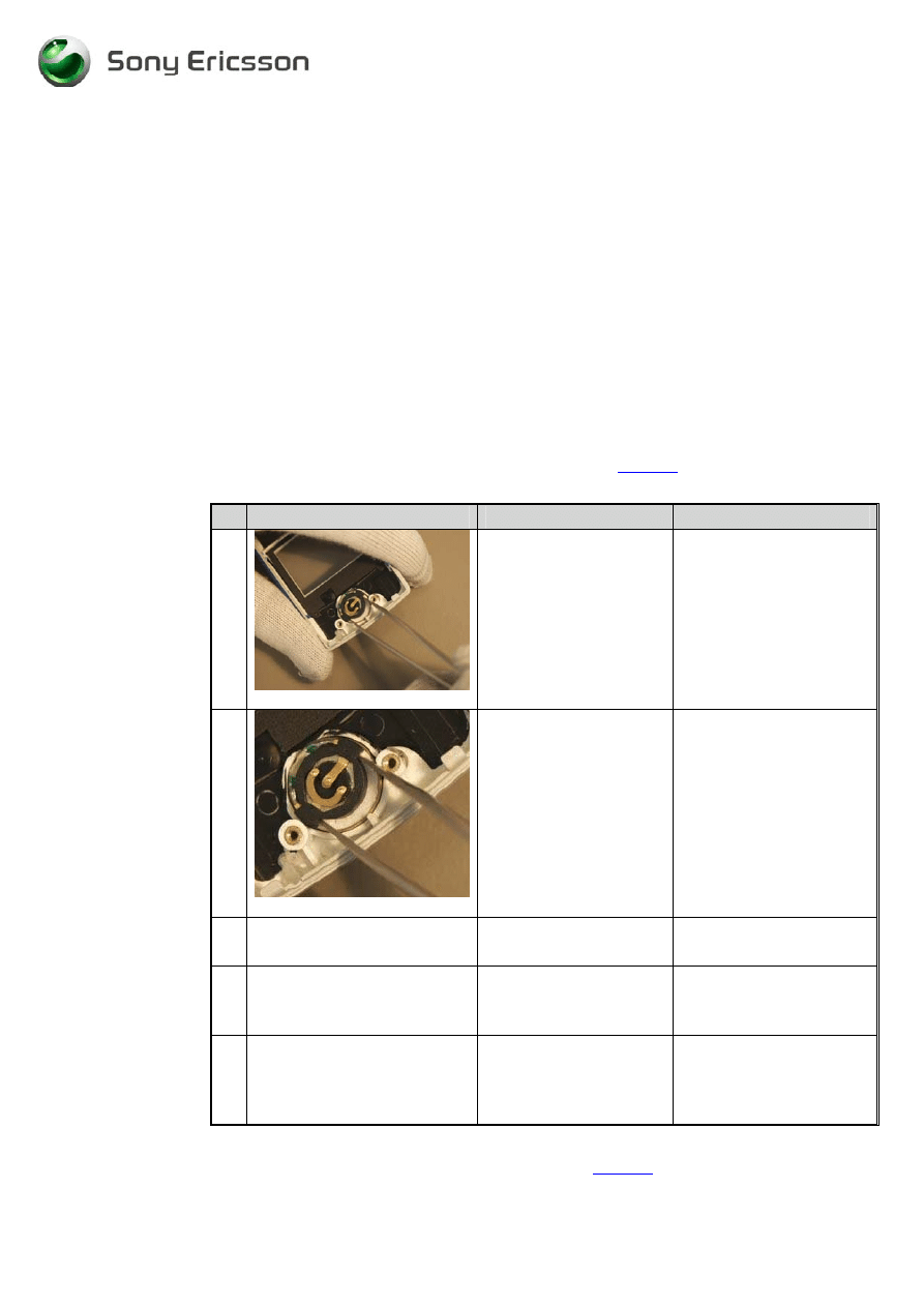
1
Fig. 3.9.1
Remove the vibrator
assembly with a pair of
tweezers by lifting the
vibrator up by the
flywheel. (Fig. 3.9.1)
2
Pick up a new vibrator
assembly.
3
Fig. 3.9.2
Pick up the vibrator with
the help of a pair of
tweezers and position it in
cavity of the rear cover.
(Fig. 3.9.2)
Press exactly as shown at
the picture. Press the
vibrator until it reaches the
bottom of the cavity. Do
not press on the flywheel,
it can cause damage on the
vibrator.
•
Assemble the phone as described in 2 Reassembly (
page 6
), follow steps 5-7
Working Instructions, SP/Mechanical
3_00021-1/FEA 209 544/78 C
Sony Ericsson Mobile Communications AB
20(23)
3.10 Antenna Cover Replacement
3.10.1 Process Tools
•
Antenna Cover Opener NTZ 112 504
3.10.2 Equipment
•
ESD-gloves (cotton gloves)
•
ESD-wristband
3.10.3 Instructions
•
Dismount the phone as described in 1 Disassembly (
page 2
), follow steps 1-3
# Figure
Instruction
Note
1
Fig. 3.10.1
Use the antenna cover
opener NTZ 112 504 to
remove the antenna
cover. (Fig. 3.10.1)
Place it under the snap
hooks.
Be careful so you don’t
scratch the antenna cover
or the rear cover.
2
Fig. 3.10.2
Press down on the tool
until the antenna cover
releases from the rear
cover. (Fig. 3.10.2)
You may need to use
some force. The tips at the
Antenna opening tool
must be pushed as far as
possible between the
antenna cover and the rear
cover.
2
Pick up a new Antenna
cover assembly.
Working Instructions, SP/Mechanical
3_00021-1/FEA 209 544/78 C
Sony Ericsson Mobile Communications AB
21(23)
# Figure
Instruction
Note
3
Fig. 3.10.3
Mount the antenna into
the rear cover. Start with
the top (1)
simultaneously press
down the 2 snap hooks
(2 & 3). (Fig. 3.10.3)
•
Assemble the phone as described in 2 Reassembly (
page 6
), follow step 14
Working Instructions, SP/Mechanical
3_00021-1/FEA 209 544/78 C
Sony Ericsson Mobile Communications AB
22(23)
4 Process Tools for Label
•
Hot air blower
•
Pair of tweezers
4.1 Instructions
This instruction should be used when you intend to exchange an old label or mount a new
one.
1. Heat up the label with a hot air blower.
2. Carefully remove the label, make sure that all the residue is removed. Do not scratch the
frame.
NOTE!
Only one label is allowed in the battery cavity.
3. Printing: The text must be fully readable visually and through bar code readers.
# Figure
Instruction
Note
1
Fig. 4.1
Take the new label and
place it in the battery
cavity. The label should be
centred and parallel to the
sides of the cavity.
(Fig. 4.1)
Make sure that there are no
air bubbles under the label.
Working Instructions, SP/Mechanical
3_00021-1/FEA 209 544/78 C
Sony Ericsson Mobile Communications AB
23(23)
5 Revision History
Rev. Date
Changes / Comments
A 2002-11-15
First
release
B 2003-02-28
T106
added
C
2003-07-29
T105 & Instruction for PCB-glued domefoil added
Wyszukiwarka
Podobne podstrony:
sony ericsson k770 installation instruction, mechanical
sony ericsson k770 test instruction, mechanical
Sony Ericsson T610 instrukcja rozbiórki
Sony Ericsson GC79, TELEFONIA, Opisy telefonów
sony-ericsson, Analiza finasowa
sony-ericsson, PODSTAWY ZARZĄDZANIA
problemy Sony Ericsson
simlock, Telefony, SONY ERICSSON, C510
Sony Ericsson GC79, TELEFONIA, Opisy telefonów
sony ericsson k770 equipment list, mechanical
Sony Ericsson W910i EN
Sony Ericsson wprowadza dwa nowe modele W508 i C510
sony ericsson k770 part list, mechanical
Jak odzyskać usunięte smsy z telefonu sony ericsson xperia
Jak odzyskać smsy z telefonu sony ericsson
więcej podobnych podstron