
Working Instructions, SP/Mechanical
3/000 21-1/FEA 209 544/76 E
SonyEricsson Mobile Communications AB
Working Instructions, SP/Mechanical
Applicable for T610/T618
1 Disassembly............................................................................................................................2
Process Tools ....................................................................................................................2
Equipment.........................................................................................................................2
Instructions........................................................................................................................2
2
Reassembly ............................................................................................................................8
Process Tools ....................................................................................................................8
Equipment.........................................................................................................................8
Instructions........................................................................................................................8
3 Replacement of Mechanical Parts ......................................................................................15
3.1
Microphone......................................................................................................15
3.2
Vibrator Assembly...........................................................................................16
3.3
SIM-lock lid.....................................................................................................17
3.4
Speaker ............................................................................................................18
3.5
Keyboard .........................................................................................................19
3.6
Volume/Camera Key .......................................................................................20
3.7
Internet Access Key.........................................................................................21
3.8
Sound channel Gasket .....................................................................................22
3.9
Joystick gasket.................................................................................................23
3.10
Antenna assembly............................................................................................24
3.11
Dome Foil assembly ........................................................................................25
3.12
Display assembly.............................................................................................27
3.13
Camera ring and camera ring gasket ...............................................................29
3.14
Front replacement, Light Gasket .....................................................................30
4. Process Tools for Label.......................................................................................................32
4.1
Instructions ......................................................................................................32
5
Revision History ..................................................................................................................32
-
2
-
Working Instructions, SP/Mechanical
3/000 21-1/FEA 209 544/76 E
SonyEricsson Mobile Communications AB
2(32)
1 Disassembly
Process Tools
•
Torque screwdriver, torx no.6 set to 20 Ncm.
•
Blunt Pair of tweezers
•
Antenna Cover Opener NTZ 112 520
•
Flex film Assembly Tool NTZ 112 521
•
Front opening tool NTZ 112 302
•
Camera gasket assembly tool NTZ 112 507
Equipment
•
ESD-gloves (cotton gloves)
•
ESD-wristband
Instructions
# Figure
Instruction
Note
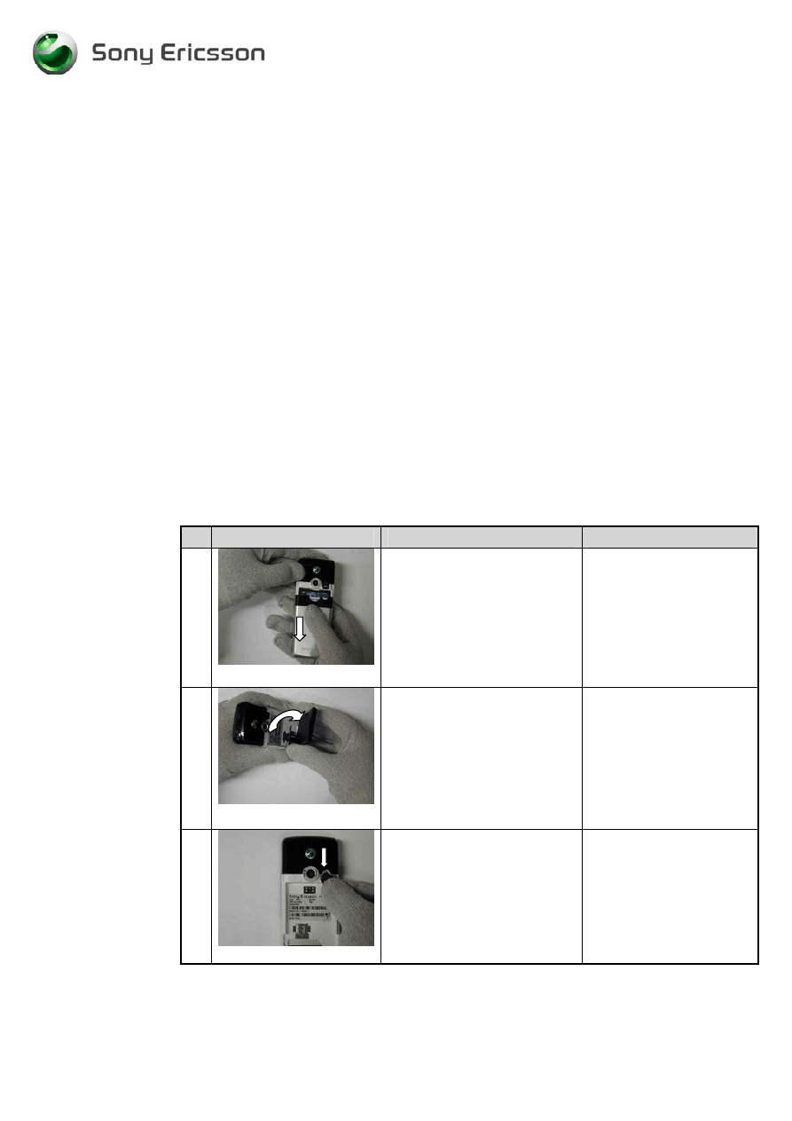
1
fig1.1
Remove the battery cover with
your fingers. Slide the battery
cover down.
(fig1.1)
2
fig1.2
Remove the battery by lifting it
up with your fingers.
(fig1.2)
3
fig1.3
Remove the rubber plug for the
external antenna with a pair of
tweezers.
(fig1.3)
-
3
-
Working Instructions, SP/Mechanical
3/000 21-1/FEA 209 544/76 E
SonyEricsson Mobile Communications AB
3(32)
# Figure
Instruction
Note
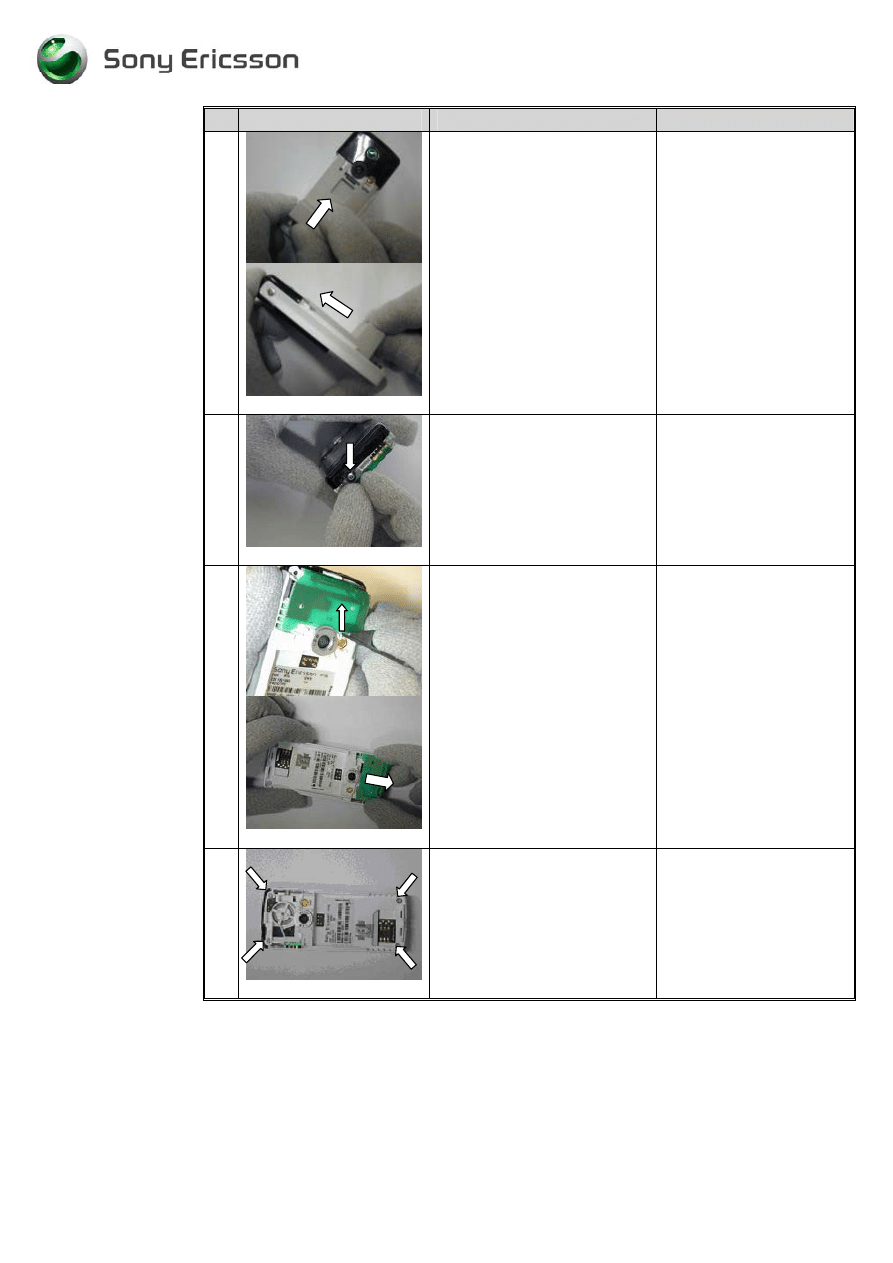
4
fig 1.4
Remove the antenna cover. Use
the Antenna Cover Opening
tool. Push the tool inside the
battery cavity in the arrow
direction until it contacts the
battery cavity wall. The cover
should only be pushed until the
snap lock is released. Then
remove the antenna cover with
your fingers.
( fig 1.4)
Be careful not to damage
the close clips on the
antenna cover with the
antenna cover opening
tool. If you damage it you
must replace the antenna
cover.
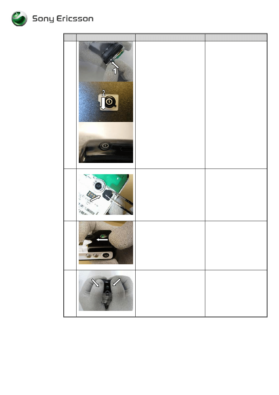
5
fig1.5
Remove the on/off key with
your fingers.
(Fig. 1.5)
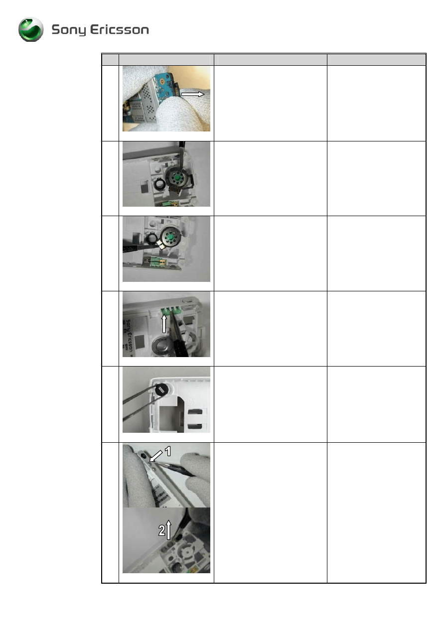
6
fig1.6
Remove the antenna assembly
by using the front opening tool
NTZ 112 302. Release it and
then gently remove it with your
fingers.
(fig1.6)
Gently push the antenna
assembly in the arrow
direction.
7
fig1.7
Remove the 4 screws.
(fig1.7)
Removed screws can not
be reused and must be
scrapped.
-
4
-
Working Instructions, SP/Mechanical
3/000 21-1/FEA 209 544/76 E
SonyEricsson Mobile Communications AB
4(32)
# Figure
Instruction
Note
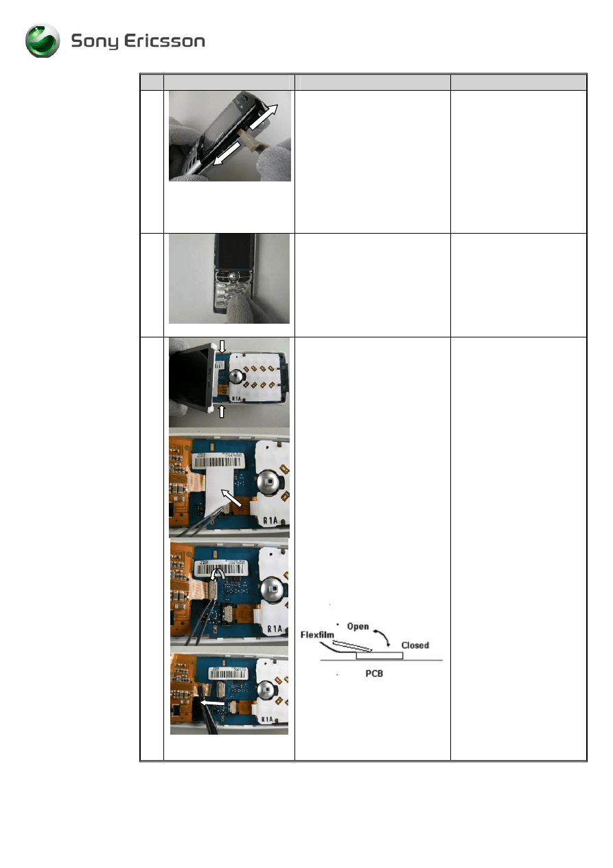
8
fig1.8
Open the phone with the Front
opening tool.
Begin as the picture shows.
If necessary gently move the
tool along the gap both ways
until the latch on the inside is
loose. If necessary do the same
thing at the other side.
(Fig 1.8)
Be careful not to scratch
the phone with the Front
opening tool.
9
fig 1.9
Remove the keyboard with
your fingers.
(fig1.9)
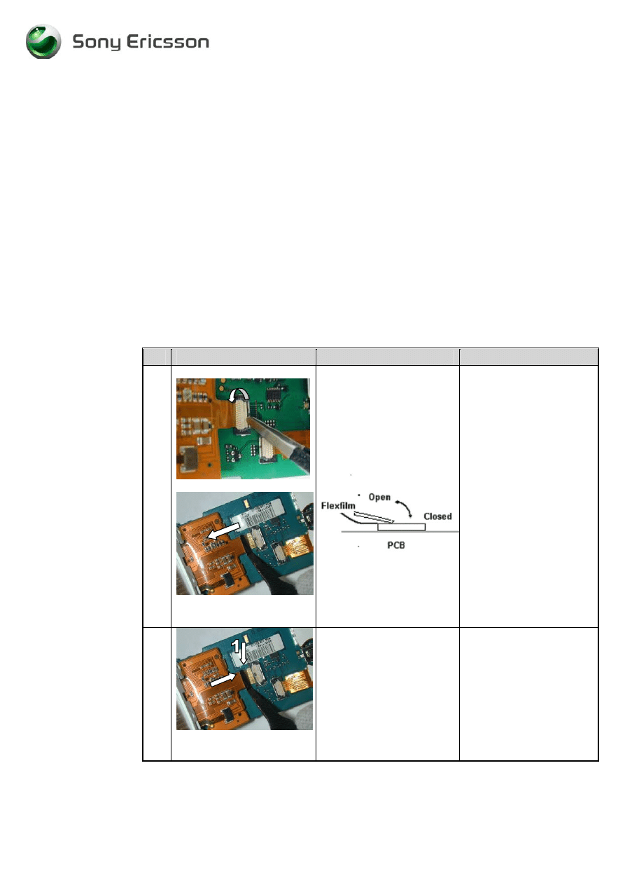
10
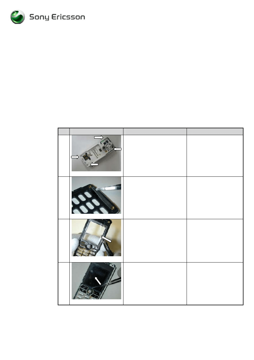
fig 1.10
Lift the display up with your
fingers. You may have to loose
the latches at the arrows.
Remove the ZIF tape with the
help of a pair of tweezers.
Open the ZIF-connector,
connected to the display, with a
pair of tweezers.
Remove the Flex film from the
ZIF-connector with the flex-
film-assembly tool.
(fig 1.10)
Do not touch the display-
glass with your fingers
Be careful not to damage
the ZIF-connector.
.
Use the correct pair of
tweezers !!
-
5
-
Working Instructions, SP/Mechanical
3/000 21-1/FEA 209 544/76 E
SonyEricsson Mobile Communications AB
5(32)
# Figure
Instruction
Note
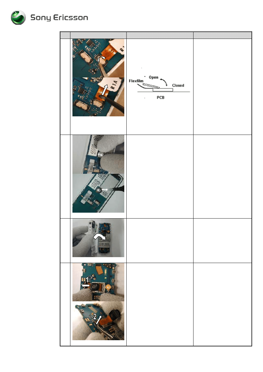
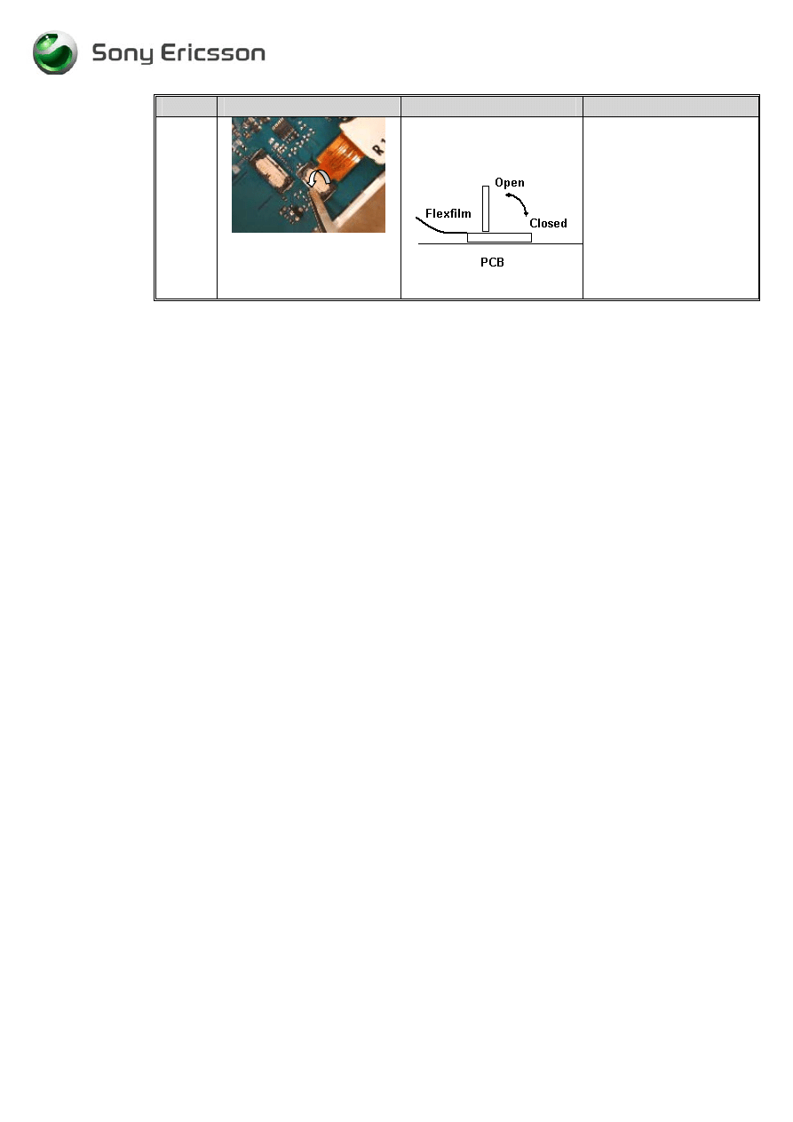
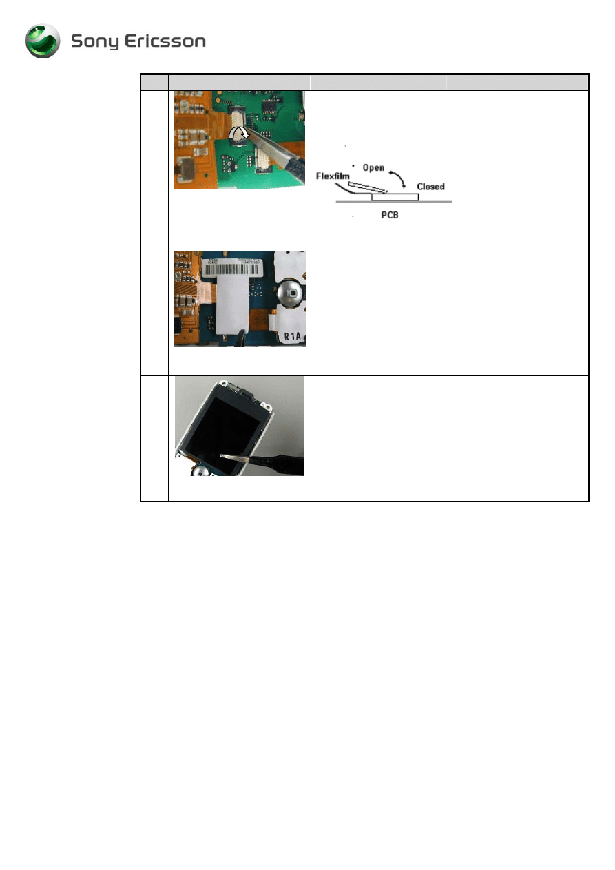
11
fig1.11
Open the ZIF-connector
connected to the dome foil
assembly with a pair of
tweezers.
Remove the Flex film from the
ZIF- connector with the flex
film assembly tool.
( fig1.11)
Be careful not to damage
the ZIF-connector.
Use the correct pair of
tweezers !!
12
fig 1.12
Remove the joystick button
with your fingers.
If necessary use a pair of
tweezers. Put the tweezers
under the joystick button and
press gently upwards.
(fig 1.12)
Be careful not to damage
the button,gasket and PCB
when using a pair of
tweezers.
13
Fig1.13
Release the PCB from the
Frame cavity by overturn the
frame.
(fig 1.13)
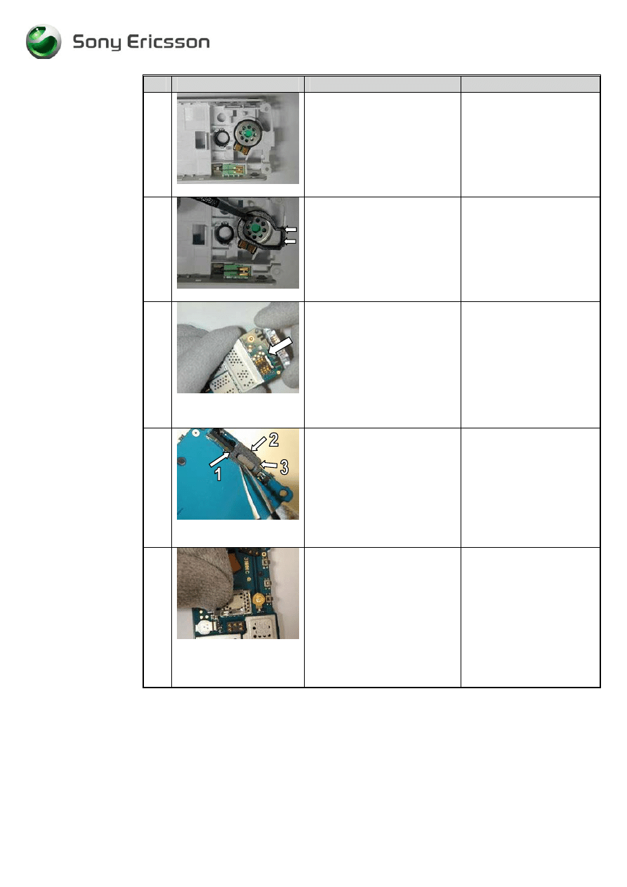
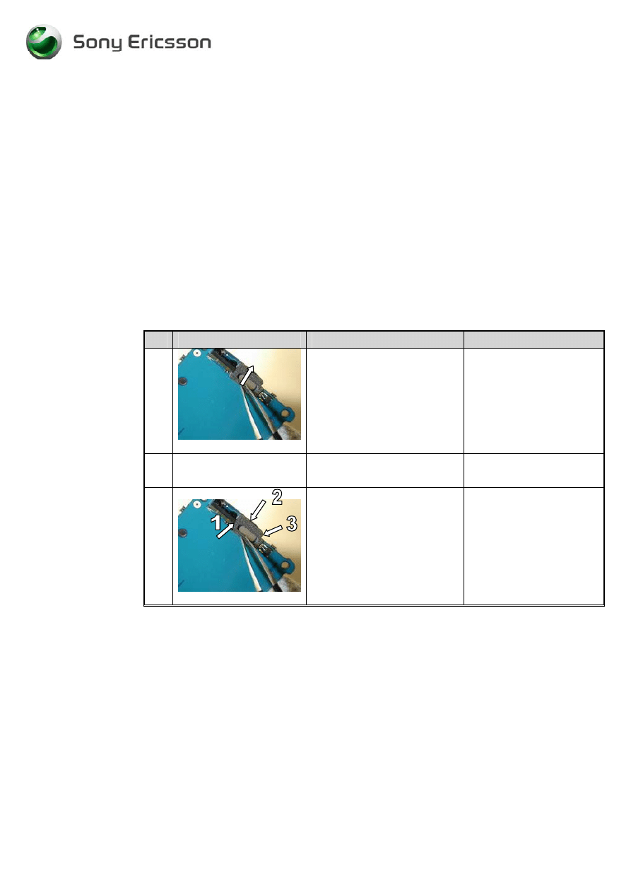
14
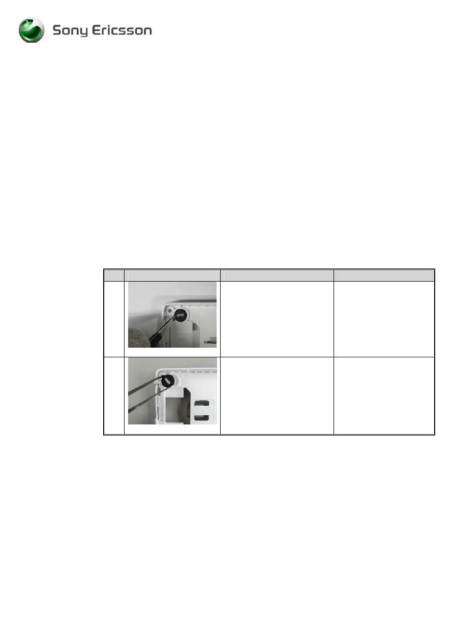
Fig1.14
Remove the camera from the
camera holder by sliding it
gently with your fingers in the
arrow (1) direction.
Lift the camera board to board
connector (2) gently with a pair
of tweezers.
(fig1.14)
Be careful not to damage
the camera holder or
camera flexfilm when
removing the camera.
Be careful not to damage
the components on the
PCB when using the pair
of tweezers.
-
6
-
Working Instructions, SP/Mechanical
3/000 21-1/FEA 209 544/76 E
SonyEricsson Mobile Communications AB
6(32)
# Figure
Instruction
Note
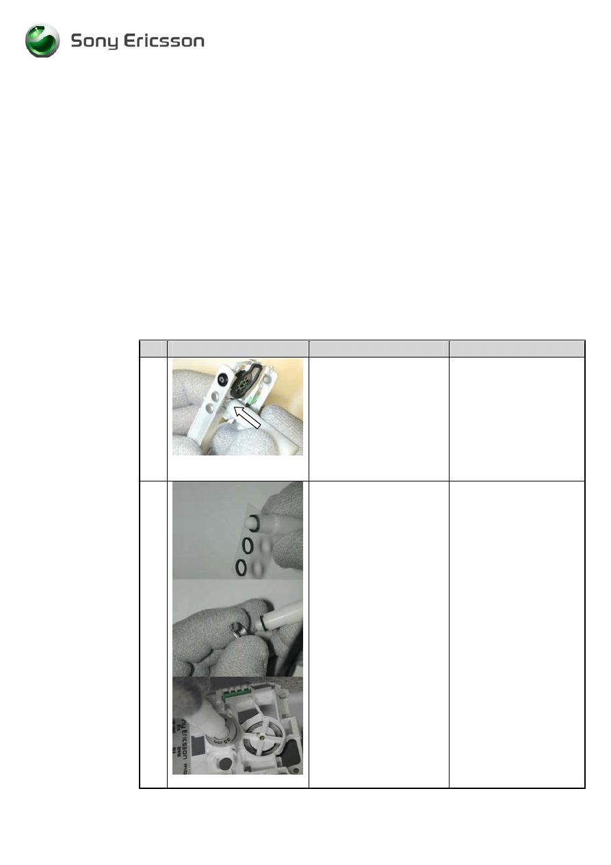
15
Fig 1.15
Remove the system connector
from the board with your
fingers.
(fig 1.15)
16
fig1.16
Remove the speaker gasket.
Use a pair of tweezers.
(fig 1.16)
Removed speaker gasket
can not be reused and must
be scrapped.
Do not touch the contact
pads on the speaker with
your fingers.
17
fig1.17
Pick up the speaker from the
frame cavity with a pair of
tweezers.
(fig 1.17)
Do not touch the contact
pads on the speaker with
your fingers.
18
fig1.18
Remove the vibrator by
pushing it from the rear end of
the frame with a pair
oftweezers.
(fig1.18)
Do not touch or damage
the vibrator contact
springs.
19
fig1.19
Pick up the microphone from
the frame with a pair of
tweezers.
(fig 1.19)
Do not touch the elastomer
with your fingers.
20
fig1.20
Gently push the
Volume/camera key in from
the outside (1) then pick it up
on the inside with a pair of
tweezers.
(fig1.20)
Be gentle !
The rubber can be
damaged when picking it
up (2)
-
7
-
Working Instructions, SP/Mechanical
3/000 21-1/FEA 209 544/76 E
SonyEricsson Mobile Communications AB
7(32)
# Figure
Instruction
Note
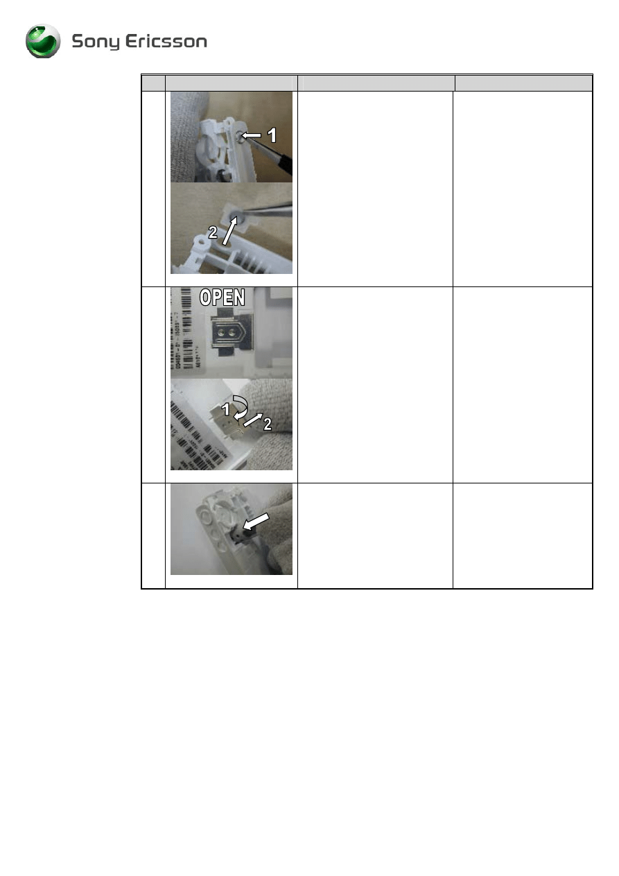
21
fig 1.21
Remove the internet access
key by gently pushing it from
the outside in (1)
Pick up the internet access key
on the inside with a pair of
tweezers.
(fig1.21)
Be gentle !
The rubber can be damaged
when picking it up (2)
22
fig 1.22
Remove the Sim lock lid with
your fingers by first open it..
Lift it up (1) and then pull it
backwards (2).
(fig 1.22)
23
fig 1.23
Remove the camera ring by
pressing it out with the camera
gasket assembly tool.
(fig 1.23)
The camera ring is not to be
reused.
-
8
-
Working Instructions, SP/Mechanical
3/000 21-1/FEA 209 544/76 E
SonyEricsson Mobile Communications AB
8(32)
2 Reassembly
Process Tools
•
Torque screwdriver, torx no.6 set to 20 Ncm.
•
Blunt Pair of tweezers.
•
Flex film Assembly Tool NTZ 112 521
•
Camera gasket assembly tool NTZ 112 507
Equipment
•
ESD-gloves (cotton gloves)
•
ESD-wristband
Instructions
# Figure
Instruction
Note
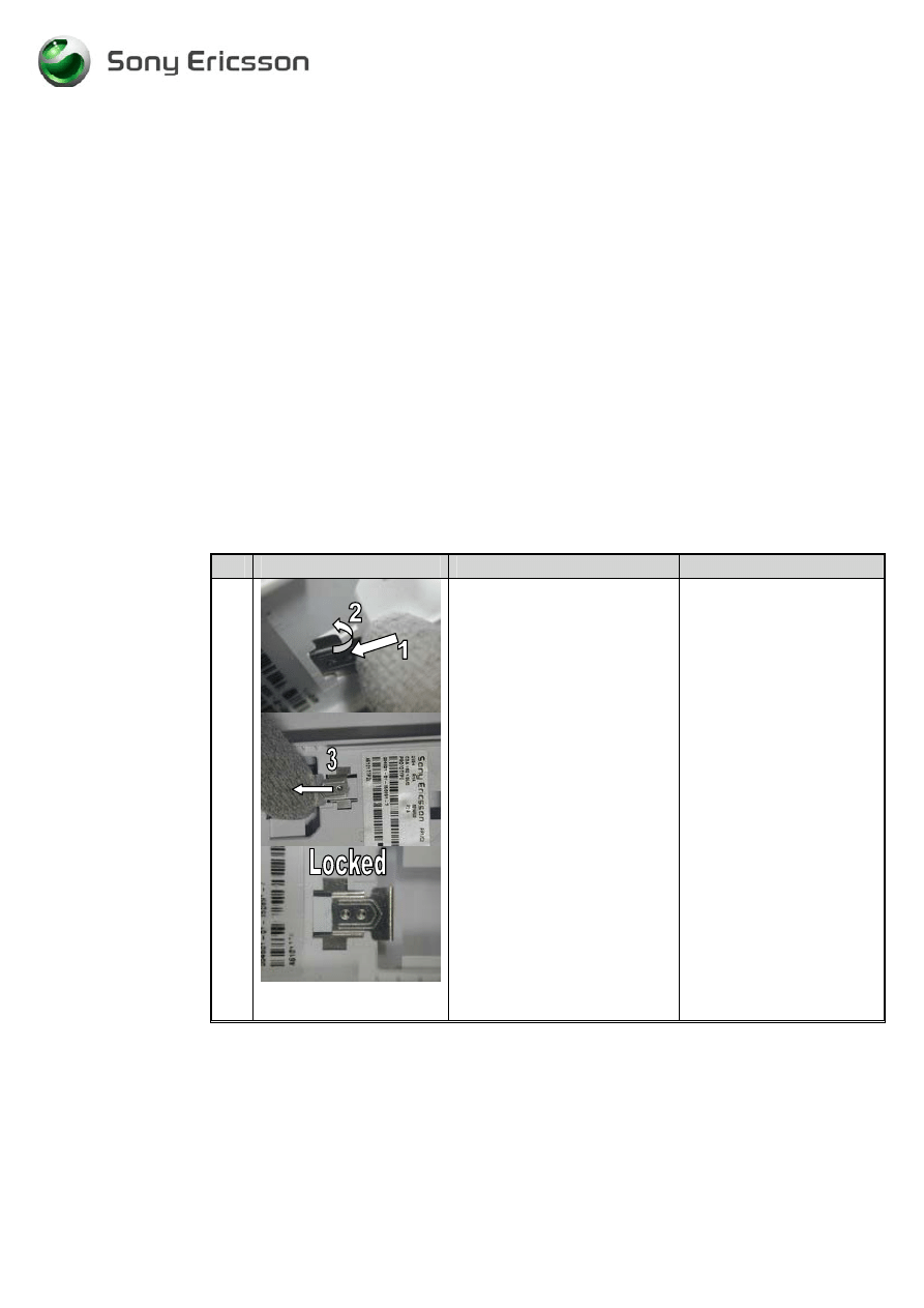
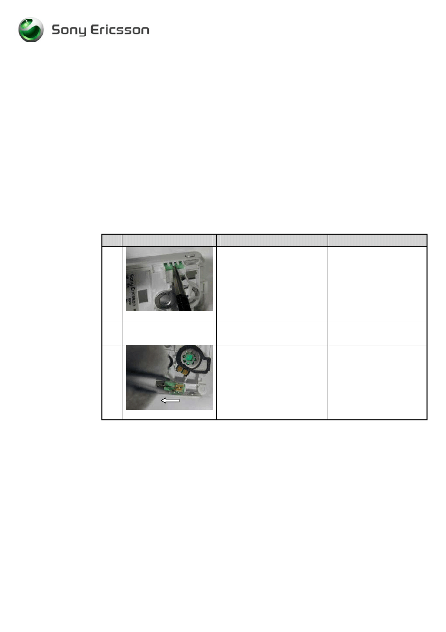
1
fig2.1
Put the SIM-lock lid into the
frame cavity (1) flip it down
(2) and lock it (3).
(fig 2.1)
-
9
-
Working Instructions, SP/Mechanical
3/000 21-1/FEA 209 544/76 E
SonyEricsson Mobile Communications AB
9(32)
# Figure
Instruction
Note
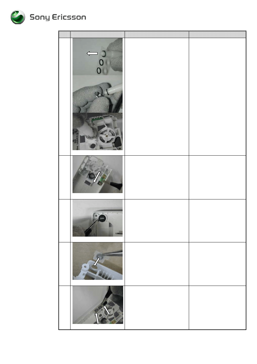
2
fig 2.2
Remove the camera gasket
from the carrier tape with the
camera gasket tool
Mount the camera gasket in
the camera ring with the
Camera gasket tool.
Mount the camera ring in the
frame cavity with the camera
gasket tool
.
(fig2.2)
Make sure that the
adhesive side is up (in the
arrow direction).
Make sure the camera ring
is oriented correctly.
The text “33mm” shall be
at the same side as the
antenna connector opening.
3
fig2.3
Mount the vibrator with a pair
of tweezers. Push it gently
down, with the contact springs
up, into the frame cavity with
the flywheel in the arrow
direction.
( fig 2.3).
Do not touch or damage
the vibrator contact
springs.
4
fig2.4
Put the microphone in its place
with a pair of tweezers. The
microphone does not have to
be mounted in any special
direction.
(fig2.4)
Do not touch the elastomer
with your fingers but make
sure the elastomer is
pointing upwards.
5
fig2.5
Mount the internet access key
with the narrow side down.
Use a pair of tweezers. The
rubber mat extended must be
tight attached to the cavity
walls.
( fig 2.5)
Be careful not to damage
the rubber with the pair of
tweezers (arrow).
6
fig2.6
Mount the volume/camera key
with a pair of tweezers.
The rubber mat extended must
be fitted behind the support
pegs at the arrows.
( fig 2.6)
Make sure that the
volume/camera key rubber
has contact with the Frame
cavity walls.
Be careful not to damage
the rubber with the pair of
tweezers.
-
10
-
Working Instructions, SP/Mechanical
3/000 21-1/FEA 209 544/76 E
SonyEricsson Mobile Communications AB
10(32)
# Figure
Instruction
Note
7
fig2.7
Pick up the speaker from the
tape & reel with the flex film
assembly tool and mount the
speaker in the Frame cavity.
( fig.2.7).
The contact pads on the
speaker mus be mounted
upwards.
Do not contaminate the
speaker contact pads.
8
fig2.8
Mount the speaker gasket over
the speaker. The gasket shall
not cover the contact pads and
speaker cavity edge at the
arrows.
( fig 2.8)
9
fig 2.9
Mount the system connector
on the PCB with your fingers.
Push it on in the arrow
direction
( fig 2.9)
The system connector will
be straight and parallel to
the bottom line of the PCB.
Wrongly mounted it can
cause damage to the small
components close to the
PCB bottom line.
10
fig 2.10
Mount the sound channel
gasket on the PCB with a pair
of tweezers.
Use the IRDA sidewall (1), the
PCB edge (2) and the PCB cut
(3) to place it in the correct
position.
(fig2.10)
11
fig 2.11
Mount the camera holder over
the shielding can with your
fingers. Snap fit the holder
centred over the shielding can
and make sure that the camera
stop pin (arrow) is correctly
oriented.
( fig 2.11)
The camera holder has
normally not been removed
in disassembly.
This is only to be done if
the camera holder has been
removed by accident.
-
11
-
Working Instructions, SP/Mechanical
3/000 21-1/FEA 209 544/76 E
SonyEricsson Mobile Communications AB
11(32)
# Figure
Instruction
Note
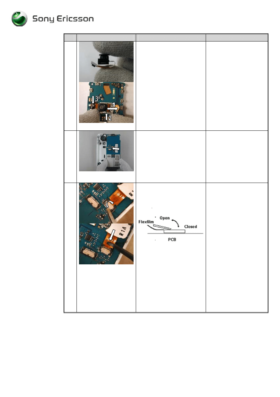
12
fig2.12
Pick up the camera with your
fingers. The flex film on the
camera must be folded under
the camera.
Push the camera into the
camera holder (1) and use the
camera stop pins (2) for the
right position.
Snap fit the camera flex film
(3) on to the PCB connector
with your fingers.
(fig2.12)
13
fig2.13
Place the PCB in the frame
cavity.
Start by putting the volume
and camera switch side into
frame cavity and then lay the
PCB down.
(fig2.13).
Make sure that the
switches on the PCB are in
contact with the
camera/volume key.
Check also that the switch
for internet is in contact
with the internet key.
14
fig 2.14
Open the dome foil assembly
ZIF connector.
Take a dome foil assembly
and mount it in the ZIF
connector. Push it into the ZIF
connector with the flex film
assembly tool. It is in the
correct position when the edge
is tight to the connector. Close
the connector with a pair of
tweezers.
(fig 2.14)
Be careful not to damage
the flex film with the flex
film assembly tool.
Make sure the ZIF
connector is properly
closed.
When the connector is
closed a gap between the
flex film edge and the
connector is visible.
-
12
-
Working Instructions, SP/Mechanical
3/000 21-1/FEA 209 544/76 E
SonyEricsson Mobile Communications AB
12(32)
# Figure
Instruction
Note
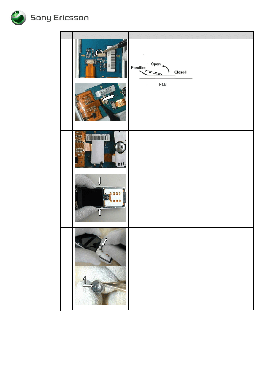
15
fig2.15
Open the display ZIF
connector.
Assemble the flex film into the
ZIF connector. Use the flex
film assembly tool. Close the
connector with a pair of
tweezers.
( fig 2.15)
Make sure the flex film is
in the proper position
before closing the ZIF
connector.
Be careful not to damage
the flex film with the tool.
Make sure that the ZIF
connector is properly
closed.
16
fig2.16
Assemble a new ZIF tape over
the two ZIF connectors by
hand or with a pair of
tweezers.
(fig 2.16)
Do not cover PWB-label
17
fig 2.16
Gently press the display edges
with your thumbs until the two
latches at the arrows locks the
display assembly in the proper
position with a “click” sound.
( fig 2.16)
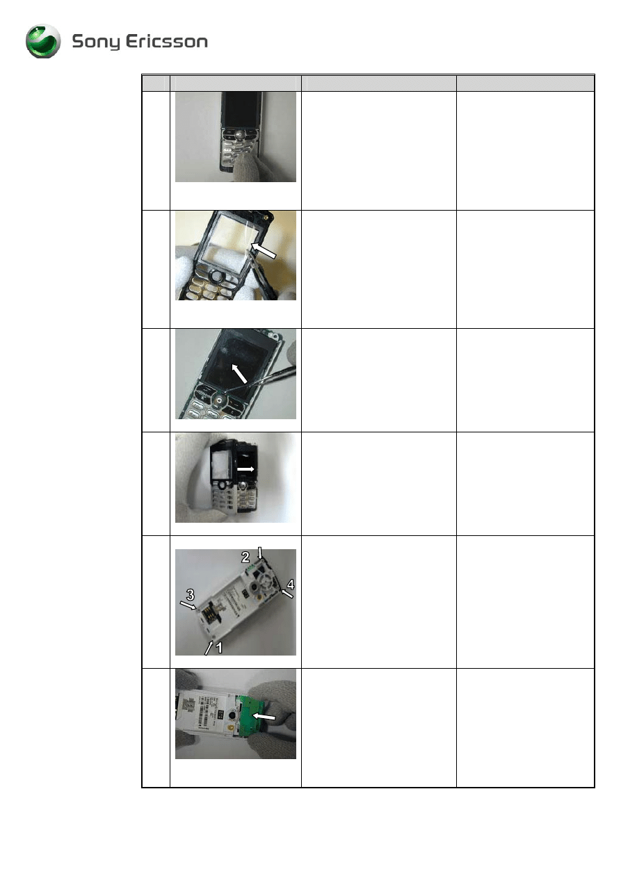
18
fig 2.17
Press the joystick button down
onto the square plastic pin on
the joystick switch.
Make assure the gasket (1) is
left on the button
(fig2.17)
The button does not have
to be oriented in any
special direction.
-
13
-
Working Instructions, SP/Mechanical
3/000 21-1/FEA 209 544/76 E
SonyEricsson Mobile Communications AB
13(32)
# Figure
Instruction
Note
19
fig2.18
Pick up the keyboard with
your fingers and mount it over
the dome foil assembly.
Use the 4 guiding pins on the
dome foil assembly to mount
the keyboard in its correct
position.
(fig2.18.)
20
fig2.19
Pick up the front. Make sure
that no dust, particles or
adhesive remains on the glass.
(fig2.19)
If you are going to use a
new front, don´t forget to
remove the dust protection
foil inside the front with a
pair of tweezers.
Be careful not to scratch
the inside of the window
with the pair of tweezers.
21
fig2.20
Extra paragraph.
(fig2.20)
If you have assembled a
new LCD display: Don`t
forget to remove the
display protection foil with
a pair of tweezers before
assembling the front (See
fig 2.20).
22
fig 2.21
Place the front over the frame.
( fig 2.21)
Very important: Check for
dust inside the phone
before assembling the
front.
Use air blow equipment
23
fig2.22
Mount the screws with
washers in the order 1 to 4.
(fig2.22)
Use Torque screwdriver
torx no 6 set to 20 Ncm
Screw until the torque is
reached.
Removed screws cannot be
reused and must be
scrapped.
24
fig2.23
Place the antenna assembly on
the cavity as the picture shows
with your fingers.
Then push the antenna
assembly in the arrow
direction until a click sound is
heard.
(fig 2.23)
Be careful not to damage
the pogo pins on the board.
-
14
-
Working Instructions, SP/Mechanical
3/000 21-1/FEA 209 544/76 E
SonyEricsson Mobile Communications AB
14(32)
# Figure
Instruction
Note
25
fig2.24
Mount the on/off key with
your fingers (1).
The narrow end on the on/off
key (2) shall be mounted in the
front.
Correct oriented
(fig2.24)
26
fig 2.25
Mount the rubber plug for the
external antenna connector.
(fig 2.25)
Make sure the rubber plug
is correct oriented.
See the cut corner at the
arrow.
27
fig2.26
Push the antenna cover in the
arrow direction over the
antenna assembly with your
fingers.
( fig 2.26)
Make sure that the antenna
cover has not been
damaged when opening the
phone. If the close clip or
any other part is damaged,
the antenna cover must be
replaced.
28
fig2.27
Push and press on the antenna
cover with your thumbs until it
properly fits in place with a
click sound.
( fig 2.27)
Press down against the
frame where the left snap
lock is located on the
antenna cover.
-
15
-
Working Instructions, SP/Mechanical
3/000 21-1/FEA 209 544/76 E
SonyEricsson Mobile Communications AB
15(32)
3 Replacement of Mechanical Parts
3.1 Microphone
3.1.1
Process tools
•
Pair of tweezers
3.1.2
Equipment
•
ESD-gloves (cotton gloves)
•
ESD-wristband
3.1.3
Instructions
•
Disassemble the phone as described in 1 Disassembly
# Figure
Instruction
Note
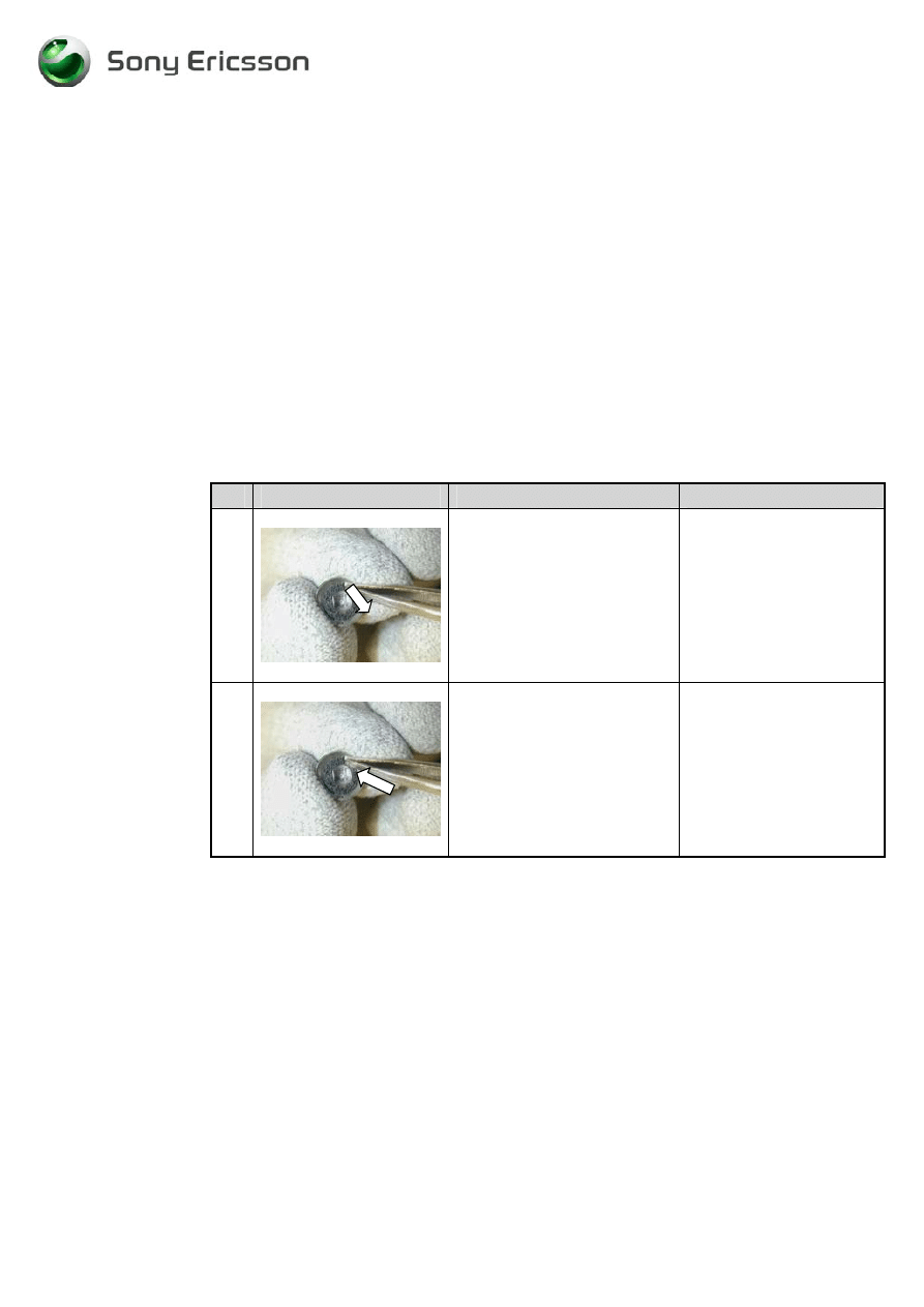
1
fig 3.1.1
Remove the microphone from
the frame cavity with a pair of
tweezers.
(fig3.1.1)
2
fig3.1.2
Pick up the new microphone
with a pair of tweezers.
Mount the microphone in the
cavity in the frame. Press the
microphone to the bottom of
the frame cavity
fig3.1.2)
Do not touch the
elastomer.
The microphone does not
have to be oriented in any
special direction except the
elastomer that must be
pointing upwards
•
Assemble the phone as described in 2 Reassembly
-
16
-
Working Instructions, SP/Mechanical
3/000 21-1/FEA 209 544/76 E
SonyEricsson Mobile Communications AB
16(32)
3.2 Vibrator
Assembly
3.2.1
Process Tools
•
Pair of tweezers.
3.2.2
Equipment
•
ESD-gloves (cotton gloves)
•
ESD-wristband
3.2.3
Instructions
•
Disassemble the phone as described in 1 Disassembly
# Figure
Instruction
Note
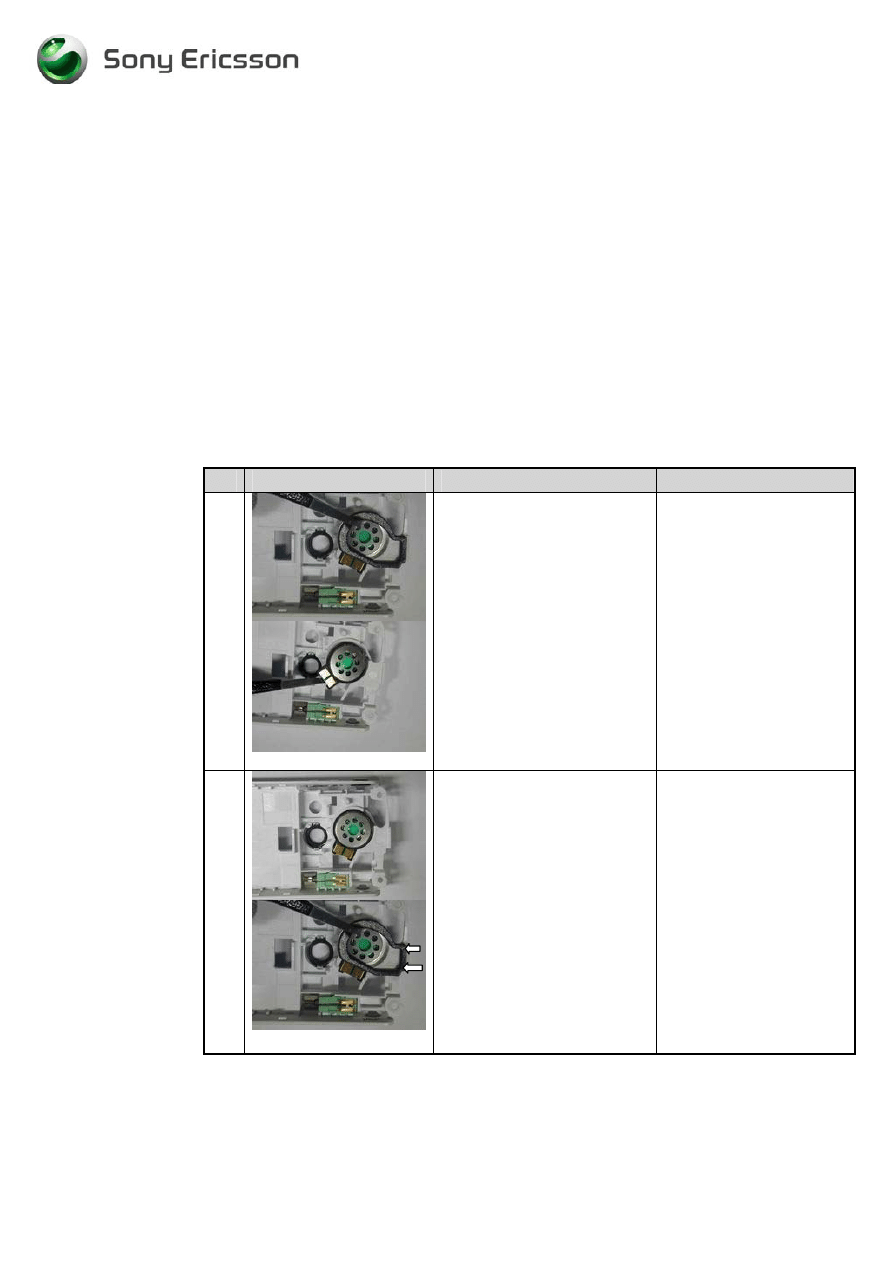
1
fig3.2.1
Remove the vibrator. Use a
pair of tweezers.
(fig 3.2.1)
To remove the vibrator
press on it from the rear
side of the frame
2
Take a new vibrator.
Hold the vibrator on the
rubber parts.
3
fig3.2.2
Mount the vibrator in the
frame cavity with a pair of
tweezers.
(fig3.2.2).
Do not touch or damage
the vibrator contact
springs.
The flywheel shall be in
the arrow direction
•
Assemble the phone as described in 2 Reassembly
-
17
-
Working Instructions, SP/Mechanical
3/000 21-1/FEA 209 544/76 E
SonyEricsson Mobile Communications AB
17(32)
3.3 SIM-lock
lid
3.3.1
Equipment
•
ESD-gloves (cotton gloves)
•
ESD-wristband
3.3.2
Instructions
•
Disassemble the phone as described in 1 Disassembly
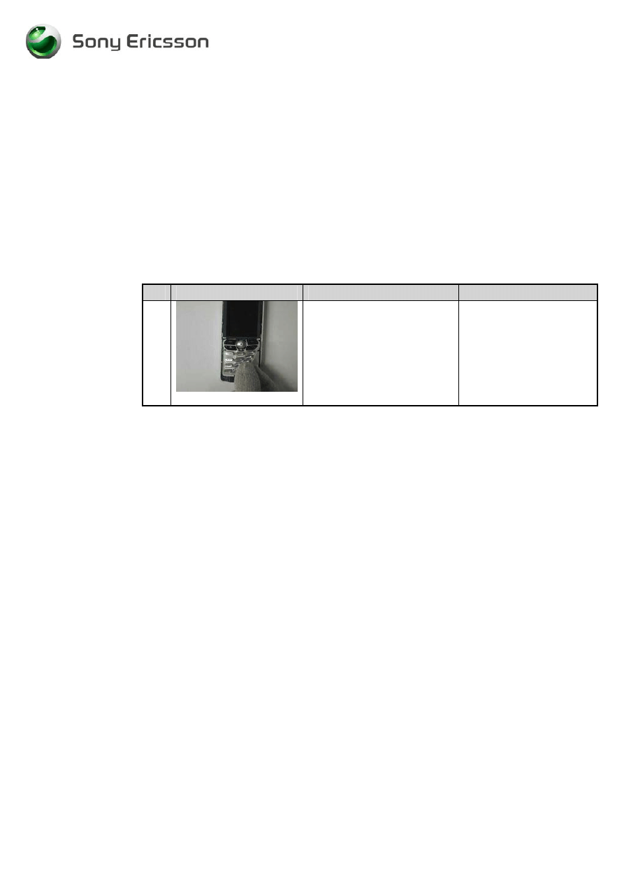
1
fig3.3. 1
Remove the old SIM-lock lid
with your fingers by first
pushing it in open position (1)
Lift it up (2) and pull it
backwards (3)
(fig3.3.1)
2
fig3.3.2
Mount the SIM-lock lid with
your fingers.
Put the SIM-lock lid into the
frame (1) cavity and push it
down (2)
Lock the SIM-lock lid by
pushing it backwards (3).
(fig3.3.2)
•
Assemble the phone as described in 2 Reassembly
-
18
-
Working Instructions, SP/Mechanical
3/000 21-1/FEA 209 544/76 E
SonyEricsson Mobile Communications AB
18(32)
3.4
Speaker
3.4.1
Process
Tools
•
Pair of tweezers
3.4.2
Equipment
•
ESD-gloves (cotton gloves)
•
ESD-wristband
3.4.3
Instructions
•
Disassemble the phone as described in 1 Disassembly
# Figure
Instruction
Note
1
fig3.4.1
Remove the speaker gasket
with a pair of tweezers.
Remove the speaker with a
pair of tweezers.
(fig3.4.1).
2
fig3.4.2
Mount the speaker in the
frame cavity with a pair of
tweezers
Mount the speaker gasket over
the speaker. The gasket shall
not cover the contact pads and
speaker cavity edge at the
arrows.
( fig3.4.2)
Do not touch the speaker
pads with your fingers.
•
Assemble the phone as described in 2 Reassembly
-
19
-
Working Instructions, SP/Mechanical
3/000 21-1/FEA 209 544/76 E
SonyEricsson Mobile Communications AB
19(32)
3.5 Keyboard
3.5.1
Equipment
•
ESD-gloves (cotton gloves)
•
ESD-wristband
3.5.2
Instructions
•
Disassemble the phone as described in 1 Disassembly
# Figure
Instruction
Note
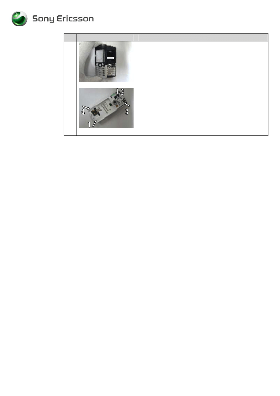
1
fig3.5.1
Replace the old keys with a
new set with your fingers.
(fig3.5.1)
Use the 4 guiding pins on
the dome foil assembly to
mount the keypad in the
proper position.
•
Assemble the phone as described in 2 Reassembly
-
20
-
Working Instructions, SP/Mechanical
3/000 21-1/FEA 209 544/76 E
SonyEricsson Mobile Communications AB
20(32)
3.6 Volume/Camera
Key
3.6.1
Process Tools
•
Pair of tweezers.
3.6.2
Equipment
•
ESD-gloves (cotton gloves)
•
ESD-wristband
3.6.3
Instructions
•
Disassemble the phone as described in 1 Disassembly
# Figure
Instruction
Note
1
fig3.6.1
Gently push the
Volume/camera key in from
the outside (1) then pick it up
on the inside with a pair of
tweezers.
(fig3.6.1)
Be gentle !
The rubber can be
damaged when picking it
up (2)
2
fig3.6.2
Take a new volume/camera
key and mount it in the frame
with a pair of tweezers.
The rubber mat extend must be
fitted behind the support pegs
at the arrows.
( fig 3.6.2)
Make sure that the
volume/camera key rubber
has contact with the Frame
cavity walls.
Be gentle !
The rubber can be
damaged when picking it
up
•
Assemble the phone as described in 2 Reassembly
-
21
-
Working Instructions, SP/Mechanical
3/000 21-1/FEA 209 544/76 E
SonyEricsson Mobile Communications AB
21(32)
3.7 Internet
Access
Key
3.7.1
Process tools
•
Pair of tweezers
3.7.2
Equipment
•
ESD-gloves (cotton gloves)
•
ESD-wristband
3.7.3
Instructions
•
Disassemble the phone as described in 1 Disassembly
# Figure
Instruction
Note
1
fig3.7.1
Remove the old internet access
key by gently pushing it from
the outside in (1) and then pick
it up on the inside with a pair
of tweezers (2).
(fig 3.7.1)
Be gentle !
The rubber can be
damaged when picking it
up (2)
2
fig3.7.2
Assemble a new the internet
access key with a pair of
tweezers. The rubber mat
extend must be tight attached
to the cavity walls.
(fig 3.7.2)
Be careful not to damage
the rubber with the pair of
tweezers (arrow).
•
Assemble the phone as described in 2 Reassembly
-
22
-
Working Instructions, SP/Mechanical
3/000 21-1/FEA 209 544/76 E
SonyEricsson Mobile Communications AB
22(32)
3.8 Sound
channel
Gasket
3.8.1
Process Tool
•
Pair of tweezers.
3.8.2
Equipment
•
ESD-gloves (cotton gloves)
•
ESD-wristband
3.8.3
Instructions
•
Disassemble the phone as described in 1 Disassembly
# Figure
Instruction
Note
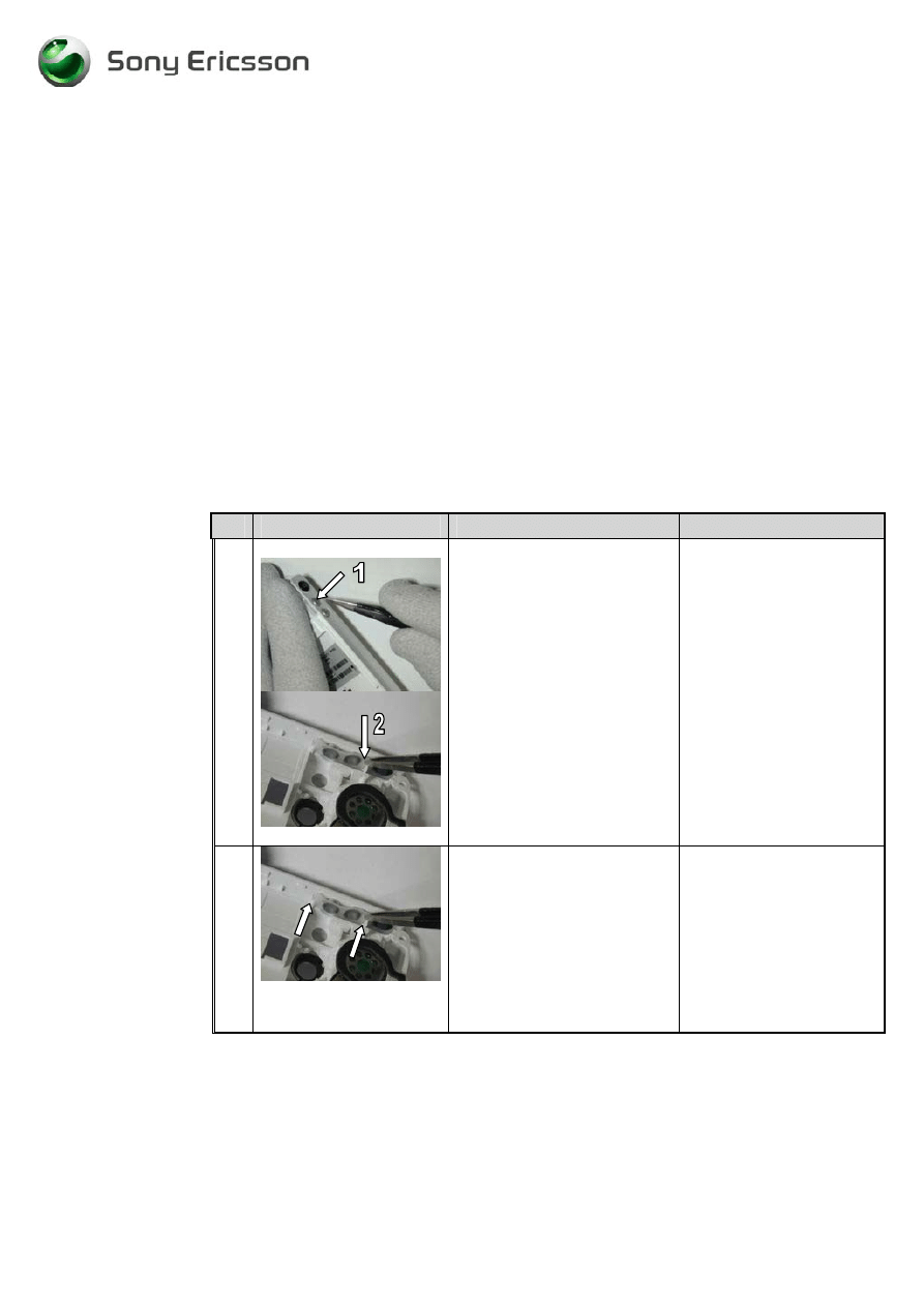
1
fig3.8.1
Remove the sound channel
gasket from the PCB with a
pair of tweezers.
(fig3.8.1)
Do not reuse the sound
channel gasket.
2
Take a new sound channel
gasket with a pair of tweezers.
3
fig3.8.2
Mount the sound channel
gasket onto the PCB. Use the
IRDA sidewall (1), the PCB
edge (2) and the PCB cut (3)
to place it in the proper
position.
( fig 3.8.2)
•
Assemble the phone as described in 2 Reassembly
-
23
-
Working Instructions, SP/Mechanical
3/000 21-1/FEA 209 544/76 E
SonyEricsson Mobile Communications AB
23(32)
3.9 Joystick
gasket
3.9.1
Process Tool
•
Pair of tweezers.
3.9.2
Equipment
•
ESD-gloves (cotton gloves)
•
ESD-wristband
3.9.3
Instructions
●
Disassemble the phone as described in 1 Disassembly
# Figure
Instruction
Note
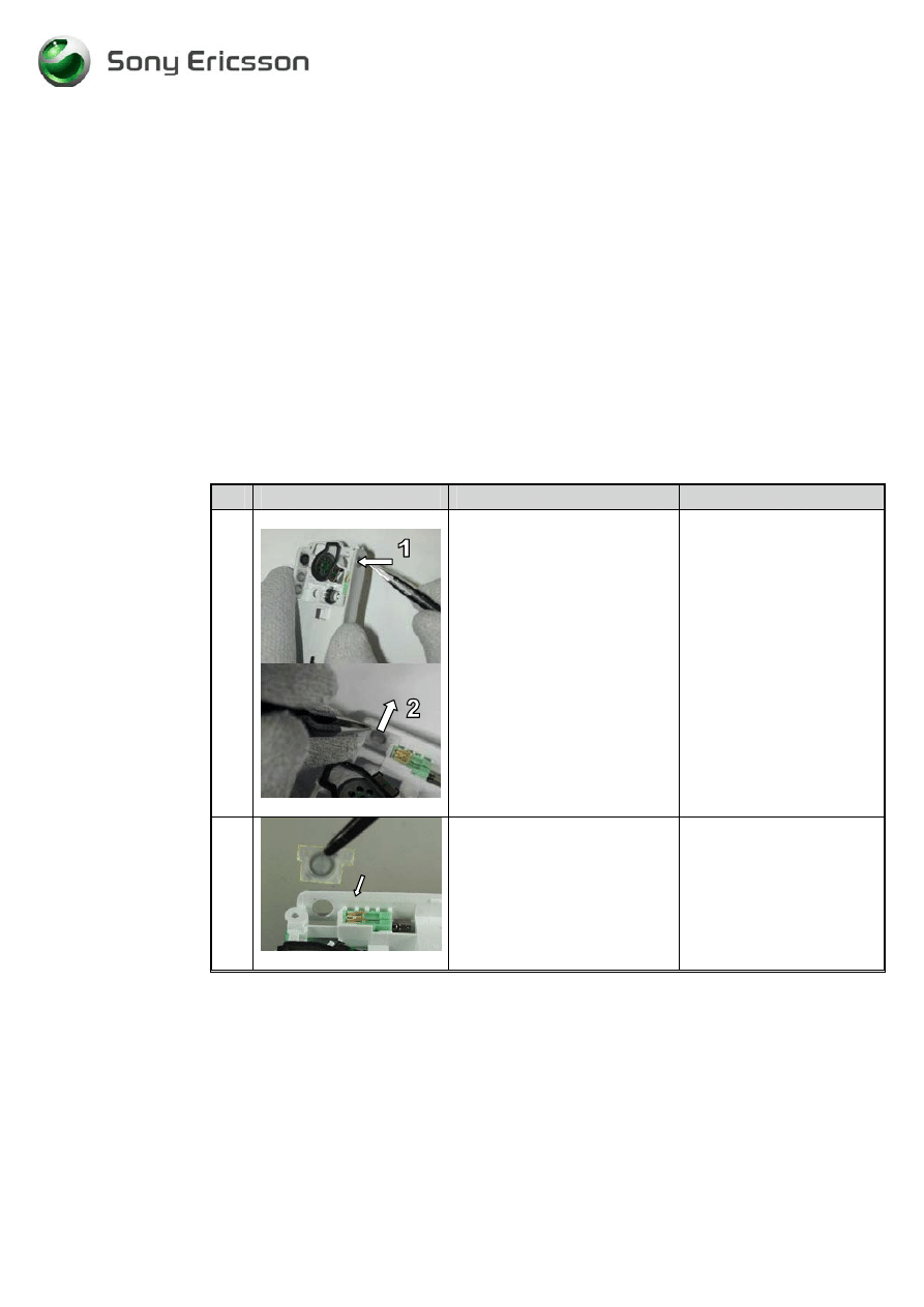
1
fig 3.9.1
Remove the old joystick
gasket with a pair of tweezers.
The joystick gasket is not
always possible to remove in
one piece.
(fig 3.9.1)
Remove all left residues
with alcohol.
2
fig 3.9.2
Pick up the joystick gasket
with a pair of tweezers and the
joystick with your fingers.
Place the gasket in the centre
of the joystick button
. ( fig 3.9.2)
•
Assemble the phone as described in 2 Reassembly
-
24
-
Working Instructions, SP/Mechanical
3/000 21-1/FEA 209 544/76 E
SonyEricsson Mobile Communications AB
24(32)
3.10
Antenna assembly
3.10.1
Equipment
•
ESD-gloves (cotton gloves)
•
ESD-wristband
3.10.2
Instructions
•
Disasseble the phone as described in 1 Disassembly
# Figure
Instruction
Note
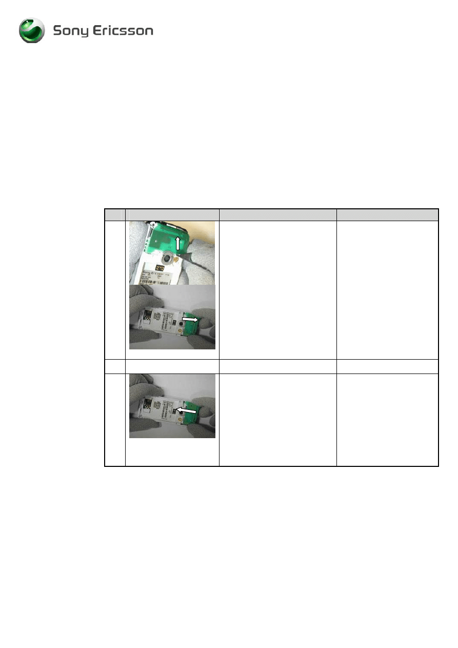
1
fig3.10..1
Remove the antenna assembly
Use the front opening tool to
release it and then gently
remove it with your fingers
(fig 3.10.1)
Push the antenna assembly
forward in the arrow
direction.
2
Take a new antenna assembly.
3
fig3.10.2
Place the antenna assembly on
the cavity with your fingers as
the picture shows.
Then push the antenna
assembly in the arrow direction
until a click sound is heard.
(fig 3.10.2)
Be careful not to damage
the pogo pins on the board.
•
Assemble the phone as described in 2 Reassembly
-
25
-
Working Instructions, SP/Mechanical
3/000 21-1/FEA 209 544/76 E
SonyEricsson Mobile Communications AB
25(32)
3.11 Dome
Foil
assembly
3.11.1 Process
tool
•
Blunt Pair of tweezers
•
Flexfilm assembly tool NTZ 112 521
3.11.2
Equipment
•
ESD-gloves (cotton gloves)
•
ESD-wristband
3.11.3
Instructions
•
Disassemble the phone as described in 1 Disassembly
#
Figure
Instruction
Note
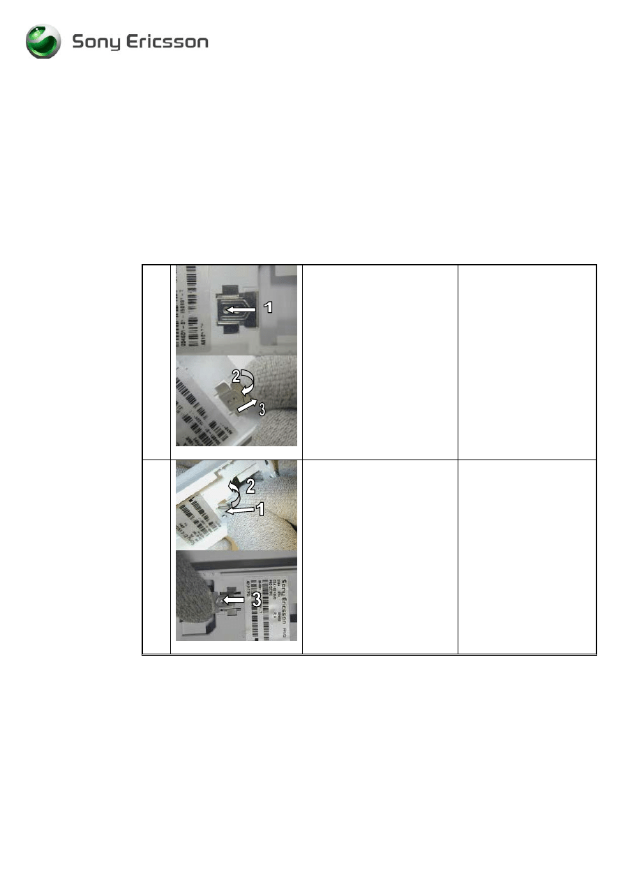
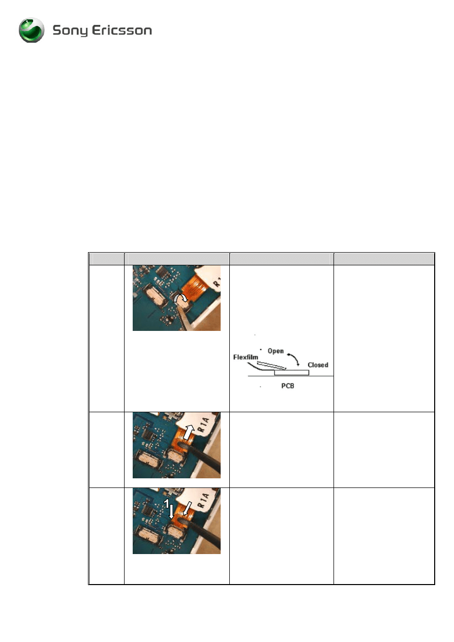
1
Fig3.11.1
If present, remove the
protective tape placed over
the two connectors. Open
the ZIF connector to the
dome foil assembly with a
pair of tweezers.
(fig3.11.1)
Be careful not to damage
the ZIF-connector.
2
Fig 3.11.2
Remove the dome foil
assembly with the flex film
assembly tool.
(fig 3.11.2)
3
Fig 3.11.3
Take a new dome foil
assembly and mount it in
the ZIF connector. Push it
into the connector with the
flex film assembly tool. It is
in the correct position when
the edge (1) is tight to the
connector.
(fig 3.11.3)
Be careful not to damage
the flex film with the flex
film assembly tool.
-
26
-
Working Instructions, SP/Mechanical
3/000 21-1/FEA 209 544/76 E
SonyEricsson Mobile Communications AB
26(32)
#
Figure
Instruction
Note
4
Fig3.11.4
Close the ZIF connector
with a pair of tweezers.
(fig3.11.4)
Then place protective tape
to cover both connectors.
Do not cover PWB-label.
When the connector is
closed a gap between the
flex film edge and the
connector is visible.
•
Assemble the phone as described in 2 Reassembly
-
27
-
Working Instructions, SP/Mechanical
3/000 21-1/FEA 209 544/76 E
SonyEricsson Mobile Communications AB
27(32)
3.12 Display
assembly
3.12.1 Process
tool
•
Blunt Pair of tweezers
•
Flex film assembly tool NTZ 112 521
3.12.2
Equipment
•
ESD-gloves (cotton gloves)
•
ESD-wristband
3.12.3
Instructions
•
Disassembly the phone as described in 1 Disassembly
# Figure
Instruction
Note
1
fig3.12.1
Lift up the display with your
fingers, if present, remove
the protective tape placed
over the two connectors and
open the ZIF- connector
connected to the display
with a pair of tweezers.
Remove the Flex film from
the ZIF-connector with the
flex film assembly tool.
( fig 3.12.1)
Be careful not to damage
the ZIF-connector.
Do not touch the display-
glass with your fingers.
Use the correct pair of
tweezers !!
Be careful not to damage
the flex film with the flex
film assembly tool.
2
fig3.12.2
Take a new display
assembly and mount it in
the ZIF connector. Push the
flex film into the connector
with the flex film assembly
tool. It is in the correct
position when the edge (1)
is tight to the connector.
(fig3.12.2).
Be careful not to damage
the flex film with the flex
film assembly tool.
-
28
-
Working Instructions, SP/Mechanical
3/000 21-1/FEA 209 544/76 E
SonyEricsson Mobile Communications AB
28(32)
# Figure
Instruction
Note
3
fig 3.12.3
Close the FPC connector
with a pair of tweezers.
(fig3.12.3)
Be careful not to damage
the flex film with the tool.
Make sure that the FPC
connector is properly
closed.
4
fig 3.12.4
Assemble a new ZIF tape
over the two ZIF connectors
by hand or with a pair of
tweezers.
(fig3.12.4).
Do not cover PWB-label
5
fig 3.12.5
If you are assembling a
new LCD. Don`t forget to
remove the LCD display
protection foil with a pair
of tweezers before
reassembling the front.
•
Assemble the phone as described in 2 Reassembly
-
29
-
Working Instructions, SP/Mechanical
3/000 21-1/FEA 209 544/76 E
SonyEricsson Mobile Communications AB
29(32)
3.13
Camera ring and camera ring gasket
3.13.1 Process
tool
•
Camera gasket tool NTZ 112 507
•
Pair of tweezers.
3.13.2
Equipment
•
ESD-gloves (cotton gloves)
•
ESD-wristband
3.13.3
Instructions
•
Disassemble the phone as described in 1 Disassembly
# Figure
Instruction
Note
1
fig3.13.1
Remove the camera ring by
pressing it out with the
camera gasket assembly
tool.
(Fig 3.13.1)
The camera ring is not to
be reused.
2
fig3.13.2
Remove the camera gasket
from the carrier tape with
the camera gasket tool
Mount the camera gasket in
the camera ring with the
Camera gasket tool.
Mount the camera ring in
the frame cavity with the
camera gasket tool
.
(fig3.13.2)
Make sure that the
adhesive side is up (in the
arrow direction).
Make sure the camera ring
is oriented correctly.
The text “33mm” must be
at the same side as the
antenna connector opening.
•
Assemble the phone as described in 2 Reassembly
-
30
-
Working Instructions, SP/Mechanical
3/000 21-1/FEA 209 544/76 E
SonyEricsson Mobile Communications AB
30(32)
3.14 Front replacement, Light Gasket
3.14.1 Process tools
•
Pair of tweezers.
3.14.2 Equipment
•
ESD-gloves (cotton gloves)
•
ESD-wristband
3.14.3 Instructions
●
Disassemble the phone as described in 1 Disassembly
# Figure
Instruction
Note
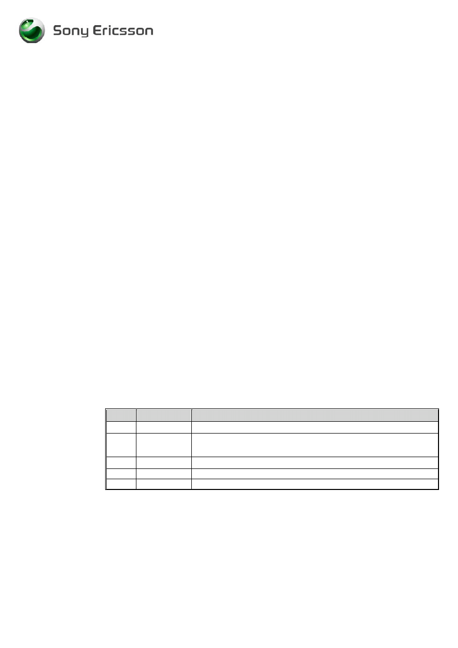
1
fig3.14.1
Remove the four screws at the
arrows.
(fig3.14.1)
Use screwdriver, torx no 6.
Removed screws cannot be
reused and must be
scrapped.
2
fig3.14.2
Mount the light gasket in the
front, use a pair of tweezers.
(fig 3.14.1)
New fronts are delivered
without light gasket
3
fig3.14.3
Pick up the front and remove
the dust protection foil inside
the front with a pair of
tweezers. Make sure no dust,
particles or adhesive remains
on the glass.
(fig3.14.3)
Be careful not to scratch
the inside of the window
with the pair of tweezers.
4
fig3.14.4
Remove the display protection
foil (if a new display is
assembled).
(fig3.14.4)
Be careful not to scratch
the surface of the LCD
display with the pair of
tweezers
-
31
-
Working Instructions, SP/Mechanical
3/000 21-1/FEA 209 544/76 E
SonyEricsson Mobile Communications AB
31(32)
# Figure
Instruction
Note
5
fig 3.14.5
Place the front over the frame.
(Fig 3.14.5)
Very important: Check for
dust inside the phone- both
inside the front and on the
LCD display before
assembling the front.
Use air blow equipment
6
fig3.14.6
Assemble the screws with
washer in the order 1 to 4.
(fig3.14.6)
Use Torque screwdriver
torx no 6 set to 20 Ncm
Screw until the torque is
reached.
Removed screws cannot be
reused and must be
scrapped.
●
Assemble the phone as described in 2 Reassembly
-
32
-
Working Instructions, SP/Mechanical
3/000 21-1/FEA 209 544/76 E
SonyEricsson Mobile Communications AB
32(32)
4. Process Tools for Label
•
Hot air blower.
•
Pair of tweezers.
4.1 Instructions
This instruction should be used when you intend to exchange an old label and/or mount a new
one.
1. Heat up the label with a hot air blower.
2. Carefully remove the label, make sure that all the residue is removed. Do not scratch the
frame.
3. Printing: The text must be fully readable visually and through bar code readers.
4. Take the new label and place it in the battery cavity. The label should be centred and
parallel to the sides of the cavity.
NOTE! Make sure there are no air bubbles under the label. Only one label is allowed in
the battery cavity.
5 Revision History
Rev. Date
Changes / Comments
E 2003-11-26
Added pictures of protective tape.
D
2003-11-20
Added instructions for protective tape over display and keyboard
connectors.
C
2003-06-06
Chaged picture of Zif -contact
B
2003-05-27
Additional note text when handling the antenna cover
A 2003-04-24
First
release
Wyszukiwarka
Podobne podstrony:
Sony Ericsson T303 instrukcja rozbiórki
Sony Ericsson T100 T105 instrukcja rozbiórki
Instrukcja obsługi telefonu Sony Ericsson K610i
Instrukcja Sony Ericsson W595
sony ericsson k770 installation instruction, mechanical
sony ericsson k770 test instruction, mechanical
Sony Ericsson GC79, TELEFONIA, Opisy telefonów
sony-ericsson, Analiza finasowa
sony-ericsson, PODSTAWY ZARZĄDZANIA
problemy Sony Ericsson
simlock, Telefony, SONY ERICSSON, C510
Sony Ericsson GC79, TELEFONIA, Opisy telefonów
sony ericsson k770 equipment list, mechanical
Sony Ericsson W910i EN
Sony Ericsson wprowadza dwa nowe modele W508 i C510
sony ericsson k770 part list, mechanical
Jak odzyskać usunięte smsy z telefonu sony ericsson xperia
Jak odzyskać smsy z telefonu sony ericsson
więcej podobnych podstron