
Working Instruction, Mechanical
1212-9365 Rev 1
1(42)
Working Instruction, Mechanical
Applicable for T303
CONTENTS
Introduction .............................................................................. 3
Equipment................................................................................. 4
General cautions ...................................................................... 5
Adhesives ................................................................................. 5
Disassembly ............................................................................. 6
Overview ................................................................................... 6
Battery Cover & Battery......................................................... 7
Antenna Cover ...................................................................... 8
PCB....................................................................................... 9
Rear Cover Assy ................................................................. 10
Slide Hinge Assy ................................................................. 11
Function Key FPC Assy ...................................................... 13
Display 128x160 TFT .......................................................... 14
Front Cover Assy................................................................. 15
Replacements......................................................................... 16
Battery Cover..........................................................................17
Bottom Cover U-Shape ..........................................................17
Keyboard .................................................................................17
Rear Cover Assy.....................................................................17
Function Key FPC Assy.........................................................17
Top Rear Cover.......................................................................17
Display 128x160 TFT ..............................................................17
Slide Hinge Assy ....................................................................18
Hinge FPC Assy......................................................................18
Camera 1.3 MPixel CMOS ......................................................18
Damper Camera......................................................................18
Magnet .....................................................................................18
Battery Connector 5pin & Liquid Intrusion Indicator .........19
Microphone Sponge Dust Net ...............................................21
Anti-Friction Block .................................................................21
Main Keypad FPC Assy .........................................................22
Function Key FPC Assy & Loudspeaker Box 38.5x19........23
Camera Window .....................................................................24
Plating Camera Sheet ............................................................25
Company Internal
©
Sony Ericsson Mobile Communications AB

Working Instruction, Mechanical
1212-9365 Rev 1
2(42)
Ear Speaker 11.0x7.0 Rectangular........................................26
Function Keyboard.................................................................27
Magnet .....................................................................................28
Conductive Rubber & Damper Stopper................................28
Damper Stopper .....................................................................29
KRH Label ...............................................................................29
Reassembly ............................................................................ 30
Overview .................................................................................30
Front Cover Assy................................................................. 31
Display 128x160 TFT .......................................................... 32
Function Key FPC Assy ...................................................... 33
Slide Hinge Assy ................................................................. 35
Rear Cover Assy ................................................................. 37
PCB..................................................................................... 38
Antenna Cover .................................................................... 39
Battery Cover & Battery....................................................... 41
Revision history ..................................................................... 42
©
Sony Ericsson Mobile Communications AB
Working Instruction, Mechanical
1212-9365 Rev 1
3(42)
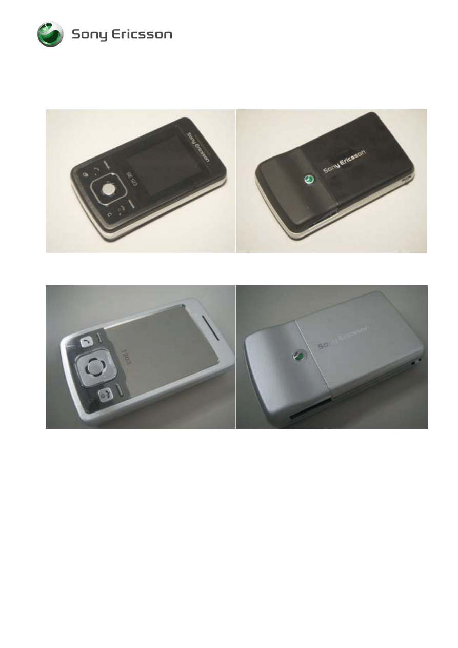
1 Introduction
T303 - Black
T303 - Silver
Company Internal
©
Sony Ericsson Mobile Communications AB
Working Instruction, Mechanical
1212-9365 Rev 1
4(42)
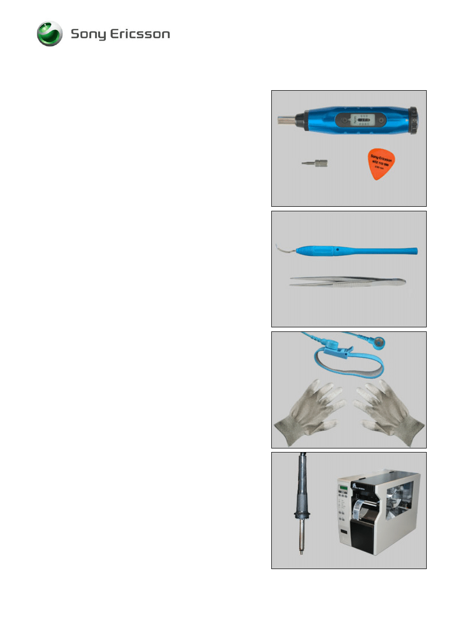
1.1 Equipment
SPECIAL TOOLS
Special tools can be found in the tool catalogue
• Screwdriver
• JCIS
Bits
• Guitar
Pick
STANDARD TOOLS
Standard tools text:
• Dentist Hook (optional)
• Pair of tweezers
ESD EQUIPMENT
Protect the phone from ESD damages whenever it has
been opened by using:
• ESD-wristband
• ESD-gloves
LABEL EQUIPMENT
The following special equipment is required when replacing
or installing a new label:
• Hot air flow solder station
• Zebra printer connected to computer
Company Internal
©
Sony Ericsson Mobile Communications AB

Working Instruction, Mechanical
1212-9365 Rev 1
5(42)
1.2 General cautions
The following cautions are considered to be generic for all phone models and will not be repeated in
the Disassembly, Replacements and Reassembly sections:
• S
WITCH OFF THE PHONE AND REMOVE ANY MEMORY STICK BEFORE THE START OF THE DISASSEMBLY
!
• K
EEP ALL CONTACT SURFACES CLEAN
!
• B
E CAREFUL WHEN USING TOOLS LIKE THE DENTIST HOOK
,
TWEEZERS
,
OPENING TOOLS
,
GUITAR PICK
ETC
.
TO AVOID SCRATCHES OR DAMAGES TO THE EXTERIOR AND INTERIOR PARTS OF THE PHONE
!
• B
E CAREFUL NOT TO DAMAGE ANY CONTACT SPRINGS
!
• R
EMEMBER TO REMOVE THE PROTECTION FOILS ON NEW PARTS SUCH AS THE FRONT COVER
AND
LCD!
• N
EVER TOUCH THE DISPLAY GLASS
!
• U
SE AIR BLOW EQUIPMENT TO KEEP THE FRONT WINDOW AND DISPLAY MODULE DUST FREE
!
1.3 Adhesives
Use a dentist hook and/or the tweezers to remove old adhesives.
Clean the surface with isopropyl alcohol before attaching new adhesives.
Company Internal
©
Sony Ericsson Mobile Communications AB
Working Instruction, Mechanical
1212-9365 Rev 1
6(42)
2 Disassembly
When you are going to replace a part being listed in Replacements, the instruction of that section
usually begins by directing you to this Disassembly section with a specification of the instructions you
have to carry out in order to disassemble the phone as far as needed before returning to
Replacements for the actual replacement.
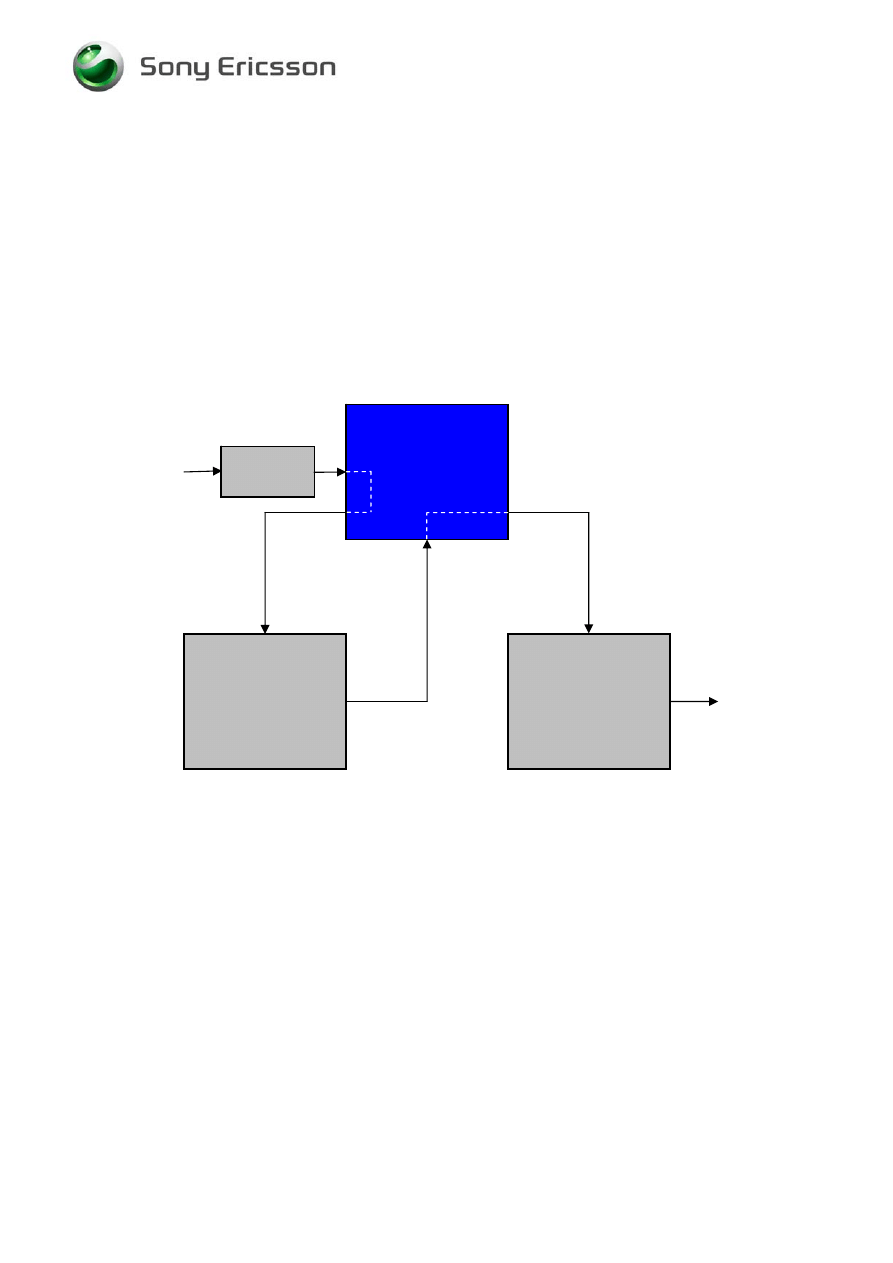
Start
DISASSEMBLY
REASSEMBLY
Content
page
REPLACEMENTS
Done
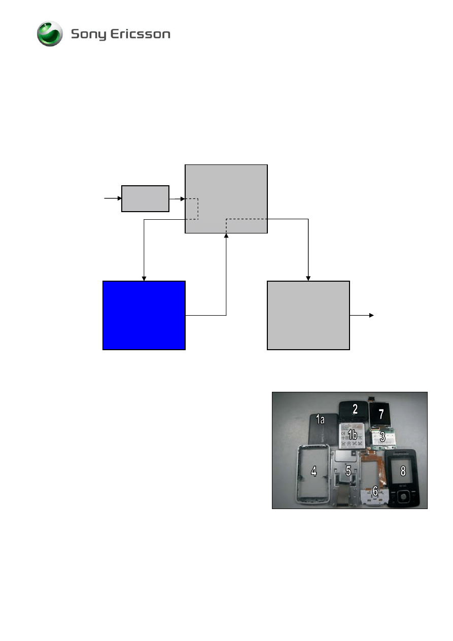
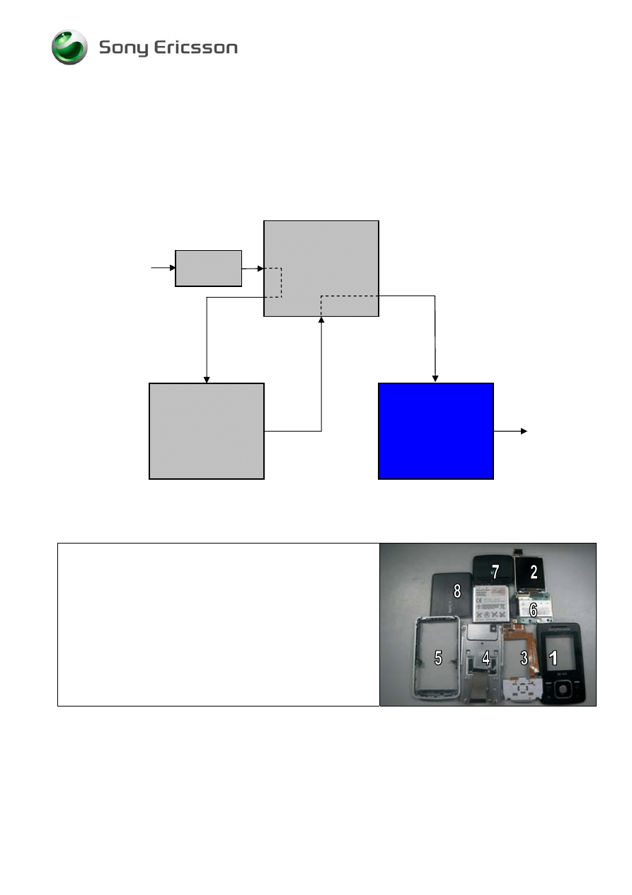
2.1 Overview
The disassembly is done in the following sequence:
1. Battery Cover (a) & Battery (b)
2. Antenna Cover
3. PCB
4. Rear Cover Assy
5. Slide Hinge Assy
6. Function Key FPC Assy
7. Display 128x160 TFT
8. Front Cover Assy
Company Internal
©
Sony Ericsson Mobile Communications AB
Working Instruction, Mechanical
1212-9365 Rev 1
7(42)
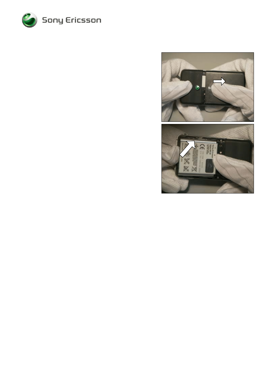
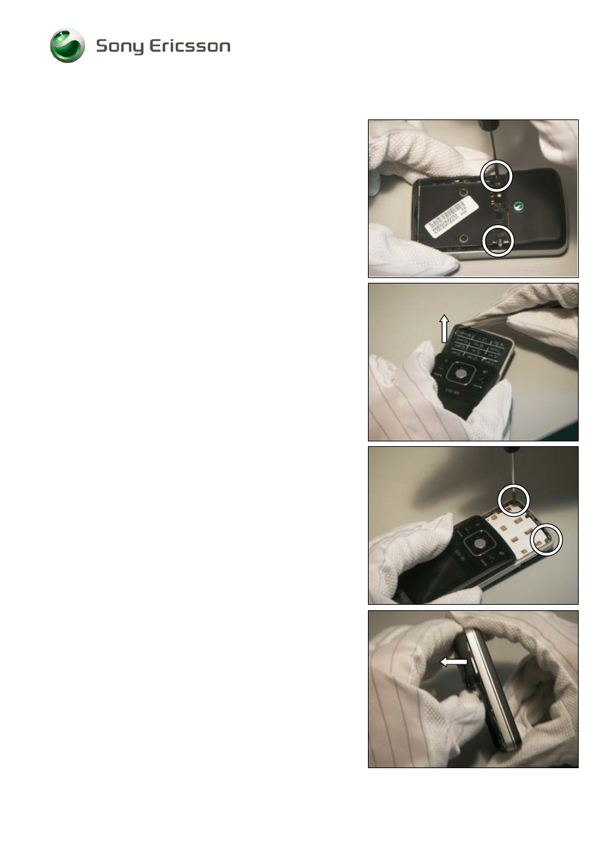
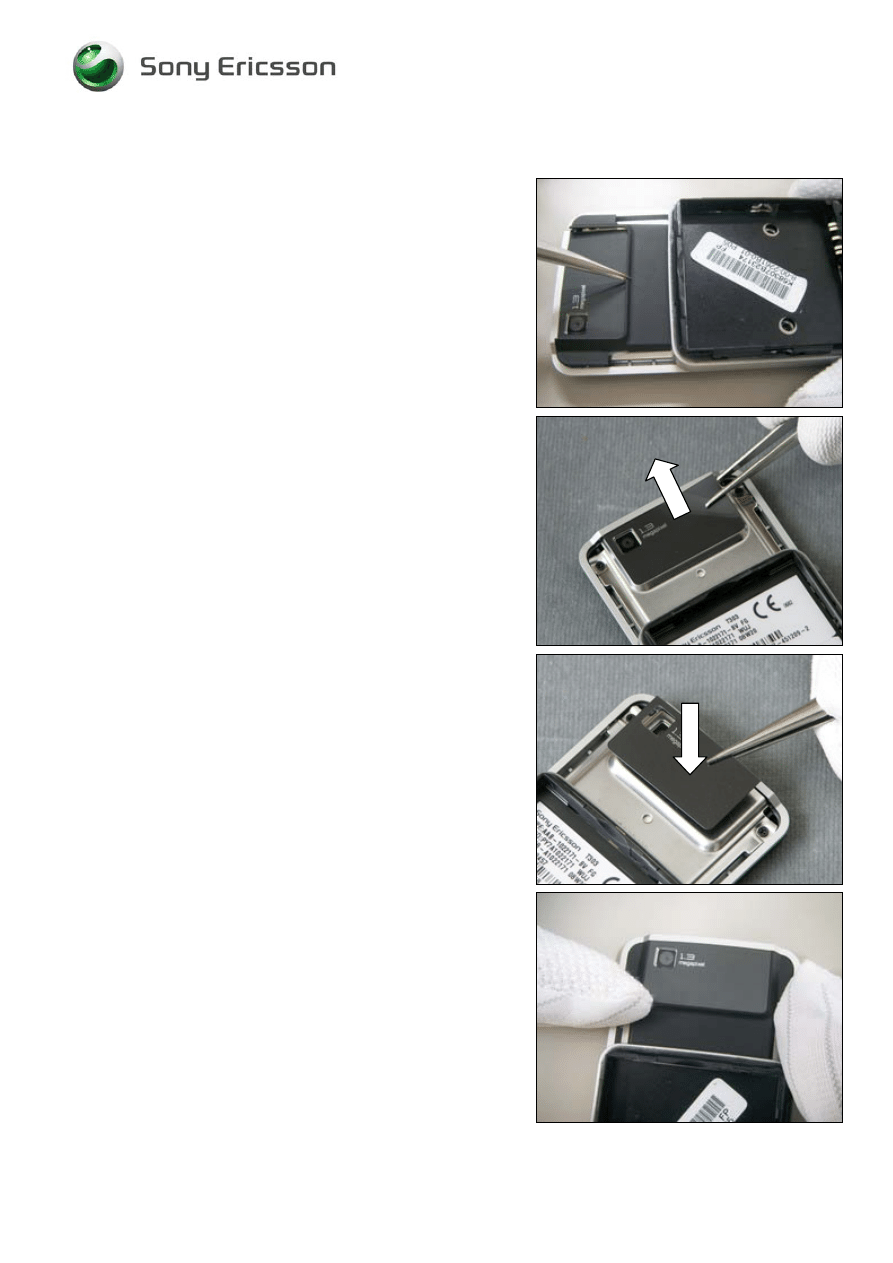
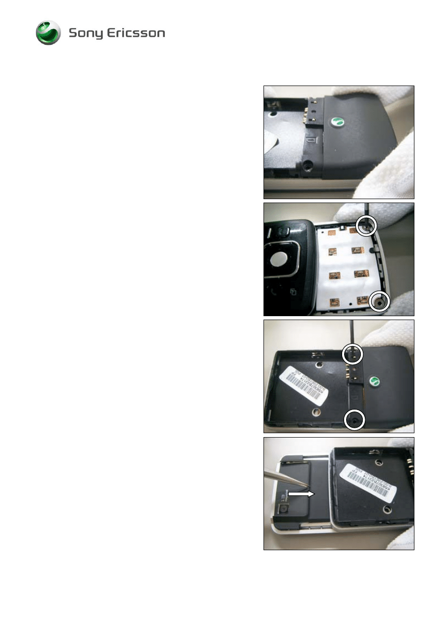
2.1.1 Battery Cover & Battery
Hold the phone and slide off the battery cover.
Use your thumb to push up the Battery.
Company Internal
©
Sony Ericsson Mobile Communications AB
Working Instruction, Mechanical
1212-9365 Rev 1
8(42)
2.1.2 Antenna
Cover
Release the two screws with a screwdriver
Use a pair of tweezers to remove the Bottom Cover
U-Shape and pick up Main keypad.
Release the two screws with a screwdriver.
Use your thumb to remove the antenna cover from Rear
Cover.
Company Internal
©
Sony Ericsson Mobile Communications AB
Working Instruction, Mechanical
1212-9365 Rev 1
9(42)
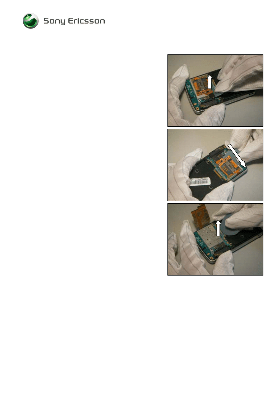
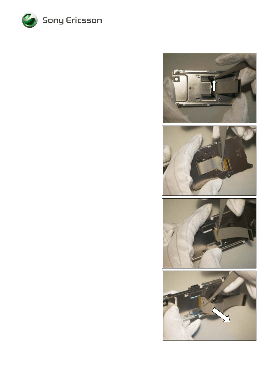
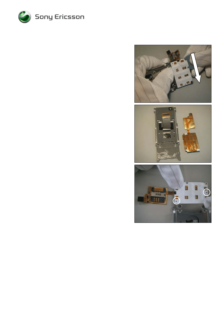
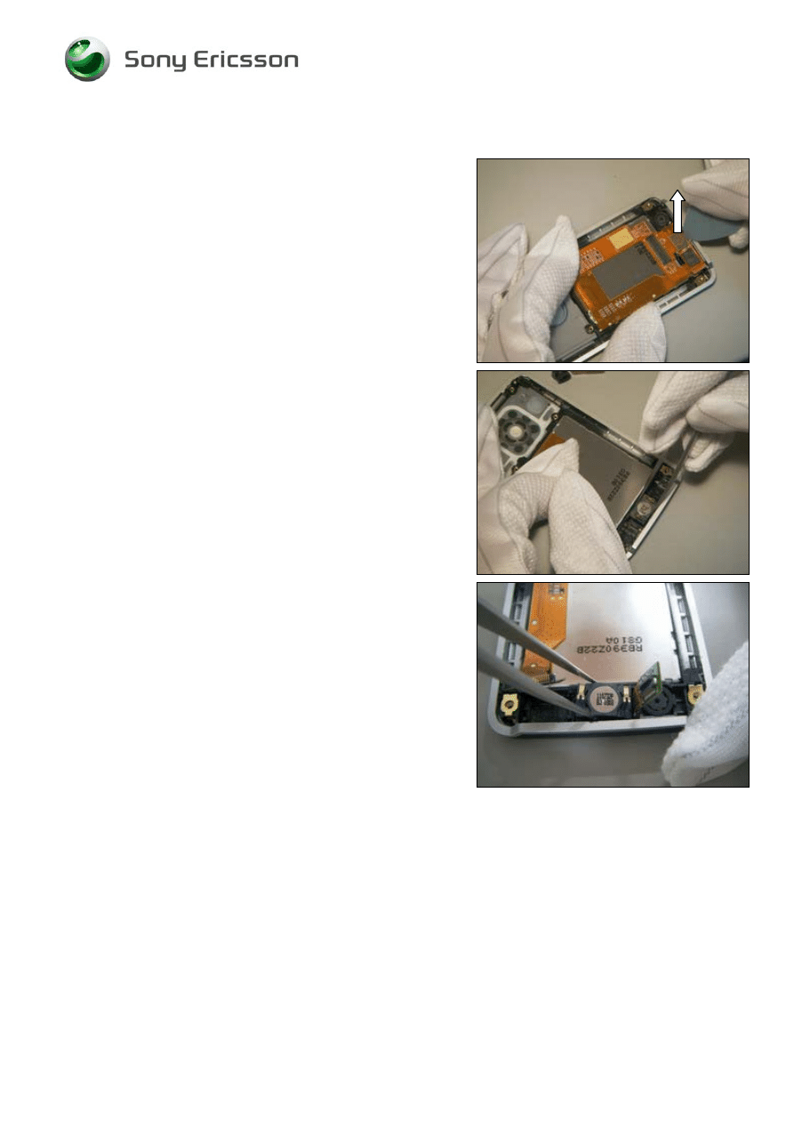
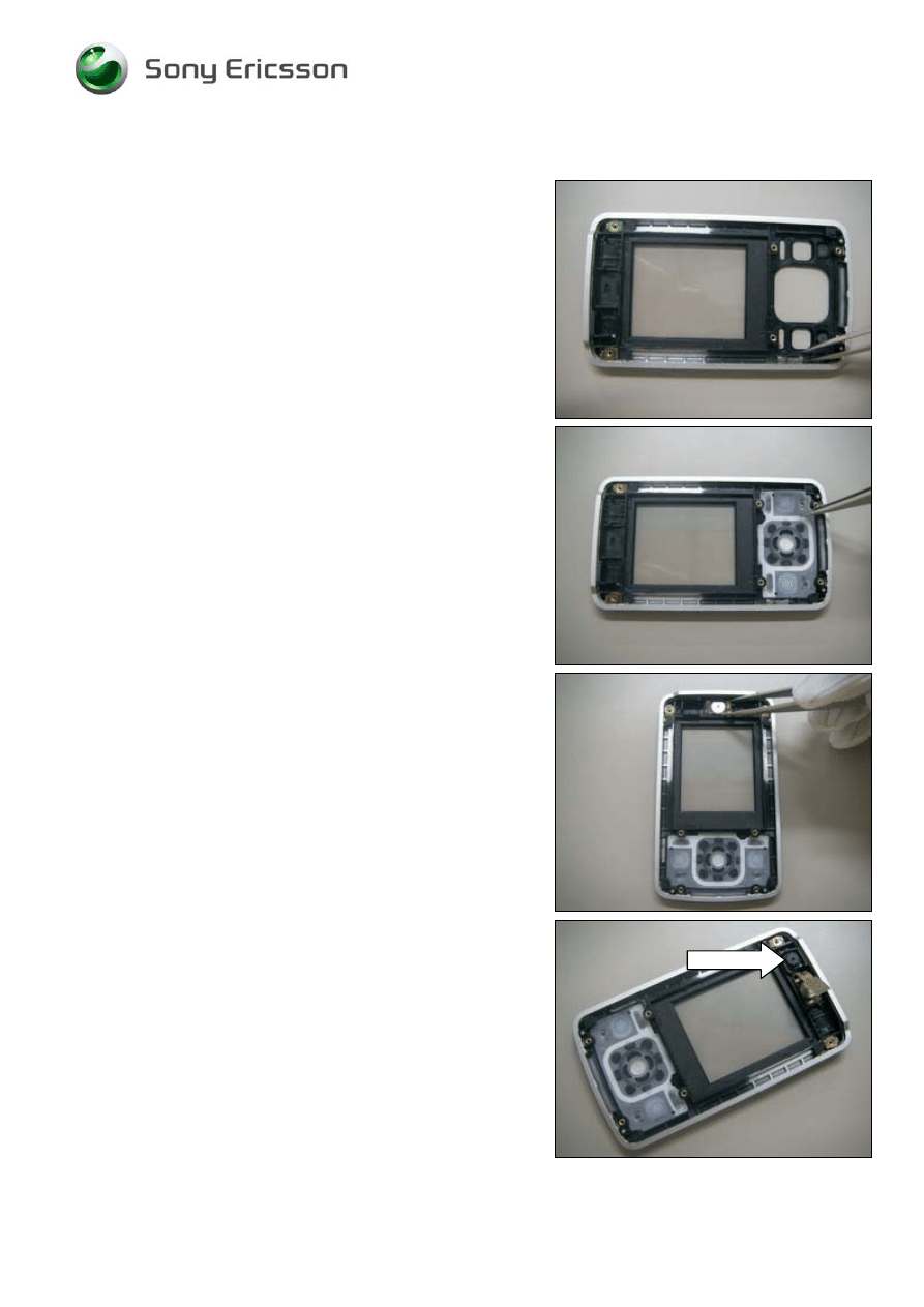
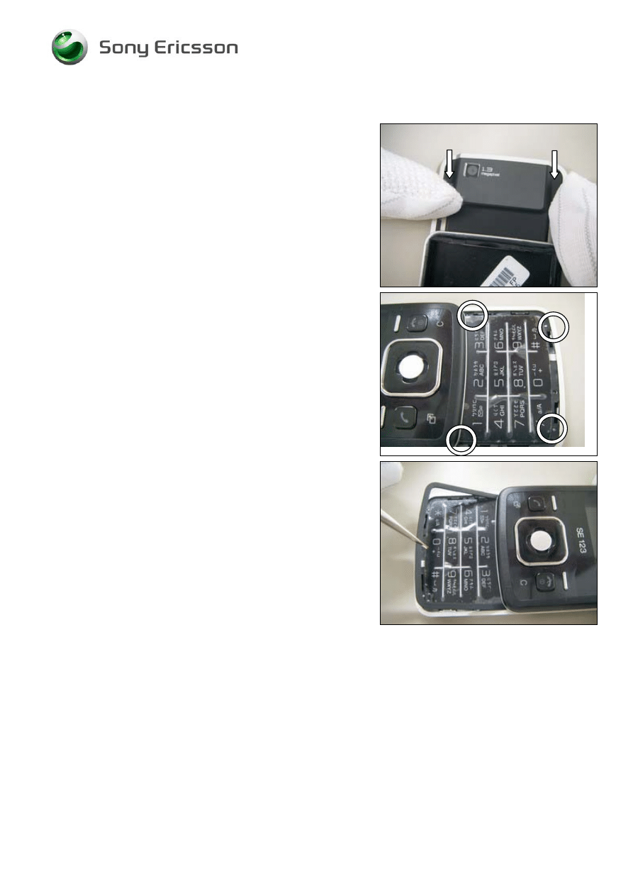
2.1.3 PCB
Use the Guitar pick to release the connector for the Main
Keyboard FPC assy.
Use the Guitar pick to lift up the Main Keyboard FPC assy.
Use the Guitar pick to lift up and remove main PCB
©
Sony Ericsson Mobile Communications AB
Working Instruction, Mechanical
1212-9365 Rev 1
10(42)
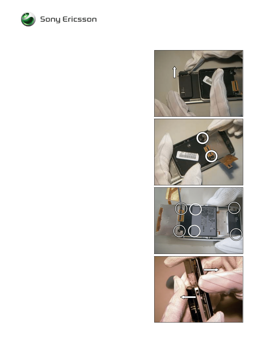
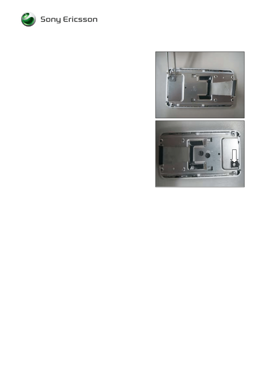
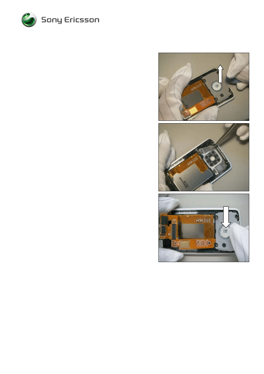
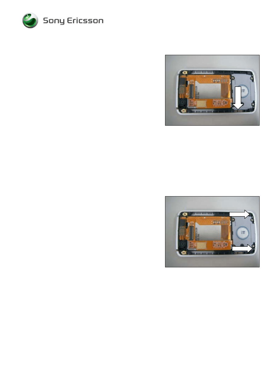
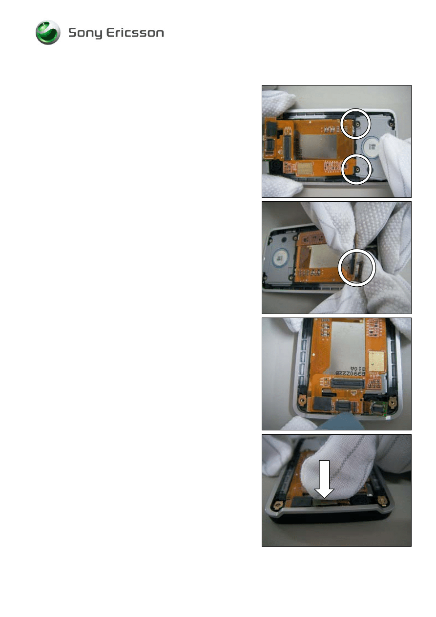
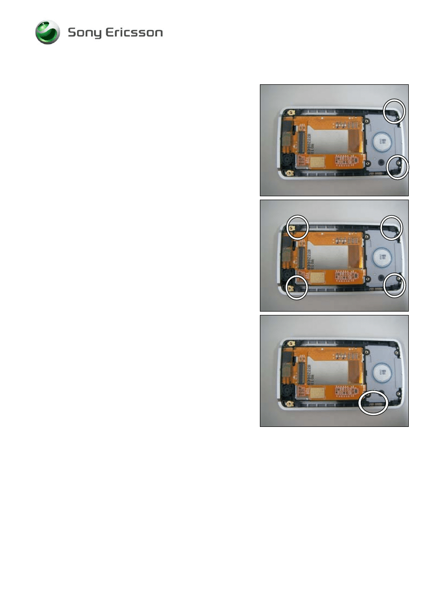
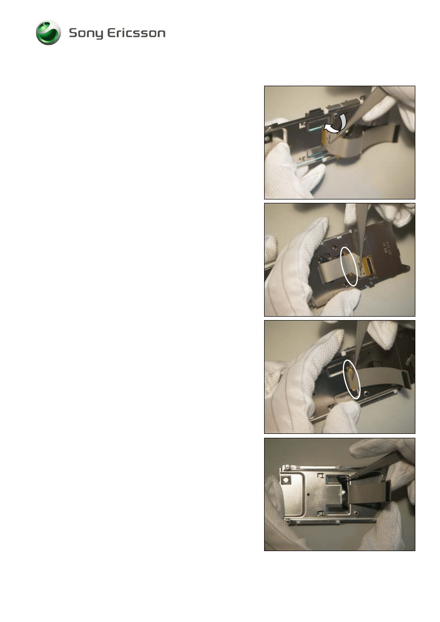
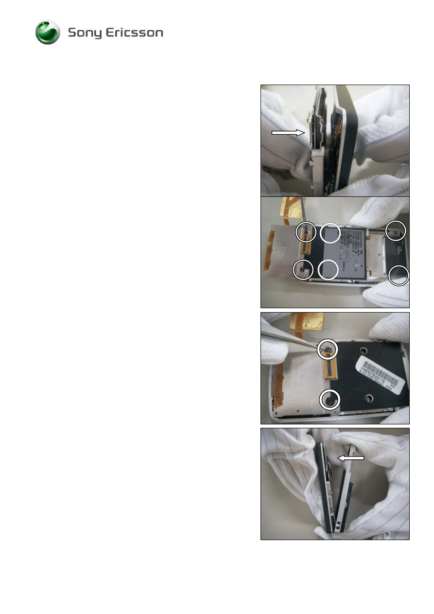
2.1.4 Rear
Cover
Assy
Use a pair of tweezers to remove the Top Rear Cover
Use a pair of tweezers to remove the screw mylars
Release the six screws
NOTE!
You must slide the phone half-ways to access two of the
screws
Use your fingers to separate the Front Cover Assy and the
Rear Cover Assy.
©
Sony Ericsson Mobile Communications AB
Working Instruction, Mechanical
1212-9365 Rev 1
11(42)
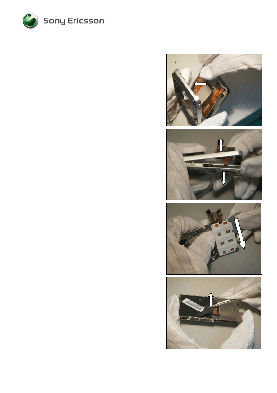
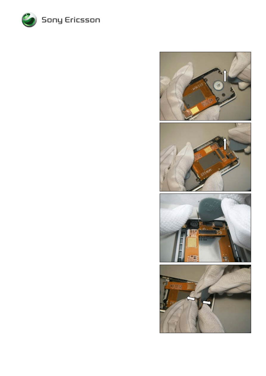
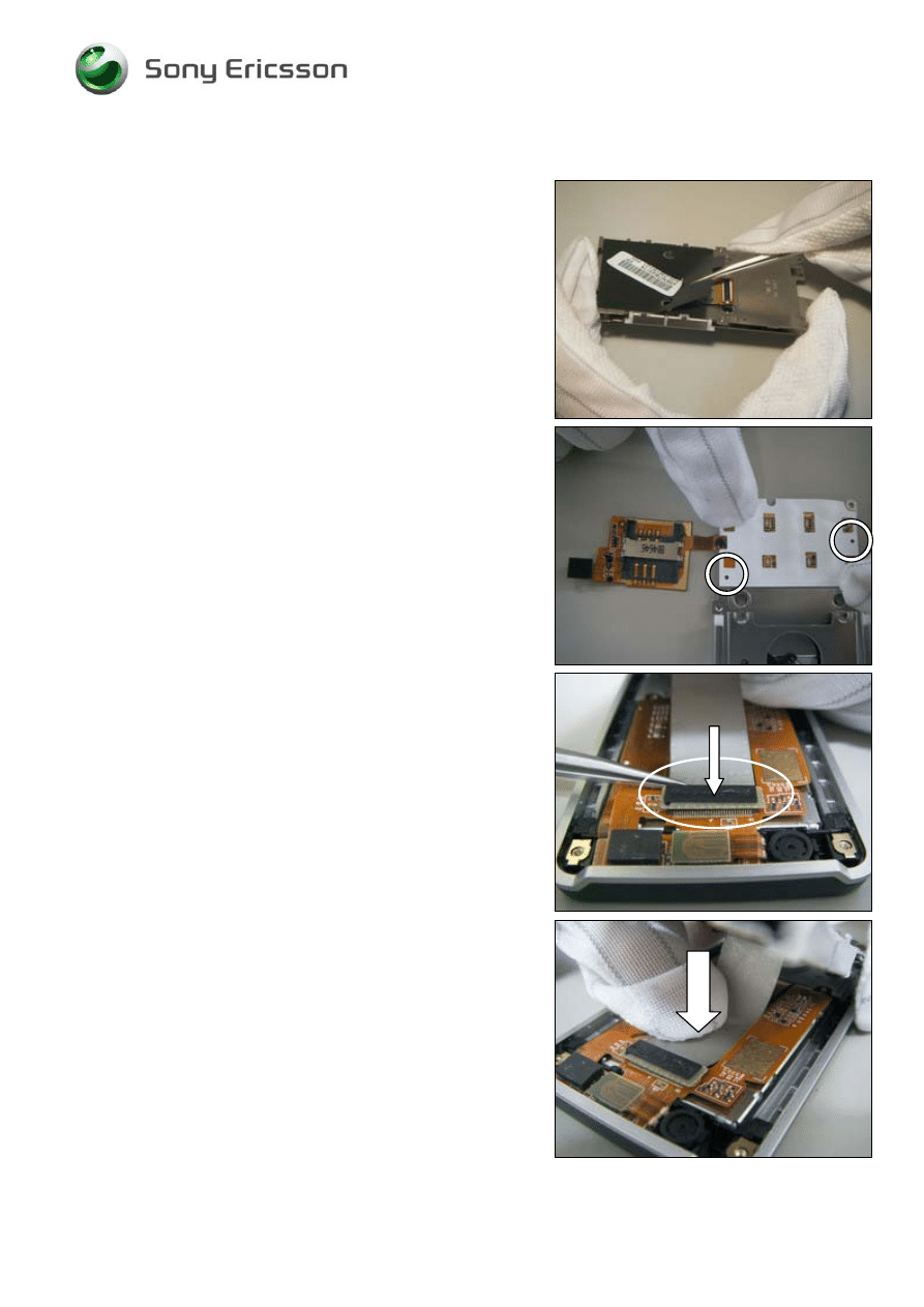
2.1.5 Slide
Hinge
Assy
D
O NOT DAMAGE THE
FPC
CONNECTOR
!
Use the guitar pick to release the connector for the Hinge
FPC Assy.
Use you finger to separate Slide Hinge Assy from Rear
Cover Assy
Use the guitar pick to remove the main key dome assy.
Use a pair of tweezers to remove the black cover mylar
from the slide hinge module
©
Sony Ericsson Mobile Communications AB
Working Instruction, Mechanical
1212-9365 Rev 1
12(42)
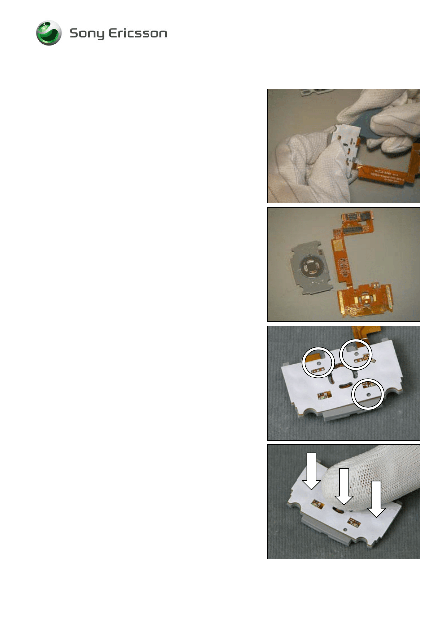
Slide Hinge Assy continued
Use a pair of tweezers to remove the Mylar Hinge FPC from
the Slide Hinge Assy.
T
HERE IS ADHESIVE UNDER THE
H
INGE
FPC
A
SSY
!
Use a pair of tweezers to separate the hinge FPC.
Use a pair of tweezers to separate the Hinge FPC on the
other side.
Use a pair of tweezers to pull out the Hinge FPC Assy
©
Sony Ericsson Mobile Communications AB
Working Instruction, Mechanical
1212-9365 Rev 1
13(42)
2.1.6 Function Key FPC Assy
Use the guitar pick to pick up the Loudspeaker Box from the
Front Cover Assy.
Use the guitar pick to release the camera FPC connector
from Function Key FPC Assy.
Use the guitar lift up function key FPC from the upper side.
Use the guitar pick to separate the Function Key FPC Assy
from the Display and the Front Cover Assy.
©
Sony Ericsson Mobile Communications AB
Working Instruction, Mechanical
1212-9365 Rev 1
14(42)
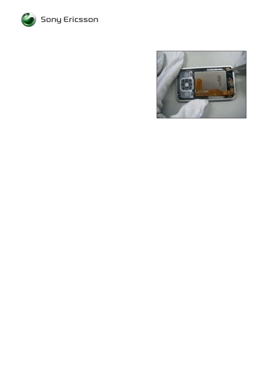
2.1.7 Display
128x160
TFT
D
O NOT TOUCH THE
LCD
SURFACE
!
Use a pair of tweezers to remove display module from the
Front Cover Assy.
©
Sony Ericsson Mobile Communications AB
Working Instruction, Mechanical
1212-9365 Rev 1
15(42)
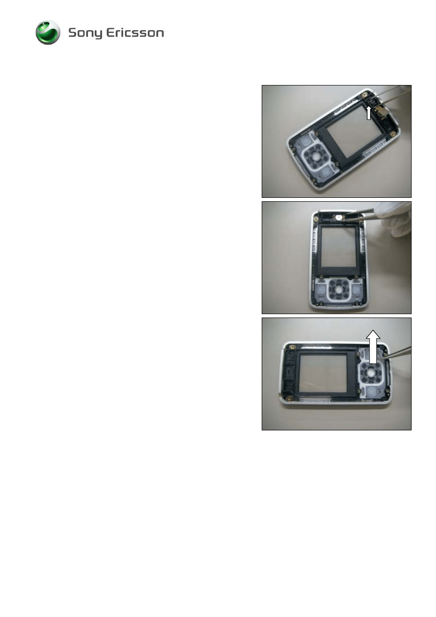
2.1.8 Front
Cover
Assy
B
E CAREFUL WITH THE TWEEZERS NOT TO DAMAGE THE
CAMERA SOCKET
!
Use a pair of tweezers to remove the Camera
Remove the Ear Speaker from the cavity.
Use a pair of tweezers to pick up the Function
Keyboard from the Front Cover Assy.
©
Sony Ericsson Mobile Communications AB
Working Instruction, Mechanical
1212-9365 Rev 1
16(42)
3 Replacements
Search for the part to be replaced on the Contents page and go to that instruction to be found in this
Replacements section.
The instruction usually begins by directing you to the Disassembly section with a specification of the
instructions you have to carry out in order to disassemble the phone as far as needed before the
actual replacement.
Go back to this Replacements section and carry out the instruction.
The instruction usually ends by directing you to the Reassembly section with a specification of the
instructions you have to carry out in order to reassemble the phone.
Start
DISASSEMBLY
REASSEMBLY
Contents
page
REPLACEMENTS
Done
©
Sony Ericsson Mobile Communications AB

Working Instruction, Mechanical
1212-9365 Rev 1
17(42)
3.1 Battery
Cover
Follow the 2.1.1 Disassembly instructions!
Prepare the new Battery Cover.
Follow the 4.1.8 Reassembly instructions!
3.2 Bottom Cover U-Shape
Follow the 2.1.2 Disassembly instructions!
Prepare the new Bottom Cover U-Shape
Follow the 4.1.7 – 4.1.8 Reassembly instructions!
3.3 Keyboard
Follow the 2.1.1 – 2.1.2 Disassembly instructions!
Prepare a new Keyboard
Follow the 4.1.7 – 4.1.8 Reassembly instructions!
3.4 Rear
Cover
Assy
Follow the 2.1.1 – 2.1.4 Disassembly instructions!
Prepare a new Rear Cover Assy
Follow the 4.1.5 – 4.1.8 Reassembly instructions!
3.5 Function Key FPC Assy
Follow the 2.1.1 – 2.1.5 Disassembly instructions!
Prepare a new Function Key FPC Assy
Follow the 4.1.3– 4.1.8 Reassembly instructions!
3.6 Top Rear Cover
Follow the 2.1.5 Disassembly instructions!
Prepare a new Top Rear Cover
Follow the 4.1.7 Reassembly instructions!
3.7 Display 128x160 TFT
Follow the 2.1.1 – 2.1.6 Disassembly instructions!
Prepare a new Display
Follow the 4.1.2 – 4.1.8 Reassembly instructions!
Company Internal
©
Sony Ericsson Mobile Communications AB

Working Instruction, Mechanical
1212-9365 Rev 1
18(42)
3.8 Slide
Hinge
Assy
Follow the 2.1.1 – 2.1.5 Disassembly instructions!
Prepare a new Slide Hinge Assy
Follow the 4.1.4 – 4.1.8 Reassembly instructions!
3.9 Hinge
FPC
Assy
Follow the 2.1.1 – 2.1.5 Disassembly instructions!
Prepare a new Hinge FPC Assy
Follow the 4.1.4 – 4.1.8 Reassembly instructions!
3.10 Camera 1.3 MPixel CMOS
Follow the 2.1.1 – 2.1.8 Disassembly instructions!
Prepare a new Camera 1.3 MPixel CMOS
Follow the 4.1.1 – 4.1.8 Reassembly instructions!
3.11 Damper Camera
Follow the 2.1.1 – 2.1.8 Disassembly instructions!
Prepare a new Damper Camera
Follow the 4.1.1 – 4.1.8 Reassembly instructions!
3.12 Magnet
Follow the 2.1.1 – 2.1.8 Disassembly instructions!
Prepare a new Magnet
Follow the 4.1.1 – 4.1.8 Reassembly instructions!
©
Sony Ericsson Mobile Communications AB
Working Instruction, Mechanical
1212-9365 Rev 1
19(42)
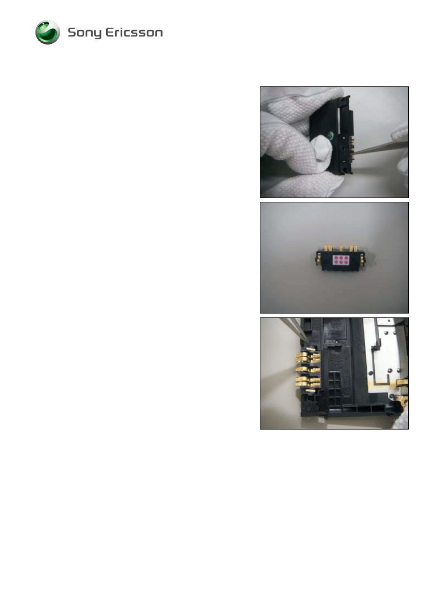
3.13 Battery Connector 5pin & Liquid Intrusion Indicator
Follow the 2.1.1 – 2.1.2 Disassembly instructions!
Use a pair of tweezers to remove Battery Connector &
Liquid Intrusion Indicator from Antenna cover.
D
O NOT REUSE THE
L
IQUID
I
NTRUSION
I
NDICATOR
!
Prepare the new Battery Connector & Liquid Intrusion
Indicator.
Assemble the new Battery Connector & Liquid Intrusion
Indicator into the antenna cover Assy cavity by using a pair
of tweezers.
Press the connector to the bottom of the cavity.
Follow the 4.1.7 – 4.1.8 Reassembly instructions!
©
Sony Ericsson Mobile Communications AB
Working Instruction, Mechanical
1212-9365 Rev 1
20(42)
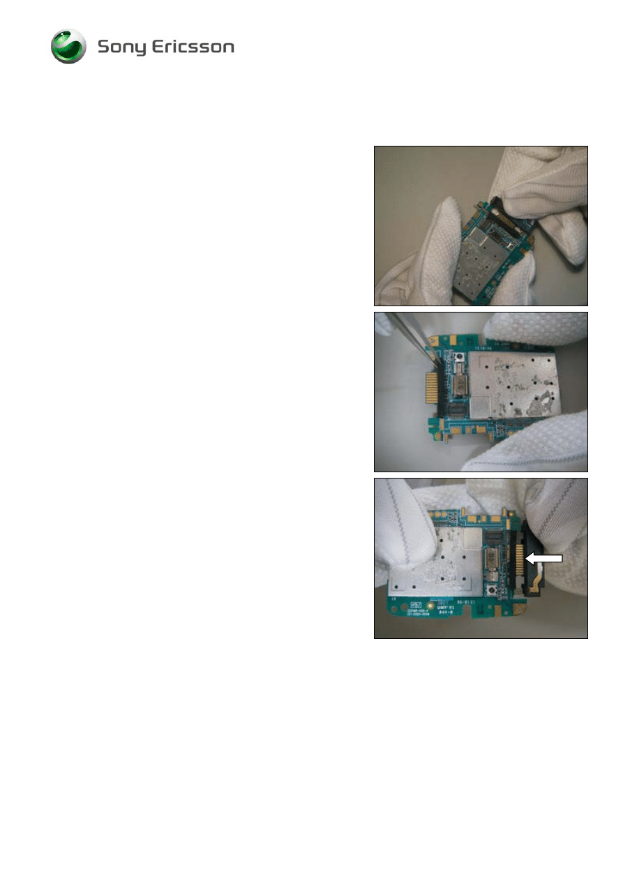
3.14 System Connector BT Antenna & System Connector
Sponge
Follow the 2.1.1 – 2.1.3 Disassembly instructions!
Use your fingers to pull out the System Connector BT
Antenna from main PCB.
Remove the System Connector Sponge using a pair of
tweezers.
Prepare the new System Connector BT Antenna & System
Connector Sponge.
Use a pair of tweezers to assemble the System Connector
sponge.
Use your fingers to assemble the System Connector BT
Antenna.
Follow the 4.1.6 – 4.1.8 Reassembly instructions!
©
Sony Ericsson Mobile Communications AB
Working Instruction, Mechanical
1212-9365 Rev 1
21(42)
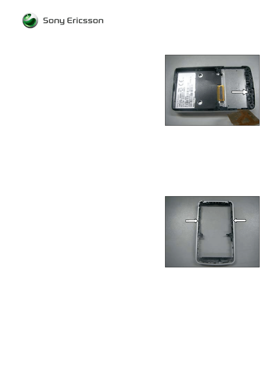
3.15 Microphone Sponge Dust Net
Follow the 2.1.1 – 2.1.3 Disassembly instructions!
Use a pair of tweezers to tear off the Microphone Sponge
Dust Net.
Prepare the new Microphone Sponge Dust Net.
Follow the 4.1.6 – 4.1.8 Reassembly instructions!
3.16 Anti-Friction Block
Follow the 2.1.1 – 2.1.3 Disassembly instructions!
Use a pair of tweezers to remove the Anti-Friction from the
rear cover according to indicate by the arrows of the picture.
Prepare the new Anti-Friction.
Follow the 4.1.6 – 4.1.8 Reassembly instructions!
©
Sony Ericsson Mobile Communications AB
Working Instruction, Mechanical
1212-9365 Rev 1
22(42)
3.17 Main Keypad FPC Assy
Follow the 2.1.1 – 2.1.5 Disassembly instructions!
Use the guitar pick to remove the old Main Keypad
FPC Assy.
Prepare the new Main Keypad FPC Assy.
U
SE THE LOCATION HOLES TO ALIGN THE DOME SHEET
!
Use your fingers to paste the new Main Keypad FPC
Assy.
Follow the 4.1.6 – 4.1.8 Reassembly instructions!
Company Internal
©
Sony Ericsson Mobile Communications AB
Working Instruction, Mechanical
1212-9365 Rev 1
23(42)
3.18 Function Key FPC Assy & Loudspeaker Box 38.5x19
Follow the 2.1.1 – 2.1.6 Disassembly instructions!
Use the guitar pick to slide off the function key metal dome
from speaker box FPC.
Prepare a new Function Key FPC Assy and/or Loudspeaker
Box
Align the position holes for the Function Key dome sheet
with the Loudspeaker Box
Press down the Function Key dome sheet to fixate the
adhesive.
Follow the 4.1.3 – 4.1.8 Reassembly instructions!
©
Sony Ericsson Mobile Communications AB
Working Instruction, Mechanical
1212-9365 Rev 1
24(42)
3.19 Camera Window
Follow the 2.1.1 – 2.1.5 Disassembly instructions!
Use a pair of tweezers to remove the camera window and
clean surface from adhesive.
Prepare the new Camera window and Camera Lens
adhesive.
Y
OU MUST USE NEW
C
AMERA
L
ENS ADHESIVE
!
Mount the camera lens adhesive and then press down the
Camera Window.
Follow the 4.1.4 – 4.1.8 Reassembly instructions!
©
Sony Ericsson Mobile Communications AB
Working Instruction, Mechanical
1212-9365 Rev 1
25(42)
3.20 Plating Camera Sheet
Use a pair of tweezers to remove the Top Rear Cover
Remove the Plating Camera Sheet and clean all adhesive
residues from the Slide Hinge Assy
Prepare a new Plating Camera Sheet and mount it onto the
Slide Hinge Assy
Align the Top Rear Cover to the upper Hinge Slide Assy
and press it gently until it is mounted properly.
©
Sony Ericsson Mobile Communications AB
Working Instruction, Mechanical
1212-9365 Rev 1
26(42)
3.21 Ear Speaker 11.0x7.0 Rectangular
Follow the 2.1.1 – 2.1.5 Disassembly instructions!
Use the guitar pick to release the camera FPC connector
from Function Key FPC Assy.
Use a pair of tweezers to lift up and remove the old
Earphone Speaker.
Prepare the new Ear Speaker.
D
ON
’
T TOUCH THE CONTACT SPRINGS
!
Gently press down the Earphone Speaker to the bottom of
the cavity.
Follow the 4.1.4 – 4.1.8 Reassembly instructions!
©
Sony Ericsson Mobile Communications AB
Working Instruction, Mechanical
1212-9365 Rev 1
27(42)
3.22 Function Keyboard
Follow the 2.1.1 – 2.1.5 Disassembly instructions!
Use the guitar pick to pick up the Loudspeaker Box from the
Front Cover Assy.
Use a pair of tweezers to pick up Function Keyboard form
the Front Cover Assy.
Prepare the new Function Keyboard.
Use your fingers to assemble the Loudspeaker Box into the
front cover Assy. Make sure it fits properly.
Follow the 4.1.4 – 4.1.8 Reassembly instructions!
©
Sony Ericsson Mobile Communications AB
Working Instruction, Mechanical
1212-9365 Rev 1
28(42)
3.23 Magnet
Follow the 2.1.1 – 2.1.5 Disassembly instructions!
Use a pair of tweezers to remove the magnet from the front
cover.
Prepare the new magnet and insert it into the groove.
Follow the 4.1.4 – 4.1.8 Reassembly instructions!
3.24 Conductive Rubber & Damper Stopper
Follow the 2.1.5 – 2.1.8 Disassembly instructions!
Use a pair of tweezers to pick up Conductive Rubbers
Prepare new conductive rubbers and insert them into the
cavities
Follow the 4.1.4 – 4.1.8 Reassembly instructions!
©
Sony Ericsson Mobile Communications AB
Working Instruction, Mechanical
1212-9365 Rev 1
29(42)
3.25 Damper Stopper
Follow the 2.1.5 – 2.1.8 Disassembly instructions!
Use a pair of tweezers to pick up Damper Stoppers.
Prepare new Damper Stoppers and insert them into the
cavities
Follow the 4.1.4 – 4.1.8 Reassembly instructions!
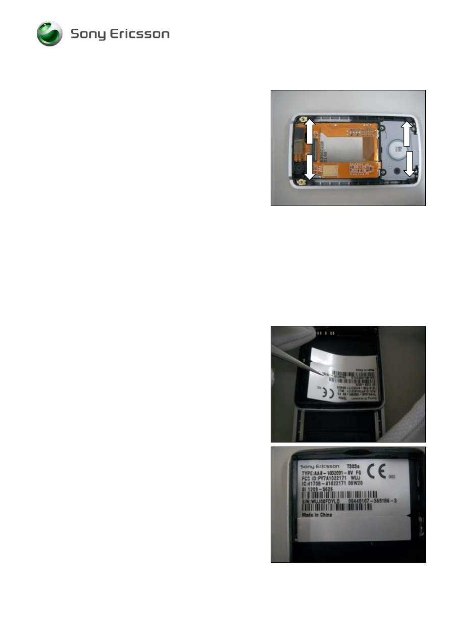
3.26 KRH Label
Follow the 2.1.1 Disassembly instructions!
Read the old label and/or write the information into the
“Label make” program before removal
Note the position of the label before removal
Heat up the label by using hot air, if needed.
Carefully remove the label without causing scratches
If there still are residues, clean the surface with isopropyl
alcohol
Check that the proper label format is loaded in the Zebra
printer.
Write a new label by using the program “Label make” and
check that the printing is OK.
Take the new label and place it onto the frame as in the
adjacent picture.
O
NE LABEL ONLY IS ALLOWED
!
Follow the 4.1.8 Reassembly instructions!
©
Sony Ericsson Mobile Communications AB
Working Instruction, Mechanical
1212-9365 Rev 1
30(42)
4 Reassembly
After replacing a part being listed in Replacements, the instruction of that section usually ends by
directing you to this Reassembly section with a specification of the instructions you have to carry out
in order to reassemble the phone.
Start
DISASSEMBLY
REASSEMBLY
Contents
page
REPLACEMENTS
Done
4.1 Overview
The reassembly is done in the following sequence:
1. Front Cover Assy
2. Display 128x160 TFT
3. Function Key FPC Assy
4. Slide Hinge Assy
5. Rear Cover Assy
6. PCB
7. Antenna Cover
8. Battery Cover (a) & Battery (b)
©
Sony Ericsson Mobile Communications AB
Working Instruction, Mechanical
1212-9365 Rev 1
31(42)
4.1.1 Front
Cover
Assy
Insert the magnet into the front cover.
Assemble the function keyboard to the front cover.
Insert the Ear speaker to the cavity.
Mount the Camera 1.3 MPixel CMOS and Damper Camera
Company Internal
©
Sony Ericsson Mobile Communications AB

Working Instruction, Mechanical
1212-9365 Rev 1
32(42)
4.1.2 Display
128x160
TFT
Assemble the display 128x160 TFT.
©
Sony Ericsson Mobile Communications AB
Working Instruction, Mechanical
1212-9365 Rev 1
33(42)
4.1.3 Function Key FPC Assy
Use your fingers to assemble the Loudspeaker Box into the
front cover Assy. Make sure it fits properly.
Use your fingers to press down the connector.
Use your fingers to press down the Function Key FPC into
cavity properly.
Use your fingers to press down the camera FPC into
connector properly.
©
Sony Ericsson Mobile Communications AB
Working Instruction, Mechanical
1212-9365 Rev 1
34(42)
Function Key FPC Assy continued
NOTE!
Make sure that the two conductive rubbers are mounted
before you continue.
NOTE!
Make sure that the four damper rubbers are mounted
before you continue.
NOTE!
Make sure that the magnet is mounted before you continue.
The mark line should be visible.
©
Sony Ericsson Mobile Communications AB
Working Instruction, Mechanical
1212-9365 Rev 1
35(42)
4.1.4 Slide
Hinge
Assy
P
AY CAREFUL ATTENTION TO THE DIRECTION OF HINGE
FPC.
Use a pair of tweezers to assemble the hinge FPC into the
Slide hinge assy.
P
AY ATTENTION TO ALIGN THE POSITION POINTS
!
Use a pair of tweezers to paste the hinge FPC onto the
Slide hinge assy with adhesive.
P
AY ATTENTION TO ALIGN THE POSITION POINTS
!
Use a pair of tweezers to paste the hinge FPC onto the
back slide hinge assy with adhesive.
Use a pair of tweezers to mount the
Mylar Hinge FPC
.
©
Sony Ericsson Mobile Communications AB
Working Instruction, Mechanical
1212-9365 Rev 1
36(42)
Slide Hinge Assy continued
U
SE A NEW
M
YLAR
B
ATTERY
L
ABEL
!
Use a pair of tweezers to mount the Mylar Battery Label.
P
AY ATTENTION TO ALIGN THE POSITION POINTS
!
Use your fingers to paste the main keypad FPC Assy.
Use a pair of tweezers to fix the slide hinge FPC, and then
press slide hinge FPC into Function key connector with your
fingers.
Press and paste adhesive of the slide hinge onto display
back surface
©
Sony Ericsson Mobile Communications AB
Working Instruction, Mechanical
1212-9365 Rev 1
37(42)
4.1.5 Rear
Cover
Assy
Assemble the Slide Hinge Assy with the Front Cover Assy
together.
Use Torque screwdriver to tighten the 6 screws
NOTE!
Screw torque set to 9 Ncm
U
SE NEW
S
CREW
H
INGE
M
YLARS
!
Use a pair of tweezers to mount the Screw Mylars.
Assemble the Rear cover Assy with the slide hinge Assy
together.
©
Sony Ericsson Mobile Communications AB
Working Instruction, Mechanical
1212-9365 Rev 1
38(42)
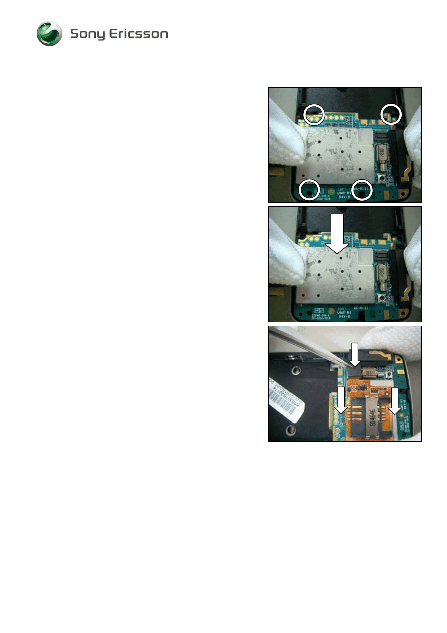
4.1.6 PCB
A
TTENTION
4
POSITION HOLES FOR LOCATING AND MAKE SURE
THEY FIT PROPERLY
!
Use your fingers to press main PCB into the rear cover
Assy.
Press down to connect the PCB with the Hinge FPC Assy
Gently assemble the main key FPC connector to main PCB
Press down the Main keypad FPC Assy connector.
©
Sony Ericsson Mobile Communications AB
Working Instruction, Mechanical
1212-9365 Rev 1
39(42)
4.1.7 Antenna
Cover
Use your fingers to assemble the Antenna Cover.
Use Torque screwdriver to tighten the two screws
NOTE!
Torque set to 10 Ncm
Use Torque screwdriver to tighten the two screws
NOTE!
Torque set to 10 Ncm
Assemble Top Rear Cover to Slide hinge Assy.
Company Internal
©
Sony Ericsson Mobile Communications AB
Working Instruction, Mechanical
1212-9365 Rev 1
40(42)
Antenna Cover continued
Press down Top Rear Cover and make sure it fit properly.
Align the Main keypad using position holes and press
gently.
Assemble Bottom Cover U-Shape and make sure there are
no gaps
©
Sony Ericsson Mobile Communications AB
Working Instruction, Mechanical
1212-9365 Rev 1
41(42)
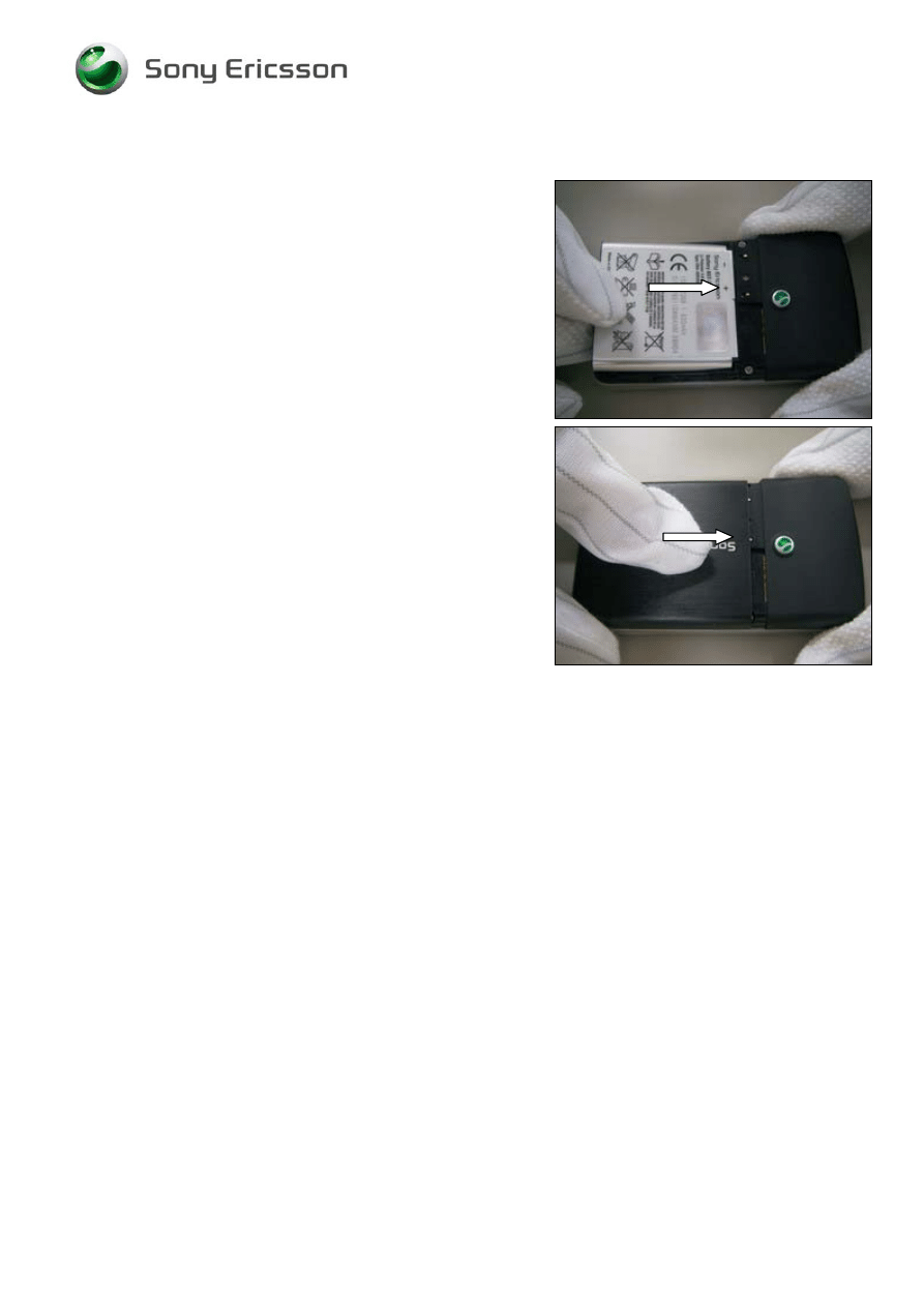
4.1.8 Battery Cover & Battery
Install the battery.
Install the battery cover.
©
Sony Ericsson Mobile Communications AB
Working Instruction, Mechanical
1212-9365 Rev 1
42(42)
5 Revision history
Rev.
Date
Changes / Comments
1 2008-07-10 1
st
release
2
2008-07-15
Due to system problem. No changes in content.
©
Sony Ericsson Mobile Communications AB
Document Outline
Wyszukiwarka
Podobne podstrony:
Sony Ericsson T610 instrukcja rozbiórki
Sony Ericsson T100 T105 instrukcja rozbiórki
Instrukcja obsługi telefonu Sony Ericsson K610i
Instrukcja Sony Ericsson W595
sony ericsson k770 installation instruction, mechanical
sony ericsson k770 test instruction, mechanical
Sony Ericsson GC79, TELEFONIA, Opisy telefonów
sony-ericsson, Analiza finasowa
sony-ericsson, PODSTAWY ZARZĄDZANIA
problemy Sony Ericsson
simlock, Telefony, SONY ERICSSON, C510
Sony Ericsson GC79, TELEFONIA, Opisy telefonów
sony ericsson k770 equipment list, mechanical
Sony Ericsson W910i EN
Sony Ericsson wprowadza dwa nowe modele W508 i C510
sony ericsson k770 part list, mechanical
Jak odzyskać usunięte smsy z telefonu sony ericsson xperia
Jak odzyskać smsy z telefonu sony ericsson
więcej podobnych podstron