r control surfaces can be packing
hinges. I prefer robart hinge
d in place for the added longivity
eeness. CA hinges work well also.

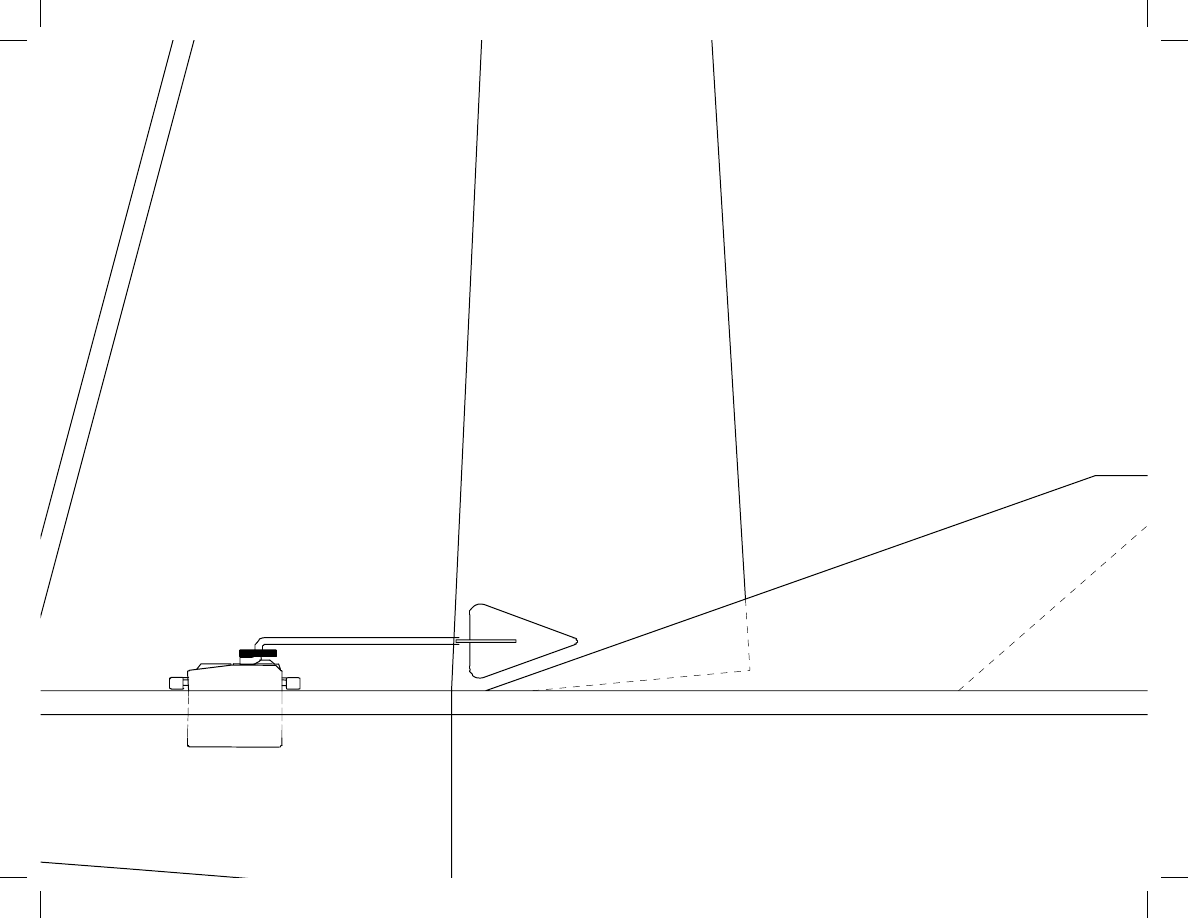
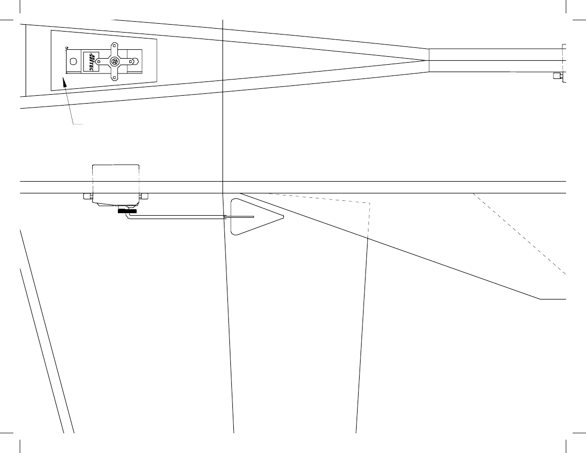
Function Rudders Optional
HS-
56HB
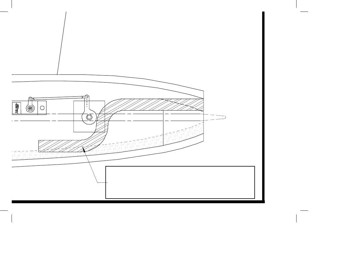
Laser cut 1/4" birch motor block.
Epoxy into plane. DO NOT use
CA on the moutor mount.

All hinging for
tape or actual
points epoxied
and control fre
HS-
56HB
Optional Rudder
Servo Location

HS-
5
6HB
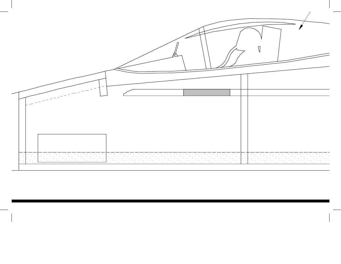
Cut hatch after painting
for radio access
ww.3DFoamy.com
Standard F-18 Hornet

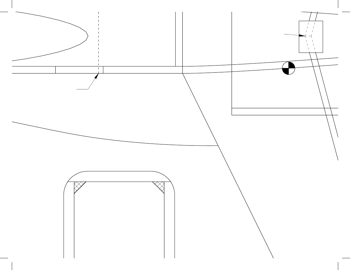
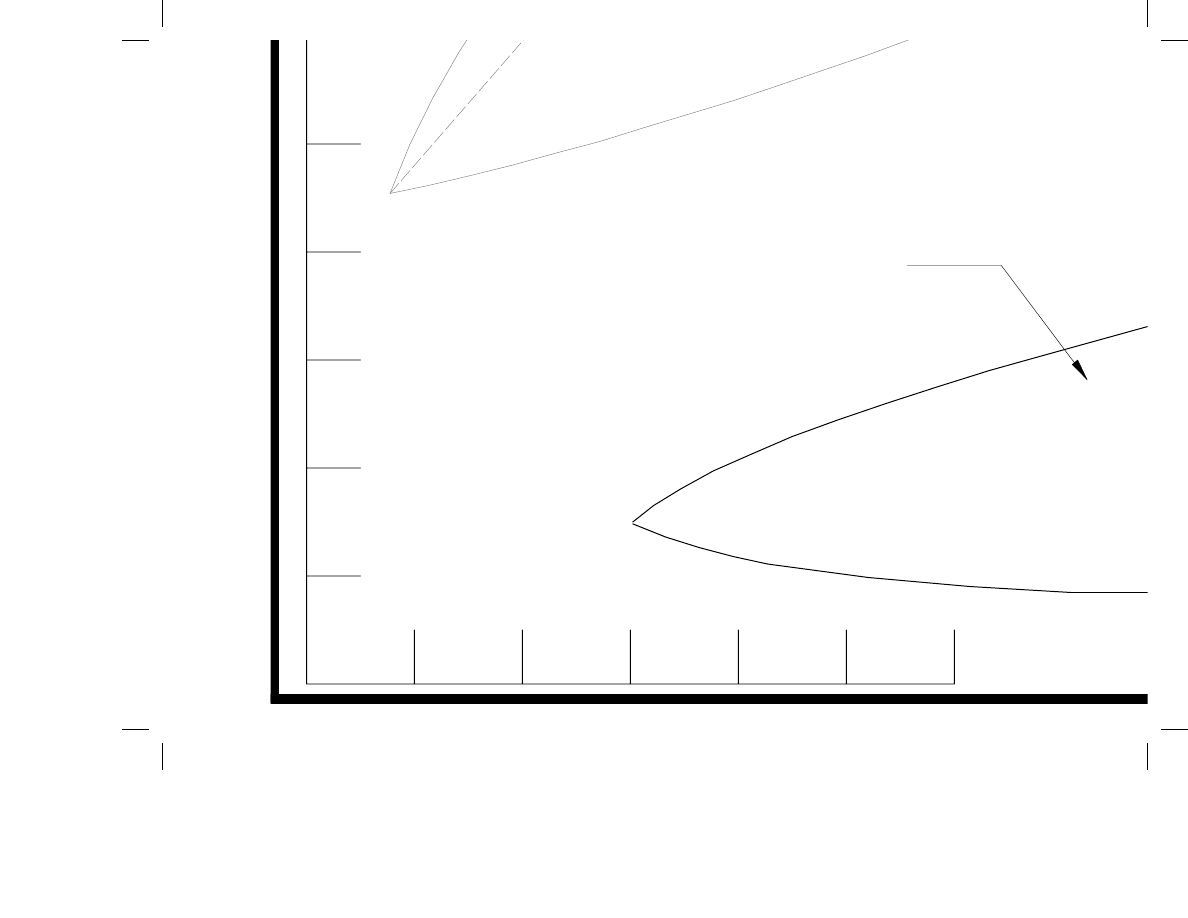
Cut a "V" groove
in foam for
spars. Pull spar
through groove
to make round
Start with the recomended
CG INFO

SC
se:
minute epoxy for the main
ot strongenough, and will crack
CG Range 3-3.5
F-3
Start with the recomended
CG range. You can adjust it
further back as you become
more familiar with the jet.
f Canopy Frame
1/8" Ply
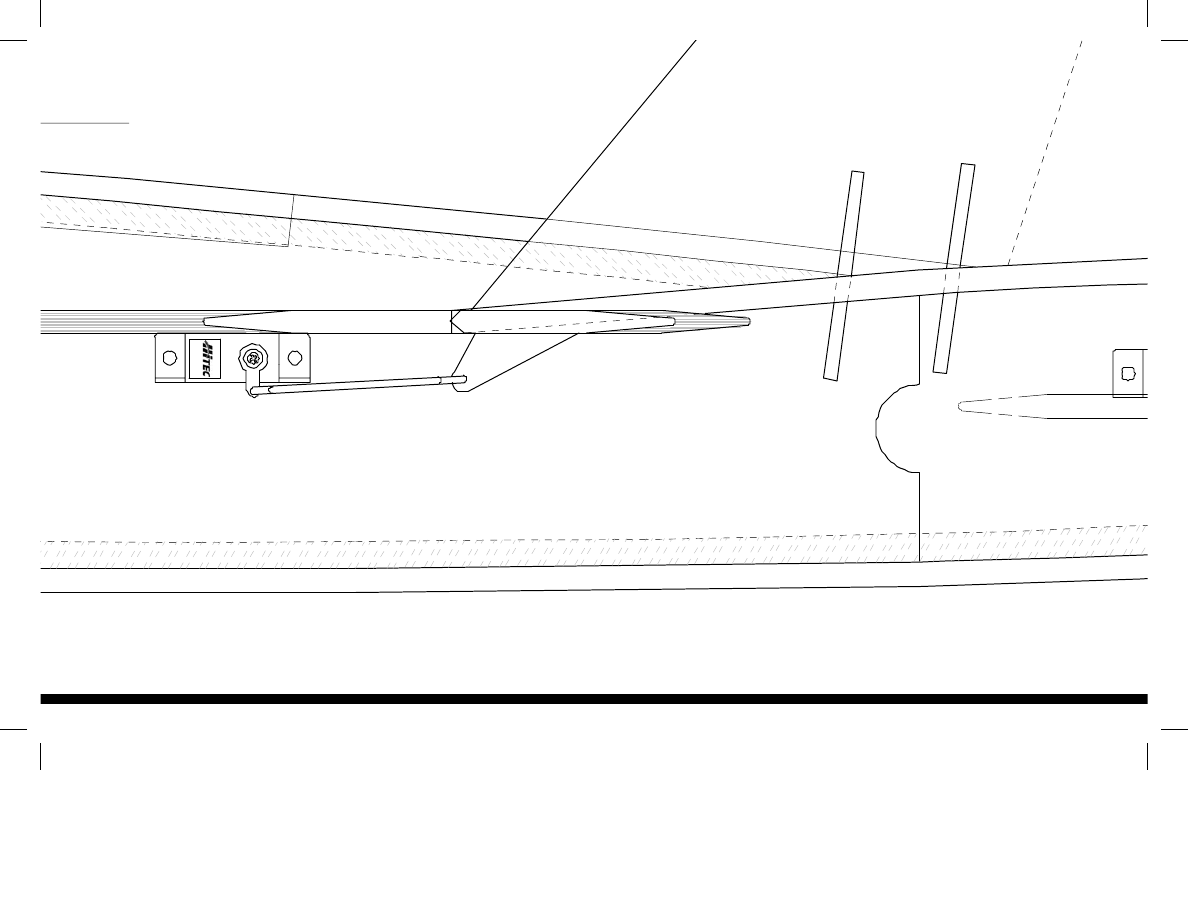
Spar Cap
(Both sides)
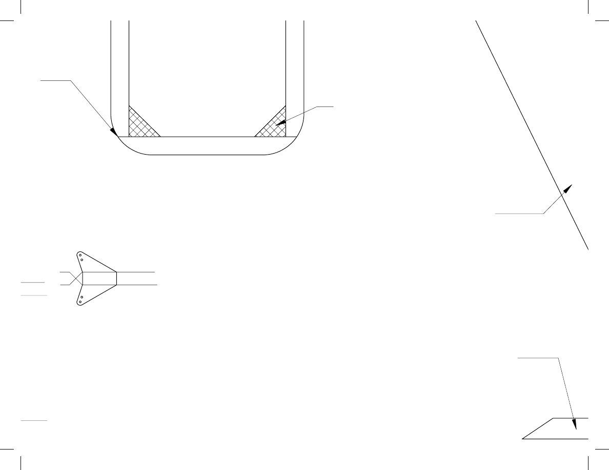
1/4 x 3/8 Balsa Missle Rails
Pull Pull
Pull
ontrol horns from 1/32"
a plastic coffee can lid.
Round LE, apply 3M 1" Satin tape for protection
nd
er,
400
Dow EPS foam tristock
Vacuum Formed Canopy
(Sand from foam if scratch built)
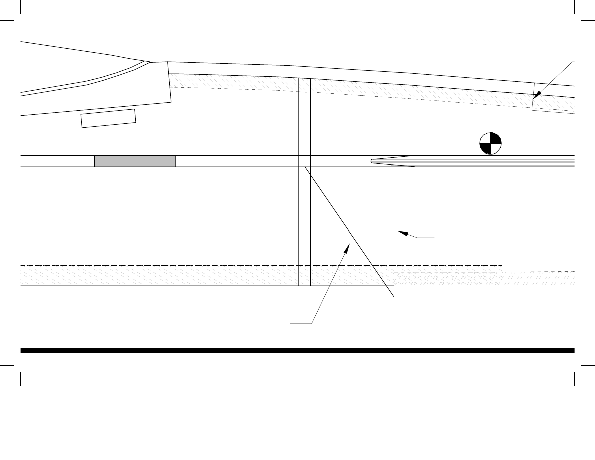
Leave intake here for The Super Hornet
F-3
Strake Tab
ww
Cut Intake here for S
CG

Wing area: 275 sq in (effective area, which includes the effect of the wing strakes)
pan: 28.4 in
ength: 41.7 in
Weight RTF: 15.6 oz as shown
Wing loading: 8.2 oz/ft2 (based on effective wing area)
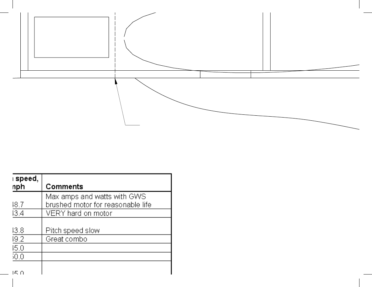
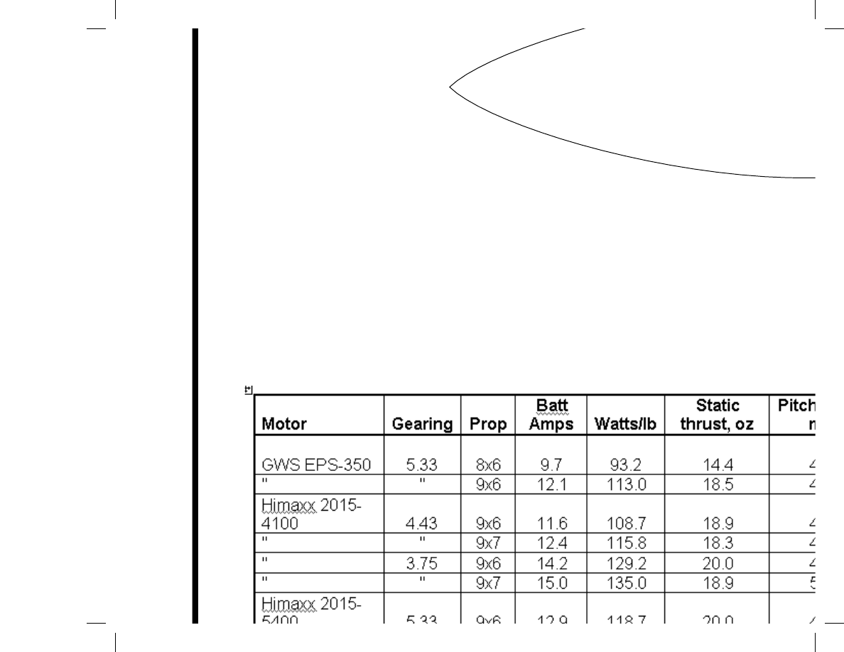
otor: GWS EPS-350 with “C” gearing
attery: 11.1V 1200 mAh Lipo
rop: GWS 8x6 SF
rototype Setup/Specs
© 2004 3DFoamy.com.
s reserved.
and Drawn by:
mate & Levi Jordan
0/19/2004
rk Jet

F-1
F-2
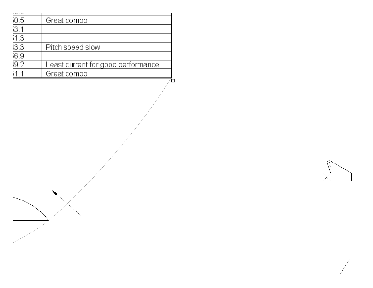
urrent draw: 9.7 amps
ower loading: 101 watts/lb
adio equipment: GWS R-6 receiver, GWS Pico and Hitec HS-55 servos, 10 amp ES
ight controls: Wing flaperons, full-flying horizontal stabilizer, twin rudders
aterials used: Either 6mm Depron or BlueCore fan fold foam
Sand the TOP ONLY of the strake at the LE
Notes on the fus
Make sure to use 5-15
parts...foam CA are no
under the torque.
End of
Front of Canopy Frame
Push/P
Cut Co
ply or a
Sand the fuselage corners rou
with 80 grit sand pape
then finish smooth with 200 and 4
Sand Strake as shown
L
F-1
F-2
Strake Tab
W
Sp
Le
W
W
M
Ba
Pr
P
Specs:
3D Foamy
Loading
Area
Radio
Weight
4-5 Chanel
WWW.3DFOAMY.COM
Thrust
Copyright © 2
All rights r
Designed and
Steve Shuma
Updated: 0/19
275 in2
7.5-9.3 oz/ft2
14-24 oz.
F-18 Park
14-18 oz.

Cu
Po
Ra
Fl
M

6
Strake Cross section
1
2
3
4
5
6
1
2
3
4
5
6
Foam Nose Cone
(CNC Cut, Sanded to shape)
Wyszukiwarka
Podobne podstrony:
F15 plans Tiled
Roman Durnovaria 18 Plans
Tiburon Plans Tiled
f 18 Parts tiled
f 18 plans Full
X 29 Plans Tiled
T 38 Park Jet Plans (Parts Templates Non Tiled)
T 38 Park Jet Plans (Parts Templates Tiled)
Prezentacja 18
podrecznik 2 18 03 05
9 1 18 Szkolenie dla KiDów
Planowanie strategiczne i operac Konferencja AWF 18 X 07
Przedmiot 18 1
18 piątek
AutomatykaII 18
18 Badanie słuchu fonemowego z uzyciem testu sylab nagłosowychid 17648 ppt
więcej podobnych podstron