
Journal of Biomechanics 37 (2004) 1803–1810
Thermal analysis of bone cement polymerisation at the
cement–bone interface
M.Sta
!nczyk
a,
*, B.van Rietbergen
b
a
Institute of Fundamental Technological Research, Polish Academy of Sciences, Warsaw, Poland
b
Eindhoven University of Technology, Department of Biomedical Engineering, Eindhoven, The Netherlands
Accepted 3 March 2004
Abstract
The two major problems that have been reported with the use of polymethylmethacrylate (PMMA) cement are thermal necrosis of
surrounding bone due to the high heat generation during polymerisation and chemical necrosis due to unreacted monomer release.
Computer models have been used to study the temperature and monomer distribution after cementation.In most of these models,
however, polymerisation is modelled as temperature independent and cancellous bone is modelled as a continuum.Such models thus
cannot account for the expected important role of the trabecular bone micro-structure.The aim of this study is to investigate the
distribution of temperature and monomer leftover at the cancellous bone–cement interface during polymerisation for a realistic
trabecular bone—cement micro-structure and realistic temperature-dependent polymerisation kinetics behaviour.
A 3-D computer model of a piece of bovine cancellous bone that underwent pressurization with bone–cement was generated using
a micro-computed tomography scanner.This geometry was used as the basis for a finite element model and a temperature-
dependent problem for bone cement polymerisation kinetics was solved to simulate the bone cement polymerisation process in the
vicinity of the interface.The transient temperature field throughout the interface was calculated, along with the polymerisation
fraction distribution in the cement domain.
The calculations revealed that the tips of the bone trabeculae that are embedded in the cement attain temperatures much higher
than the average temperature of the bone volume.A small fraction of the bone (10%) is exposed to temperatures exceeding 70
C,
but the exposure time to these high temperatures is limited to 50 s.In the region near the bone, the cement polymerisation fraction
(about 84%) is less than that in the centre (where it is reaching values of over 96%).An important finding of this study thus is the
fact that the bone tissue that is subjected to the highest temperatures is also subjected to high leftover monomer concentration.
Furthermore the maximum bone temperature is reached relatively early, when monomer content in the neighbouring cement is still
quite high.
r
2004 Elsevier Ltd.All rights reserved.
Keywords: Bone cement; Polymerisation; Heat generation; Micro-CT; Finite element analysis
1. Introduction
Polymethylmethacrylate (PMMA) bone cement is
widely used in orthopaedic surgery, mainly for fixation
of prostheses but also for stabilizing compressive
vertebral fractures or filling bone defects.The two major
problems that have been reported with the use of this
cement are thermal necrosis of surrounding bone due to
the high heat generation during polymerisation (
), and
chemical necrosis due to unreacted monomer release
(
;
;
).Since the polymerisation kinetics, and
thus the amount of monomer leftover, depends on the
temperature, the temperature distribution during poly-
merisation is one of the most important determinants for
the success of the cementation procedure.
The temperature of the bone surrounding the cement
during polymerisation has been measured in vitro (e.g.
;
) and
in vivo (e.g.
).A problem
with these studies, however, is the fact that the
temperature can be measured at a limited number of
ARTICLE IN PRESS
*Corresponding author.Tel.: +48-22-826-12-81 ext.152; fax: +48-
22-826-98-15.
Email-address:
mstan@ippt.gov.pl (M. Sta
!nczyk).
0021-9290/$ - see front matter r 2004 Elsevier Ltd.All rights reserved.
doi:10.1016/j.jbiomech.2004.03.002

locations only.To overcome this problem, computer
models based on the finite element method have been
used for the calculation of the full 2-D or 3-D
temperature profiles (
these studies, however, cement and bone are usually
modelled as homogenous continuum materials and the
interface between them is modelled as infinitely thin and
is characterized by its conductivity only.In particular,
when cancellous bone is considered, such analyses are of
limited value for three reasons.First, the thermal
properties of bone tissue and marrow that together
constitute the cancellous bone are not the same.The
thermal properties of cancellous bone thus will depend
on the bone volume fraction.Second, the bone–cement
interface is not infinitely thin, but in fact represents a
complex 3-D structure with cement penetrating in some
of the voids, thus enclosing some of the trabeculae.Due
to their relatively high conductivity, these penetrating
trabeculae can provide an efficient heat sink.The
temperature distribution near the interface thus largely
depends on the interlock between cement and trabecu-
lae.Third, although continuum models can provide
temperature distributions in the homogenized material,
they do not provide information about the temperature
in cement, bone and void domains separately.Hence,
these studies cannot quantify the temperature in the
bone tissue itself, which, given the fact that bone cells
are located in this tissue, seems the most relevant
measure to study thermal necrosis.Consequently, in
order to calculate more realistic temperature distribu-
tions in cement-cancellous bone constructs, more
detailed models are required, that can account for the
micro-structure of cancellous bone.
In an early study,
used a generic 2-D
FE model of the bone–cement interface to investigate
the thermal properties of the cancellous bone–cement
interface.This model provided first information about
the conductivity of the cancellous bone–cement interface
and about the temperature distribution in the bone
tissue itself.It was reported that the temperature in the
trabeculae could be much higher (78
C) than in the
neighbouring bone (50
C), demonstrating the impor-
tance of micro modelling for accurate estimation of the
tissue temperature.Given its generic and 2-D geometry,
however, it is not very clear how realistic this model is
for the calculation of the temperature distribution.Also,
in that study, the polymerisation was modelled as
temperature independent and only the steady-state
solution was reported.To the best of our knowledge,
no later studies exist in which more sophisticated and 3-
D models were used for the interface.
Realistic and 3-D models of an actual bone archi-
tecture at the level of the trabeculae can be generated
nowadays with micro-computed tomography (micro-
CT) reconstruction techniques.Modelling of time and
temperature-dependent polymerisation is now possible
with advanced finite element codes.The aim of this
study therefore is to investigate the distribution of
temperature and monomer leftover at the cancellous
bone–cement interface during polymerisation for a
realistic bone–cement architecture and realistic tempera-
ture-dependent polymerisation kinetics behaviour.
2. Methods
2.1. Temperature problem formulation
The temperature field resulting from the cement
polymerisation is described by the usual Fourier–
Kirchhoff equation (here we assume that the physical
properties are independent of temperature)
qT ðx; tÞ
qt
¼ a
i
r
2
T ðx; tÞ þ q
v
ðx; tÞ
in O
i
;
ð1Þ
where
q
v
ðx; tÞ ¼ Zðx; tÞ
Q
r
1
c
1
qwðx; tÞ
qt
:
ð2Þ
Here index i=0,1,2 denotes, respectively, bone, cement
and marrow.The respective domains are denoted by O
i
,
T is the temperature, t denotes time, a
i
is the thermal
diffusivity, r
1
and c
1
stand for the density and specific
heat of the cement, respectively, and Q is the latent heat
generated by cement polymerisation.The function Z(x)
is defined as follows:
ZðxÞ ¼
1
if xAO
1
;
0
otherwise:
ð3Þ
This formulation needs to be supplemented with an
additional kinetic equation for the polymerisation
fraction w.Here the model due to
is adopted
qwðx; tÞ
qt
¼ a exp
E
a
RT ðx; tÞ
P T ðx; tÞ; wðx; tÞ
ð
Þ;
ð4Þ
where a=2.6397 10
8
(1/s) and E
a
=62866 (J/mol)
(
) are model constants and R is
the universal gas constant.
The function P(T,w) is defined in the following way:
P T ; w
ð
Þ ¼
a
w T
ð Þ
w
11=a
w T
ð Þ w
1þ1=a
ifw
ow T
ð Þ;
0
ifwZw T
ð Þ:
8
<
:
ð5Þ
Here a=9.2 is the model constant (cf.
).The equilibrium polymerisation fraction w
is
ARTICLE IN PRESS
M. Sta
!nczyk, B. van Rietbergen / Journal of Biomechanics 37 (2004) 1803–1810
1804
defined by
w ¼
T
T
g
if T
rT
g
;
1
if T > T
g
;
8
<
:
ð6Þ
where T
g
=378 K is the glass transition temperature.
Eqs.(1)–(6) comprise the formulation of the transient
problem of polymerisation kinetics coupled to heat
conduction.One also needs the boundary and initial
conditions for the two field variables: the temperature T
and the degree of polymerisation w.
2.2. Specimen preparation and imaging
A cube (approx.1 cm edge length) of bovine,
trabecular bone, frozen to 20
C was cut from the
trochanteric region.The specimen was cleaned and the
marrow near one side was removed with a brush after
which the specimen was cleaned again.Cement used in
this study was a mixture of two commercially available
cements: Codman cranioplastic bone cement (John-
son&Johnson) and CMW1 radiopaque (DePuy Ltd.).
The powder components of these cements were mixed in
the ratio 1:1 and the cement was prepared by mixing
this powder blend with the liquid component of the
Codman cranioplastic bone cement.This procedure was
developed in the course of several experiments in order
to produce mCT images on which the cement could be
uniquely identified.This was not possible with one of
both cement types alone.The Codman cranioplastic is a
non-radiopaque, slow-setting PMMA bone cement
which is undistinguishable from marrow cavities on
mCT images.On the other hand, CMW1 radiopaque is
undistinguishable from bone.The mixing produced
cement that would show an intermediate intensity on
micro-CT images.
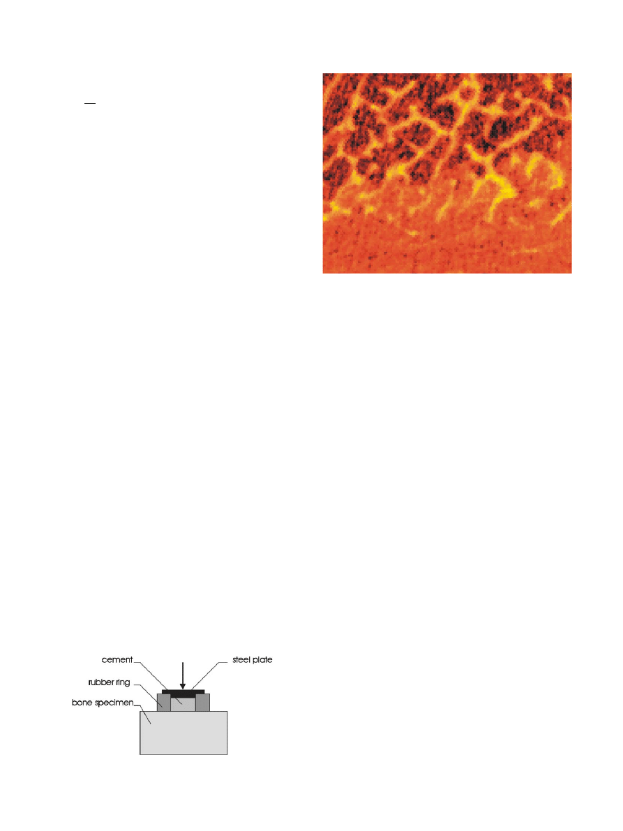
The cement was mixed and placed directly on the
bone surface within a rubber ring.A load of ca.150 N
was applied to the top of the cement while it was curing
(
After curing for 1 h at room temperature, the speci-
men was scanned in a micro-computer tomography
(micro-CT) device (mCT 80, Scanco Medical).A total of
35 sequential images were made at a resolution of
50 50 mm (
.). The thickness of each slice was
50 mm, such that a 3-D reconstruction was obtained that
is built of isotropic voxels.
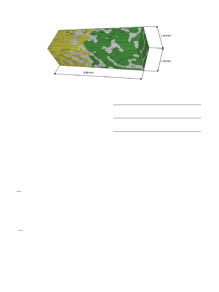
A 1.75 mm 1.75 mm 5.95 mm sub-volume with its
longest edge perpendicular to the bone–cement interface
was selected for further processing (35 35 119 cubic
voxels having edge lengths of 0.05 mm). A modest
Gaussian filtering procedure was used to reduce the
noise in the images after which the domain was
segmented using a two-level threshold procedure.With
this approach, all voxels with a grey-value lower than
the lower-threshold were identified as marrow, those
with a grey-value between the lower and higher thresh-
old were identified as cement, and those with a grey-
value larger than the second threshold value were
identified as bone.This procedure effectively separated
the three materials.However, due to a partial-volume
effect, voxels near the boundary of trabeculae also
displayed grey-values less than the higher threshold.To
avoid that cement properties would be assigned to such
voxels, the 3-D contours of the cement area were
determined and cement properties were assigned only to
voxels within this area.The resulting model could then
be visualised by assigning different colours to the bone,
cement and marrow domains (
2.3. Finite element modelling
A special computer program was written to convert
the 3-D reconstruction generated by the scanning
software to an input file for the finite element code
Abaqus (Abaqus 6.2, Hibbit, Karlsson & Sorensen) that
was used for solving the transient temperature problem
formulated in Eqs.(1)–(6).The final model consisted of
ARTICLE IN PRESS
Fig.1. Experimental setup used to pressurize the bone–cement.
Fig.2.Example of a section through the interface area—micro-CT
image.
M. Sta
!nczyk, B. van Rietbergen / Journal of Biomechanics 37 (2004) 1803–1810
1805
145,775 elements, of which 39,067 (ca.27%) represented
bone tissue, 42,362 (ca.29%) cement and the remain-
ing—bone marrow.
The following initial conditions were applied:
Tj
t¼0
ðxÞ ¼ 300 K;
ð7Þ
wj
t¼0
ðxÞ ¼ 0:01:
ð8Þ
The nonzero initial value for the polymerisation
fraction is necessary for the initialisation of the
polymerisation process (see Eqs.(4) and (5)).For small
values of w|
0
, its exact value does not influence the final
temperature or polymerisation fraction fields.It only
affects the length of the initial ‘‘warm-up’’ period.Based
on results of additional studies that were done to
investigate the role of this parameter, a value w|
0
=1%
was chosen.
On all the walls perpendicular to the interface the
adiabatic condition is adopted:
qT
qn
¼ 0:
ð9Þ
This condition is also applied to the leftmost wall
).It is further assumed that this wall is positioned
at the centre of the cement mantle such that the peak
temperature is reached here.This reasoning gives the
rationale for the adiabatic condition.On the rightmost
wall (
) the convection condition is imposed:
l
qT
qn
¼ h T
0
T
ð
Þ;
ð10Þ
where h=5 (W/m
2
K) (value corresponding to free
convection) and T
0
=310 K.An overview of all thermal
parameters used for the analyses is given in
.The
data were collected from
and
.For marrow, water properties were
assumed.Approximately 52 h of computer time were
required for solving the resulting problem on a SGI
Origin200 workstation computer.
3. Results
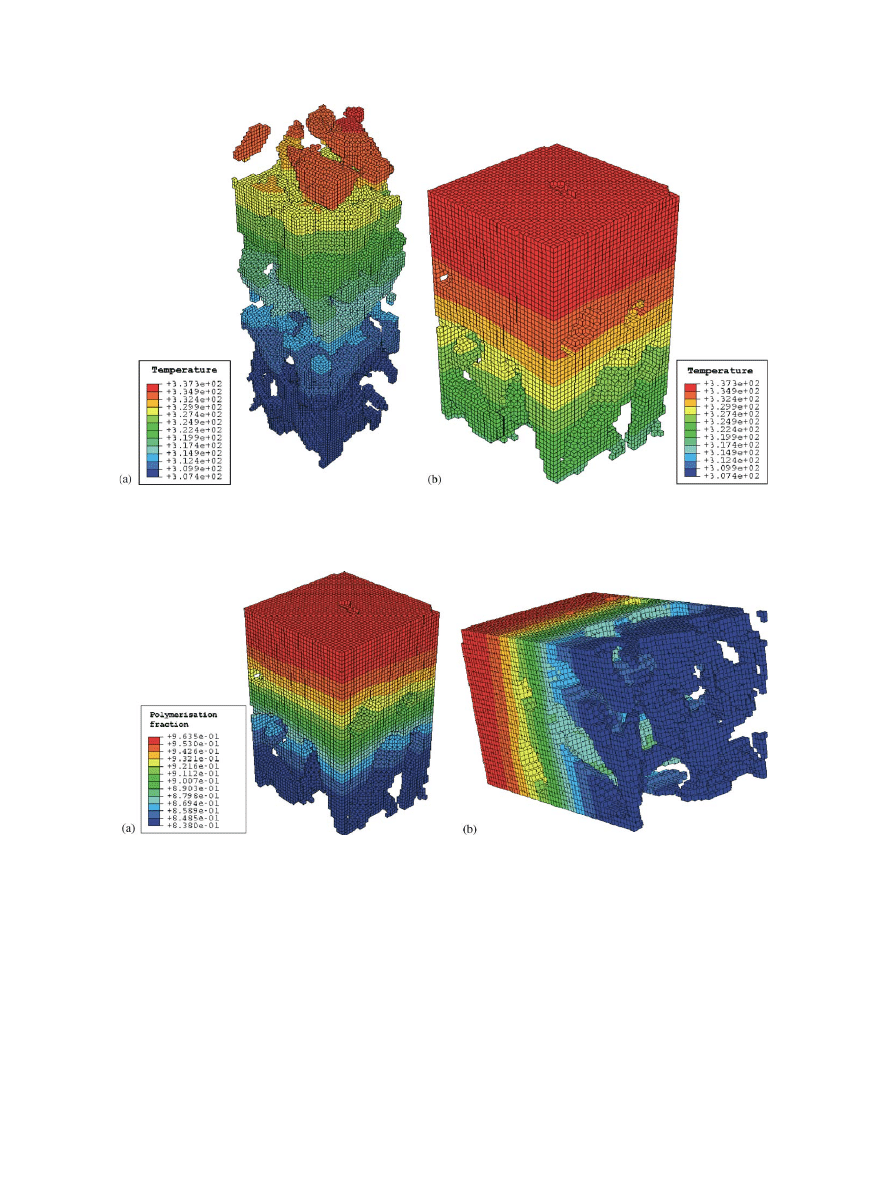
The peak bone temperature was reached at t=112 s
(
.). It can be seen that the temperature in the bone/
marrow region (307 K) is much less than the maximum
values reached in the bone or cement (337 K).
The simulation ended at t=300 s (
) It is clearly
visible that in the region near the bone, the cement
polymerisation fraction (about 84%) is less than that in
the centre (where it is reaching values of over 96%).
After t=300 s the polymerisation is virtually completed;
no further changes in the polymerisation fraction take
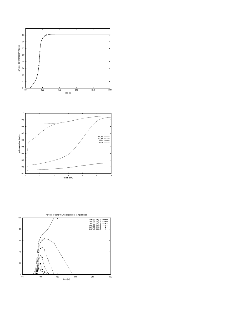
place and the specimen cools down slowly.It can be
clearly seen (
), that the polymerisation fraction
rapidly increases between t=70 and 100 s, at which time
it has reached an average value of about 90%.The
analysis of the polymerisation fraction as a function of
the longitudinal coordinate and time (
) shows that
polymerisation at the centre of the cement occurs earlier
and is more complete than that near the bone interface.
The fraction of bone volume exposed to a tempera-
ture exceeding one of 6 chosen levels: 45
C, 50
C, 55
C,
60
C, 65
C and 70
C seems the most relevant measure
to assess bone cell survival (
).It can be seen, for
example, that all of the bone is exposed to a temperature
higher than 45
C starting from t=140 s until the end of
ARTICLE IN PRESS
Fig.3. The 3-D model of the bone–cement interface.White denotes bone, yellow (light gray) is cement and green (dark gray) is void and marrow.
Table 1
Density
(kg/m
3
)
Thermal
conductivity
(W/mK)
Specific heat
(J/kg/K)
cement
1000
a
0.17
b
1600
b
bone tissue
2000
a
0.4
a
1300
b
marrow
1000
0.6
4190
Data after
a
, water properties were assumed for marrow.
b
.
M. Sta
!nczyk, B. van Rietbergen / Journal of Biomechanics 37 (2004) 1803–1810
1806
the analysis (t=300).Only a small fraction of the bone
(10%), however, is exposed to temperatures exceeding
70
C, and the exposure time to these high temperatures
is limited to 50 s (t=75 until 125).
4. Discussion
According to the presented results, tips of the bone
trabeculae extending deep into cement are exposed, for
short duration, to temperatures in excess of 70
C and
are in a prolonged contact with the volume of
cement containing substantial monomer leftover (more
than 15%, -
).Differences in temperature
throughout the cement mantle are up to 20 K and
differences in the polymerisation fraction reach up to
12.6%. Such inhomogeneities are not described by
temperature-independent
models
of
polymerisation
available in literature (see
;
).To grasp them one
ARTICLE IN PRESS
Fig.4. Temperature distribution when reaching the peak temperature in the bone (at t=112 s).Left: the temperature distribution in bone domain.
Right: the temperature distribution in the cement domain.
Fig.5. Polymerisation fraction distribution in the cement domain at t=300 s.Only the cement domain is shown.The view on the right shows the
cement surface that is in direct contact with the bone.
M. Sta
!nczyk, B. van Rietbergen / Journal of Biomechanics 37 (2004) 1803–1810
1807
needs more elaborate models, such as presented by
(used in the present study),
, Hansen (2003) or
It was found in this study that temperatures in the
bone-marrow region adjacent to the bone–cement
interface were much lower than those in the cement-
embedded trabeculae.Neglecting the bone–cement
interpenetration, as is done in earlier studies that
modelled the bone–cement interface as an infinite thin
layer characterized by its thermal conductivity only,
thus leads to underestimation of the predicted maxi-
mum bone temperature.For example,
calculated a peak bone temperature to be 57
C,
which is clearly much less than the maximum tempera-
ture that we find in this study.Similarly, neglecting the
bone–cement interpenetration will also lead to an
underestimation of peak monomer leftover concentra-
tions.As we demonstrated in this study, this concentra-
tion can be as high as 15% near embedded trabeculae.
Although the average monomer leftover concentration
found in this study (4–5% in the bulk) is in the same
range as values usually reported (
), the
actual local concentration thus can be much higher.
We conclude that modelling the bone microstructure
is essential for the calculation of accurate temperature
and monomer leftover profiles for bone tissues.Pre-
sently, we do not know whether the actual microstruc-
tural geometry has a large effect on the calculated
profiles.It is interesting to note, though, that the generic
2-D micro-model used in the early study of
predicted similar temperatures for the bone
tissue enclosed in the cement (up to 78
C) as is found
in the present study, suggesting that the actual micro-
structure might have only a minor effect on the
results.Unfortunately, this earlier study did not account
for the interface heat capacity nor for the cement
polymerisation kinetics, making it difficult to compare
results presented there with those obtained in our
study.
We also found, that the bone tissue that is subjected
to the highest temperatures is also subjected to high
leftover monomer concentration.Furthermore, the
maximum bone temperature is reached relatively early,
when monomer content in the neighbouring cement is
still quite high.Available experimental data on the effect
of the monomethylmethacrylate monomer on the bone
tissue demonstrate its toxic effects (e.g.
).Thermal necrosis has been reported
in bone tissue exposed to temperatures in excess of 50
C
for more than 1 min (
).It thus seems unlikely that cells subjected
to the conditions found here will survive and necrosis is
expected.Trabeculae embedded in the cement, however,
cannot remodel, and it thus is likely that the bone–
cement interface will remain intact and capable of
ARTICLE IN PRESS
Fig.7.Polymerisation fraction distribution in the cement domain
versus longitudinal coordinate.Depth=0 mm represents the deepest
penetration of cement into the bone, depth=6 mm denotes the center
of the cement mantle.Indicated values represent the average for each
cross-section perpendicular to that axis.
Fig.8. Percentage of tissue exposed to a temperature exceeding each
of the 6 indicated levels.
Fig.6. Average polymerisation fraction versus time.
M. Sta
!nczyk, B. van Rietbergen / Journal of Biomechanics 37 (2004) 1803–1810
1808

load carrying, at least as long as no (micro-) fractures
occur.
The model, developed by
, that
was used in this paper is one of the most advanced
PMMA polymerisation models capable of modelling
the monomer leftover.This is not possible with the
more recent model of
that has been
used in several later studies (
).Very recently,
proposed a
more advanced model that includes the separate
modelling of initiation and chain growth phases of the
polymerisation process.Although such models can
probably further refine and improve the results, we feel
that the model used in this study was adequate for our
purposes.
Some limitations of the present model need to be
discussed.Although the geometry of the bone–cement
interface modelled here was obtained from 3-D mea-
surements, it is not clear if it is representative for the
bone–cement interface found around cemented implants
or after vertebroplasty.The interface will depend on the
bone structure, the preparation of the bone, the
consistency of the cement, the pressure applied to it
when inserted and on the presence of blood, water and
bone debris.In the present experiment the specimen was
cleaned of surface marrow and debris left over from
cutting, dried and cleaned again.Such a thorough
procedure is perhaps not possible in the operating room.
Consequently, the cement penetration found in this
study is expected to be higher that in clinical practice.
report that cement penetration
depth is relatively insensitive to cement pressure, but
washing of the bone surface prior to cement application
increases this depth and increases mechanical strength of
the interface.Therefore maximum cement penetration is
usually regarded as a goal to achieve in orthopaedic
operations.The effects considered in the present paper
may play a vital role then.
Acknowledgements
The present work was done during the first authors
stay in the University of Technology in Eindhoven, the
Netherlands.The first author expresses his thanks to the
scientists working at the Division of Biomedical
Engineering of this University for their hospitality and
to the Centre of Excellence for Advanced Materials and
Structures (AMAS) of the Institute of Fundamental
Technological Research of Polish Academy of Sciences
for financial support of this stay.The first author was
also partially supported by the State Committee for
Scientific Research (KBN, Poland) through the grant
No 4T11F 009 24 and by EC through the project QLK6-
CT-1999-02024.
References
Albrektsson, T., Linder, L., 1984. Bone injury caused by curing
bone cement.Clinical Orthopaedics and Related Research 183,
280–287.
Baliga, B.R., Rose, P.L., Ahmed, A.M., 1992. Thermal modelling of
polymerizing polymethylmethacrylate, considering temperature-
dependent heat generation.Journal of Biomechanical Engineering
114, 251–259.
Borzacchiello, A., Ambrosio, L., Nicolais, L., Harper, E.J., Tanner,
K.E., Bonfield, W., 1998. Comparison between the polymerisation
behavior of a new bone cement and a commercial one: modelling
and in vitro analysis.Journal of Materials Science: Materials in
Medicine and Biology 9, 835–838.
Deramond, H., Wright, N.T., Belkoff, S.M., 1999. Temperature
elevation caused by bone cement polymerisation during vertebro-
plasty.Bone 25, 17S–21S.
DiPisa, J.A., Sih, G.S., Berman, A., 1976. The temperature problem at
the bone-acrylic cement interface of the total hip replacement.
Clinical Orthopaedics 121, 95–98.
Dunne, N.J., Orr, J.F., 2002. Curing characteristics of acrylic bone
cement.Journal of Materials Science: Materials in Medicine and
Biology 13, 17–22.
Eriksson, R.A., Albrektsson, T., Magnusson, B., 1984. Assesment of
bone viability after heat trauma.A histological histochemical and
vital microscopic study in rabbit.Scandinavian Journal of Plastic
and Reconstructive Surgery 18, 261–268.
Feith, R., 1975. Side-effects of acrylic cement implanted into bone.
Acta Orthopaedica Scandinavica (Suppl) 161, 1–136.
Fukushima, H., Hashimoto, Y., Yoshiya, S., Kurosaka, M., Matsuda,
M., Kawamura, S., Iwatsubo, T., 2002. Conduction analysis of
cement interface temperature in total knee arthroplasty.Kobe
Journal of Medical Sciences 48, 63–72.
Hansen, E., 2003. Modelling heat transfer in a bone–cement–prosthesis
system.Journal of Biomechanics 36, 787–795.
Homsy, C.A., Tullos, H.S., Anderson M, .S., 1972. Some physiological
aspects of prosthesis stabilisation with acrylic polymer.Clinical
Orthopaedics 83, 317–328.
Huiskes, R., 1980. Some fundamental aspects of human joint
replacement.Acta Orthopaedica Scandinavica 185.
Ishihara, S., Goshima, T., Kanekasu, K., McEvily, A.J., 2002.
The static and cyclic strength of a bone–cement bond.Journal
of Materials Science: Materials in Medicine and Biology 13,
449–455.
Jefferis, C.D., Lee, A.J., Ling R, .S., 1975. Thermal aspects of self-
curing polymethylmethacrylate.Journal of Bone and Joint Surgery
(British Ed.) 57, 511–518.
K
.uhn, K.D., 2002. Bone Cements: Up-to-date Comparison of Physical
and Chemical Properties of Commercial Materials.Springer,
Berlin.
Lennon, A.B., Prendergast, P.J., 2002. Residual stress due to curing
can initiate damage in porous bone cement: experimental and
theoretical evidence.Journal of Biomechanics 35, 311–321.
Linder, L., 1977. Reaction of bone to the acute chemical trauma of
bone cement.Journal of Bone and Joint Surgery 59-A, 82–87.
Lu, J.X., Huang, Z.W., Tropiano, P., Clouet d’Orval, B., Remusat,
M., Dejou, J., Proust, J.-P., Poitout, D., 2002. Human biological
reactions at the interface between bone tissue and polymethyl-
methacrylate cement.Journal of Materials Science: Materials in
Medicine and Biology 13, 803–809.
Mazzullo, S., Paolini, M., Verdi, C., 1991. Numerical simulation of
thermal bone necrosis during cementation of femoral prosthesis.
Journal of Mathematical Biology 29, 475–494.
Rouiller, C., Majno, G., 1953. Morphologische und chemische untersu-
chung an knochen nach hitzeeinwirkung.Beitrage zur Pathologischen
Anatomie und zur Allgemeinen Pathologie 113, 100–120.
ARTICLE IN PRESS
M. Sta
!nczyk, B. van Rietbergen / Journal of Biomechanics 37 (2004) 1803–1810
1809

Sta
!nczyk, M., Study on modelling of PMMA bone cement
polymerisation.Journal of Biomechanics, submitted.
Starke, G.R., Birnie, C., van den Blink, P.A., 1998. Numerical
modelling of cement polymerisation and thermal bone necrosis.in:
Middleton, J., Jones, M. L., Pande G. N. (Eds.), Computer
Methods in Biomechanics and Biomedical Engineering—2.Gor-
don and Breach Sciences Publishers pp.163–172.
Swenson Jr., L.W., Schurman, D.J., Piziali, R., 1981. Finite element
temperature analysis of a total hip replacement and measurement
of pmma curing temperatures.Journal of Biomedical Materials
Research 15, 83–96.
Toksvig-Larsen, S., Franzen, H., Ryd, L., 1991. Cement interface
temperature in hip arthoplasty.Acta Orthopaedica Scandinavica
62, 102–105.
Willert, H.G., Ludwig, J., Semlitsch, M., 1974. Reaction of bone to
methacrylate after hip arthoplasty.Journal of Bone and Joint
Surgery 56-A, 1368–1382.
ARTICLE IN PRESS
M. Sta
!nczyk, B. van Rietbergen / Journal of Biomechanics 37 (2004) 1803–1810
1810
Document Outline
Wyszukiwarka
Podobne podstrony:
Ansys Thermal Analysis Guide id Nieznany (2)
4 Coupled Structural Thermal Analysis
Comparative study based on exergy analysis of solar air heater collector using thermal energy storag
Parametric Analysis of the Simplest Model of the Theory of Thermal Explosion the Zel dovich Semenov
GbpUsd analysis for July 06 Part 1
Decline of Contrastive Analysis Pedagogy
An%20Analysis%20of%20the%20Data%20Obtained%20from%20Ventilat
Microwaves in organic synthesis Thermal and non thermal microwave
kurs excel (ebook) statistical analysis with excel X645FGGBVGDMICSVWEIYZHTBW6XRORTATG3KHTA
Lab 2 Visual Analyser oraz kompresje v2
A Contrastive Analysis of Engli Nieznany (3)
05 PRELIMINARY ANALYSES answers
Analysis of soil fertility and its anomalies using an objective model
53 755 765 Effect of Microstructural Homogenity on Mechanical and Thermal Fatique
Pancharatnam A Study on the Computer Aided Acoustic Analysis of an Auditorium (CATT)
więcej podobnych podstron