62
03-2011 elektor
ATM18
A String of 160
R
G
B
LEDs
A colourful display
By Grégory Ester (France)
Colours are not just mood indicators, apparently they can also lift or dampen your general mindset to
a degree. If you want to attract attention during some event, decorate a shop window, or add a bit of
ambience to a party, you can do all this and more with this high-tech light string — and what’s more, it’s
self-adhesive.
Pale LEDs that just flash, or don’t, are out — make way for a new generation of lighting effects!
This project will let you control a string of RGB LEDs using either a
touch screen or a colour detector. In the first case, you can use your
finger or a stylus; the second will require pieces of red, green, and
blue card… Sounds interesting? Then to your boards (ATM18), you
have the green light to start wiring!
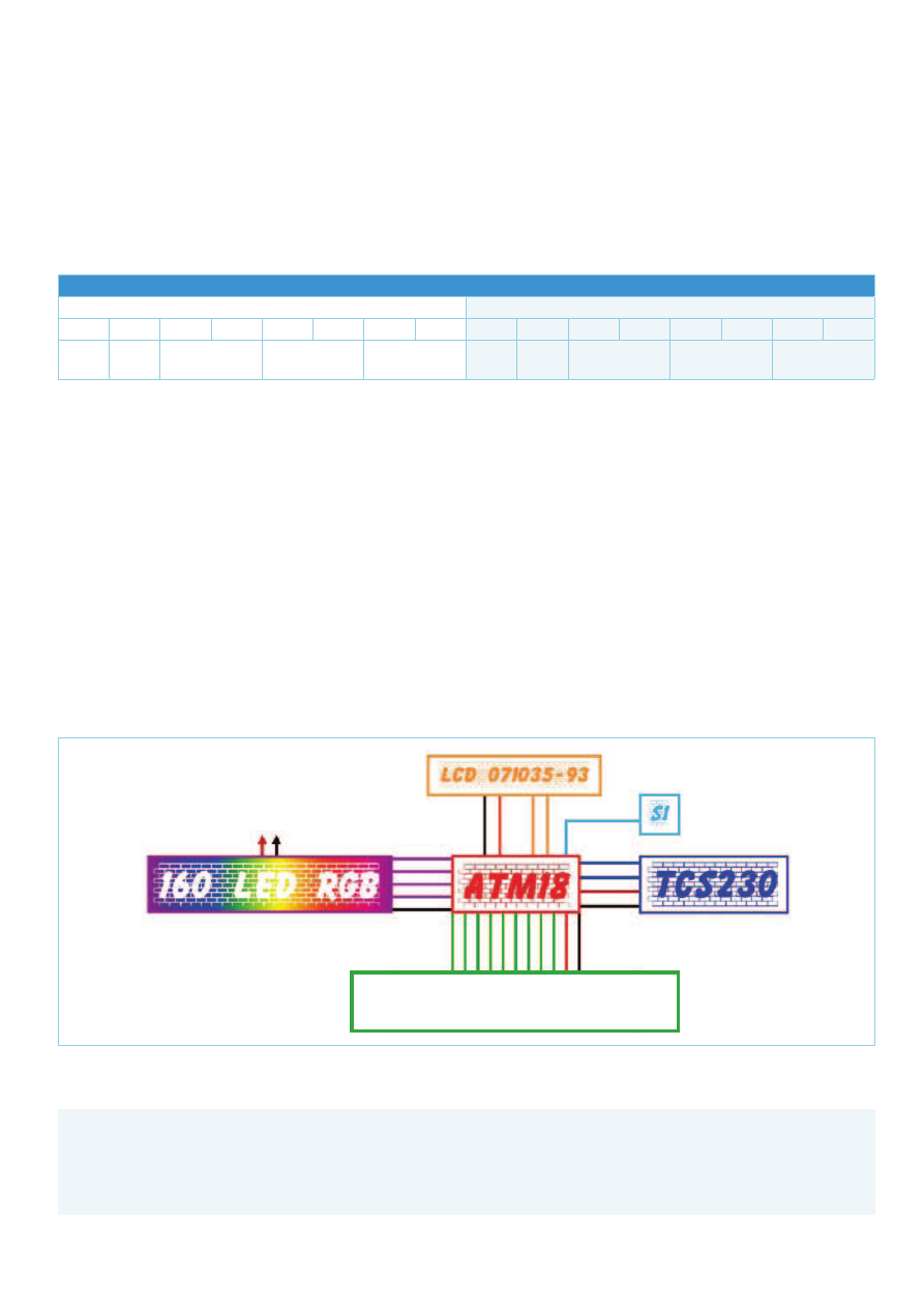
Block diagram for a colourful connection
This project uses the Elektor ATM18 board
[1]
, a colour detector
[2]
,
a 128 × 64 pixel graphical LCD touchscreen
[3]
, the Elektor 2-wire
display
[4]
and a string of RGB LEDs
[5]
. Provision has been made for
two configurations for controlling the string: via the touch screen
(without the colour detector or the 2-wire display) or via the colour
detector and using the 2-wire display (without the touch screen).
Figure 1 shows how to connect up all the modules so as to test both
operating modes. So you can load one or other of the two bits of
firmware 74_DOGM_HL1606.hex or 75_HL1606_TCS230.hex with-
out having to modify the wiring. Table 1 shows you which peripher-
als are active, depending on the program loaded. The firmware and
source code files are available free from
[3]
.
But how can we control these lights?
The string
[6]
is manufactured by Astro-Fly Lighting Technology
in Hong-Kong and is readily available on the Internet (
[5]
, eBay, or
search for “HL1606 5050”). It comprises a number of 6.2 cm (2.45
inch) long segments. Each segment includes two RGB LEDs that can
be driven independently via an SPI synchronous serial link. The seg-
ments also have a self-adhesive strip, so it’s easy to stick the string
onto any surface.
To be able to control the string in your own fashion and create your
own effects, it’s necessary to take a closer look at how the whole
thing works. So let’s light up just the first two blue LEDs and look at
the resulting signals on the oscilloscope. But just before we do, let’s
see how to put together the burst of bits to be transmitted over the
serial link in synchronization with the clock signal.
Table 1. Two operating modes.
Configuration
Peripherals used
Colour detector (75_HL1606_TCS230.hex)
TCS230
ATM18
2-wireLCD
RGB string
Graphical LCD touch screen (74_DOGM_HL1606.hex)
LCD Touch screen
ATM18
RGB string
63969
63
elektor 03-2011
ATM18
Each RGB LED is driven by eight bits. Each of its three colour
cells (red, green, or blue) is controlled by two bits, allowing four
combinations:
00: LED out
01: LED lit, brightness always at maximum
10: the brightness increases gradually from minimum to maxi-
mum, faster or slower, depending on the signal S_I
11: the brightness reduces gradually from maximum to mini-
mum, faster or slower, depending on the signal S_I
The ‘fade speed’ function makes it possible set the speed at which
the brightness of each LED fades up or down. One bit is set aside
for this:
0: slow fade up/down
1: fast fade up/down
Adding a validation bit (Latch), to let us confirm the whole thing or
not, completes our 8-bit byte. If this bit is zero, all the commands
are ignored — this is a way of inserting transparent configurations
that have no effect on the LED.
Hence it takes two bytes to control the segment’s two RGB LEDs.
Table 2 sums up the arrangement of the bits in the two bytes. The
MSB (D16) will be transmitted first over the serial link. Once the
pair of bytes has been transmitted, the transmission has to be con-
firmed. Pin L_I receives the confirmation pulse.
A small extract of a few lines from the program written in BASCOM-
AVR will illustrate how we make the two blue LEDs in the first seg-
ment light at full brightness.
Color_array(4) = &B10010000 ‘BLUE
For X = 1 To 2
Elektor Products & Services
PCB: Elektor # 100743-1
PCB design (free download): # 100743-1.pdf
Firmware & source code (free download): # 100743-11.zip
ATM18 controller board: Elektor # 071035-91
ATM18 piggy-back board: Elektor # 071035-92
2-wire display: Elektor # 071035-93
Hyperlinks in article
All items accessible through www.elektor.com/100743
PD3
100743 - 13
PC4
PC5
PD6
S
_
I
5V/3A
D
_
I
CK
_
I
L
_
I
GND
PD5
PB5
PB3
PD7
PD4
PC3
PC2
PC1
PC0
RST
SCL
SI
A0
CS1
R
T
L
B
5V
GND
5V
GND
PB1
PB2
PB0
CLK
DA
TA
ATM18-K8
(1)
PD1
PD0
RXD
TXD
5V
GND
touchscreen_LCD
Figure 1. Block diagram of the LED string controller.
Table 2. Summary of the 16 bits for configuring one segment of the string.
First RGB LED
Second RGB LED
D16
D15
D14
D13
D12
D11
D10
D9
D8
D7
D6
D5
D4
D3
D2
D1
latch
fade
speed
blue
red
green
latch
fade
speed
blue
red
green
63969
64
03-2011 elektor
ATM18
Spiout Color_array(4) , 1
Next X
Set L
Waitus 3
Reset L
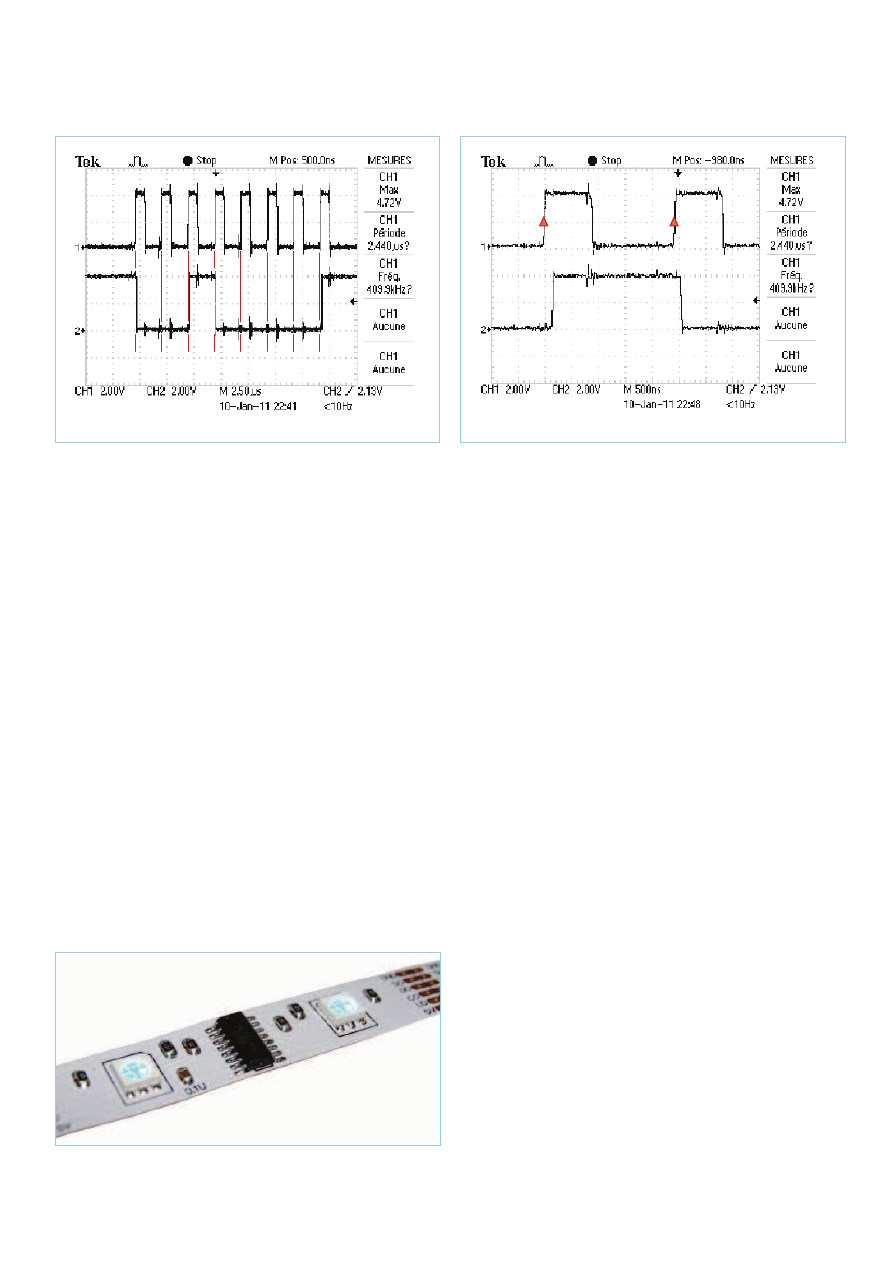
Figure 2 shows a graphical display of the first byte; the data
is regarded as valid during the rising edge of the clock signal
(Figure 3).
In Figure 4, the LEDs are shining brightly… OK, I admit you can’t
really see that in this photo, but I can promise you that in reality,
they’re shining out in topaz blue! By using the method described in
the article “LEDs and Illumination – How much light does that LED
give?”
[7]
, I obtain an f-stop/exposure time combination of f5,6/(2
to 4) with sensitivity set at 100 ISO; this corresponds to a lighting
level of around 20 to 40 lux in my little workshop.
A transition to create an effect
Now we’re going to send 160 bytes that will enable us to obtain a
dissolve from green to red on all 160 LEDs simultaneously. The tran-
sition will last 1.4 s — with the precision due to Timer0.
Now, going from green through orange to red is all very pretty —
but how does it work? The answer lies in the program extract below,
which is analysed below.
Config Timer0 = Timer , Prescale = 1024
On Ovf0 Timer0_isr
…
Color_array(28) = &B10001011
…
Fade_speed = 170
Launch_fade
For x = 1 To 160
Spiout Color_array(28) , 1
Next x
Latch
Wait 5
…
Timer0_isr:
Timer0 = Fade_speed
Toggle S_i
Return
…
Sub Launch_fade
Enable Timer0
End Sub
16 MHz / 1024 = 15,625 Hz; Timer0 is enabled at a rate of
15,625 Hz.
(1/15625) × 2
8
= 16.384 ms; this is an 8-bit counter, so it over-
flows every 16.384 ms. This is the rate at which the interrupt
routine should be executed. Only ‘should’, since in fact Timer0
is preset to 170 by the variable ‘Fade_speed’.
(1/15625) × (256−170) = 5.5 ms; so S_I is going to change
state every 5.5 ms (Toggle S_i), thereby generating the pulses
needed to advance the colour dissolve. So one pulse is gener-
ated every 11 ms.
Color_array(28) = &B10001011; the brightness of the red is
set at minimum (D12 = D4 = 1, D11 = D3 = 0) while the green
(D10 = D2 = 1, D9 = D1 = 1) starts out at maximum. Each pulse
will gradually increase the red light and similarly reduce the
green. After 128 pulses, the string will be completely red.
128 × 11 ms = 1.4 s; so the dissolve will have lasted 1.4 s. If bits
D15 and D7 had been set to 1, the transition would have lasted
1.4/2 = 0.7 s.
1
2
3
4
5
6
7
8
1
0
0
1
0
0
0
0
100743 - 14
100743 - 15
3
4
0
1
Figure 2. One byte transmitted in sync with the clock.
Figure 3. Zoomed detail of the synchronisation.
Figure 4. Just one of the 80 segments!
63969
65
elektor 03-2011
ATM18
The effects are countless and magnificent, believe me! So we can
select some of them, we’re going to use two solutions — two differ-
ent man/machine interfaces.
Beware of the dog
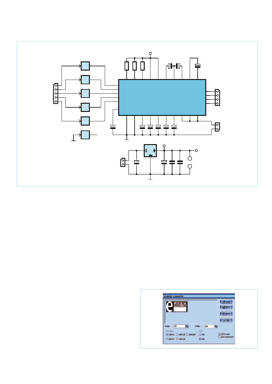
The DOGM128W-6 128 × 64 pixel graphic LCD using the FSTN tech-
nique is manufactured by Electronic Assembly
[8]
. In this application,
we’re using it sandwiched between the LED backlight module (sev-
eral colours are available) and the touch panel. This sandwich is not
a ready-made module, but an Elektor PCB. The extremely simple
circuit diagram is shown in Figure 5. The board is available from
[3]
(Elektor # 100743-1).
This display offers excellent contrast and very interesting software
implementation, as BASCOM-AVR has a library for controlling it.
Config Graphlcd = 128 * 64eadogm, Cs1 =
Portd.4, A0 = Portd.7, Si = Portb.3, Sclk =
Portb.5, Rst = Portd.5
To create your graphical interface, nothing could be simpler. All you
have to do is design it in BMP format and then use BASCOM-AVR’s
built-in graphic converter (Figure 6) to create the file with the same
name, but with an extension recognized by the compiler — here
‘background_1.bgf’.
Showpic 1 , 1 , Picture1
Lcdat 6 , 50 , “WELCOME!”
Wait 1
Lcdat 6 , 50 , “ “
Lcdat 6 , 50 , “PROGRAM:”
…
Picture1:
$bgf “background_1.bgf”
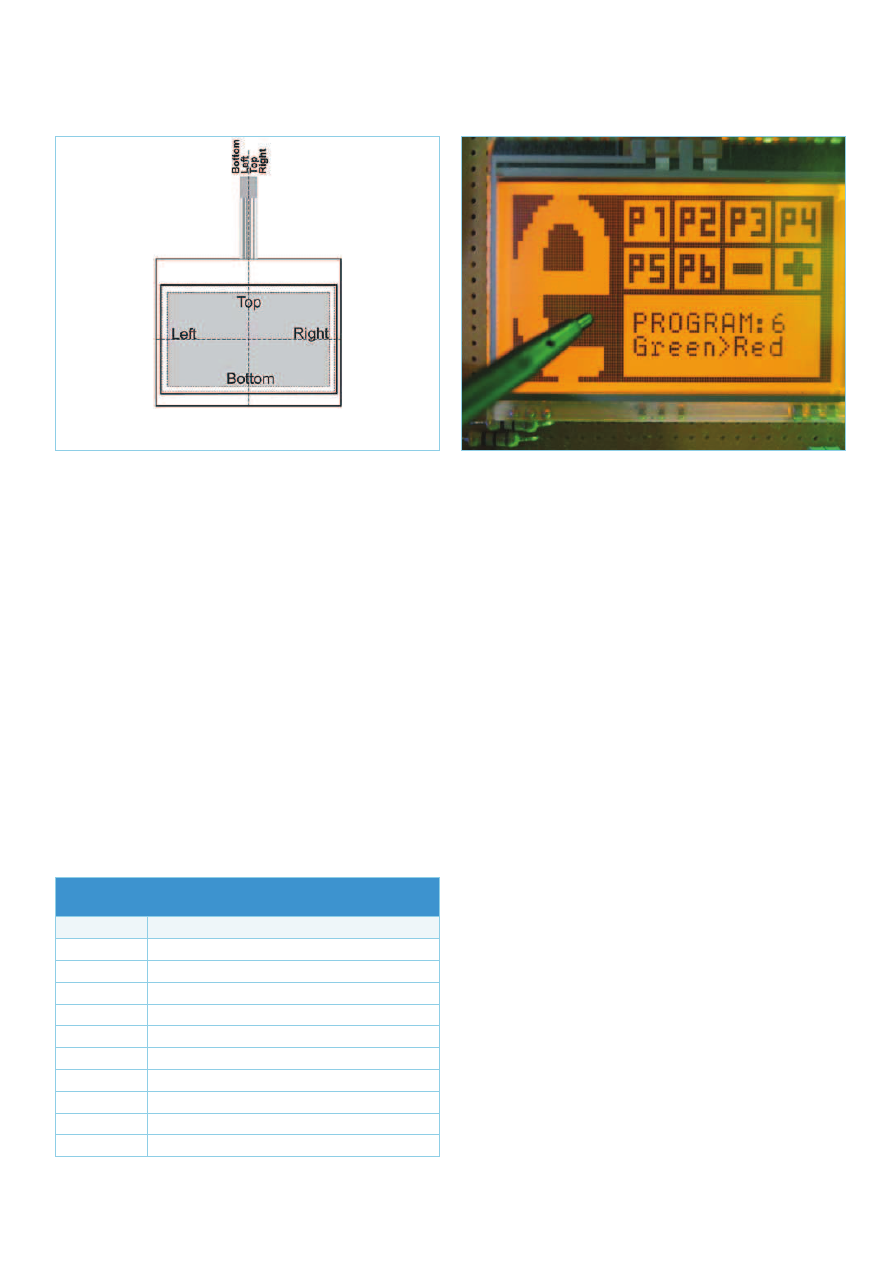
The touch pad (Figure 7) can be likened to two potentiometers
whose values are read as follows:
Apply a voltage of 5 V between the ‘TOP’ and ‘BOTTOM’ pins,
and between ‘LEFT’ and ‘RIGHT’ you will read a voltage propor-
tional to the horizontal displacement of your stylus (Y position).
Next apply a voltage between ‘LEFT’ and ‘RIGHT’, and this time
reading between the ‘TOP’ and ‘BOTTOM’ pins gives us the X
3
2
1
IC2A
5
4
1
IC2B
7
6
1
IC2C
10
9
1
IC2D
12
11
1
IC2E
15
14
1
IC2F
RST
SCL
SI
A0
CS1
CS1_5V
A0_5V
SI_5V
SCL_5V
RST_5V
C12
1u
C11
1u
C10
1u
C9
1u
C8
1u
C4
1u
C6
1u
C7
1u
C13
1u
K4
R1
4
7
R
R2
4
7
R
R3
4
7
R
3V3
K3
TP
BL
K2
IC1
MCP1702
C1
10u
C2
10u
V
CC
3V3
C5
100n
C3
100n
K1
A
1
+
1
A
2
+
2
A
3
+
3
C1-
1
8
C2-
1
9
C3-
2
0
V
0
2
1
V
1
2
2
V
2
2
3
V
3
2
4
V
4
2
5
V
S
S
2
6
C
A
P
2
N
2
7
C
A
P
2
P
2
8
C
A
P
1
P
2
9
C
A
P
1
N
3
0
C
A
P
3
P
3
1
VOUT
32
V
S
S
3
3
V
D
D
2
3
4
V
D
D
3
5
SI
36
SCL
37
A0
38
RST
39
CS1B
40
BOTTOM
41
LEFT
42
TOP
43
RIGHT
44
LCD1
DOGM128
1
8
IC2
IC2 = MHC4050B1R74
100743 - 11
128 x 64
Figure 6. ‘Graphic Converter’ under BASCOM-AVR.
Figure 5. Circuit of the graphical touch screen.
63969
66
03-2011 elektor
ATM18
position proportional to the displacement of the stylus from top
to bottom.
Hence X and Y will be the co-ordinates of the point where the stylus
contacts the touch pad. Nothing could be simpler to handle, using
our microcontroller’s built-in ADC.
In this way, our program recognizes nine zones (Figure 8). Six of these
correspond to six programmes from P1 to P6 that are directly acces-
sible. Pressing with your finger or a stylus in the relevant zone displays
the name of the programme. You can also move around from 1 to 10
using the + or − ‘buttons’. Programme 7, for example, can only be
accessed this way. Confirm by pressing the ‘e’ for ‘Elektor’.
A digital retina
The TCS230 module
[2]
incorporates the TAOS optical sensor of the
same name, which lets us measure colours with wavelengths from
350–750 nm for light levels of at least 100 lux. We have three pos-
sibilities for recovering digital or analogue information that repre-
sents the colours present in front of the 6 mm diameter lens:
A variable linear voltage that reflects the red, green, or blue
values;
An SPI link for reading digital information in the form of bytes;
An asynchronous serial link and a syntax in the form of ASCII
characters. In this instance, we’ve opted to communicate using
the UART that is physically present in our ATmega88.
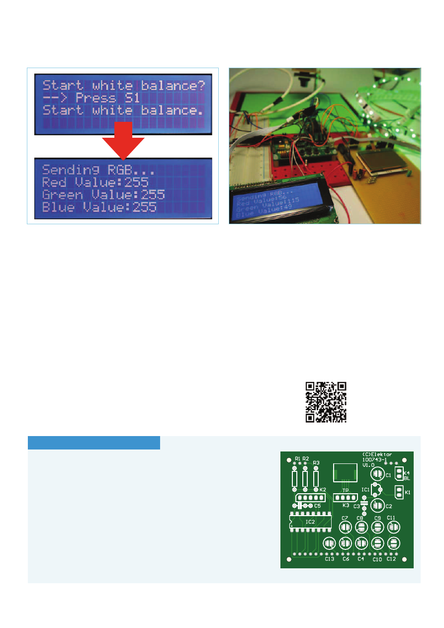
After loading the firmware ‘75_HL1606_TCS230.hex’, you can cali-
brate the sensor by pressing S1 at start-up or after a reset, with the
sensor’s lens aimed at a white object:
If S1 = 0 Then Print “$sure wb” ; Chr(_cr) ;
Chr(_lf) ; ‘Start White Balance
The surface viewed at this moment will henceforth become the sole
reference so that the module will then be able to break down col-
ours viewed into the three colours red, green, and blue.
The 2-wire display
Once the white balance has been performed (Figure 9), the 2-wire
display (
[4]
, Elektor # 071035-93) displays, in rotation, three bytes
in decimal (0–255) representing the colours measured. Here are the
five operating modes the program offers, depending on the colour
seen by the lens:
– Red card: the string lights up red
– Green card: the string lights up green
– Blue card: the string lights up blue
– White: the string lights up with all lights blazing
– Black (the cap is fitted over the lens): lights out!
An example for green (Figure 10): unless your card is a perfect
green, in which case there will be no ambiguity in detecting it, it will
be necessary to adjust the limits so as to filter out the other colours:
If Var_green > 150 And Var_blue < 140 And Var_
Figure 7. The touch panel.
Figure 8. EALED55x46A + EADOGM128W-6 + EATOUCH128-1.
Table 3. The effects available. Programmes 8–10 are free, the
effects they produce will depend on your own imagination.
Programme
Description
1 (P1)
Red snake followed by a blue snake
2 (P2)
« Crazy snake »
3 (P3)
Red or green? Green or red?
4 (P4)
Succession of colours
5 (P5)
A symphony of colours!
6 (P6)
Green to red via orange — are you following?
7 (P7)
Progressively towards blue
8 (P8)
Free
9 (P9)
Free
10 (P10)
Free
63969
67
elektor 03-2011
ATM18
red < 140 Then
For X = 1 To 160
Spiout Color_array(2) , 1
Next X
Latch
Wait 1
End If
If in the rarest of cases the string itself fails to draw attention, this
novel way of controlling it will, albeit from an different audience.
(100743)
Internet Links
[1] www.elektor.com/atm18
[2] www.sureelectronics.net/goods.php?id=959
[3] www.elektor.com/100743
[4] www.elektor.com/071035
[5] www.ledlight-lamp.com/cp/html/?310.html or
www.lextronic.fr/P19361-flexible-a-leds-RVB.html
[6] www.ledlight-lamp.com/cp/html/?310.html
[7] www.elektor.com/100621
[8] www.lcd-module.com/products/dog.html
Figure 10. Rather green!
Figure 9. White balance.
COMPONENT LIST
Resistors
R1, R2, R3 = 47 Ω
Capacitors
C1,C2 = 10µF 25V radial, lead pitch 2.5mm
C3,C5 = 100nF, lead pitch 5mm or 7.5mm
C4,C6–C13 = 1µF 16V radial, lead pitch 2.5mm
Semiconductors
IC1 = MCP1702-3302E/TO (TO-92)
IC2 = 74HC4050N (DIP-16)
Miscellaneous
LCD1 = LCD, graphic, Electronic Assembly type
EA DOGM128X-6
Touchscreen, Electronic Assembly type EA
TOUCH128-1
K5 = ZIF connector for touchscreen, Elec-
tronic Assembly type EA WF100-04S
Backlight module = Electronic Assembly
type EA LED55x31-W (W=white, other
colours availabe, see LCD1 datasheet
[8])
K1 = 2-way pinheader socket, lead pitch
0.1 in. (2.54mm)
K2 = 5-way pinheader socket, lead pitch
0.1 in. (2.54mm)
K3 = 4-way pinheader socket, lead pitch
0.1 in. (2.54mm)
K4 = wire link or 2-pin pinheader with
jumper, lead pitch 0.1 in. (2.54mm)
Jumper or switch for K4.
PCB # 100743-1, see [3]
63969
Wyszukiwarka
Podobne podstrony:
Constant current driving of the RGB LED
String of Leaves
How to Use RGB LEDs Backlight o Nieznany
Constant current driving of the RGB LED
Anderson, Kevin J Music Played on the Strings of Time
A String Of Pearls
adafruit arduino lesson 3 rgb leds
A String of pearls 2
pair production of black holes on cosmic strings
Constant current driving of the LEDs group
Application of LEDs in road lighting
32856182 Best of Stringing TOC
Constant current driving of the LEDs group
Measurements of the temperature dependent changes of the photometrical and electrical parameters of
Physical Interpretation of the 26 Dimensions of Bosonic String Theory
An Empirical Comparison of C C Java Perl Python Rexx and Tcl for a Search String Processing Pro
Physics Papers Edward Witten (2000), The Cosmological Constant From The Viewpoint Of String Theory
więcej podobnych podstron