Arduino Lesson 3. RGB LEDs
Created by Simon Monk
Last updated on 2013-06-22 06:45:59 PM EDT

2
3
4
4
4
6
8
9
12
13
14
Guide Contents
Breadboard Layout
Colors
Arduino Sketch
Using Internet Colors
Theory (PWM)
Other Things to Do
© Adafruit Industries
http://learn.adafruit.com/adafruit-arduino-lesson-3-rgb-leds
Page 2 of 14
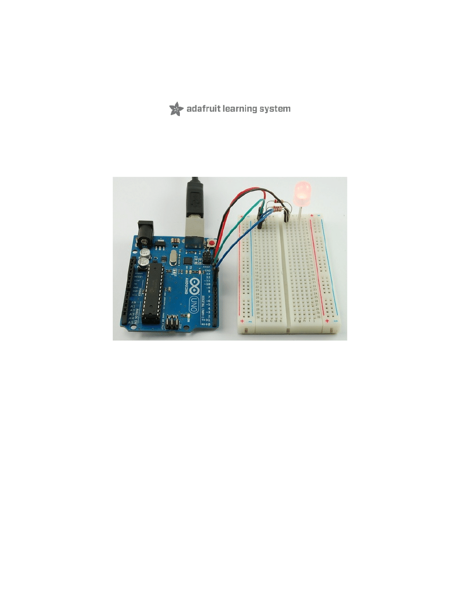
Overview
In this lesson, you will learn how to use a RGB (Red Green Blue) LED with an Arduino.
You will use the analogWrite function of Arduino to control the color of the LED.
At first glance, RGB (Red, Green, Blue) LEDs look just like regular LEDs, however, inside the
usual LED package, there are actually three LEDs, one red, one green and yes, one blue. By
controlling the brightness of each of the individual LEDs you can mix pretty much any color you
want.
We mix colors just like you would mix audio with a 'mixing board' or paint on a palette - by
adjusting the brightness of each of the three LEDs. The hard way to do this would be to use
different value resistors (or variable resistors) as we played with in lesson 2. That's a lot of
work! Fortunately for us, the Arduino has an analogWrite function that you can use with pins
marked with a ~ to output a variable amount of power to the appropriate LEDs.
© Adafruit Industries
http://learn.adafruit.com/adafruit-arduino-lesson-3-rgb-leds
Page 3 of 14
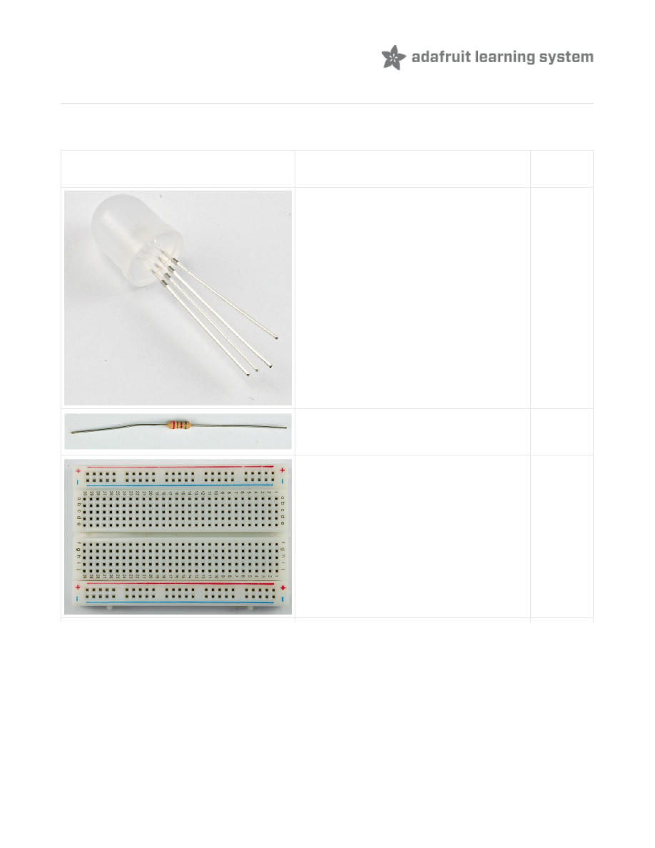
Parts
To build the project described in this lesson, you will need the following parts.
Part
Qty
Diffuse RGB LED 10mm
1
270 Ω Resistors (red, purple, brown
stripes) - you can use up to 1K ohm
although it will be a little dimmer
3
Half-size Breadboard
1
© Adafruit Industries
http://learn.adafruit.com/adafruit-arduino-lesson-3-rgb-leds
Page 4 of 14
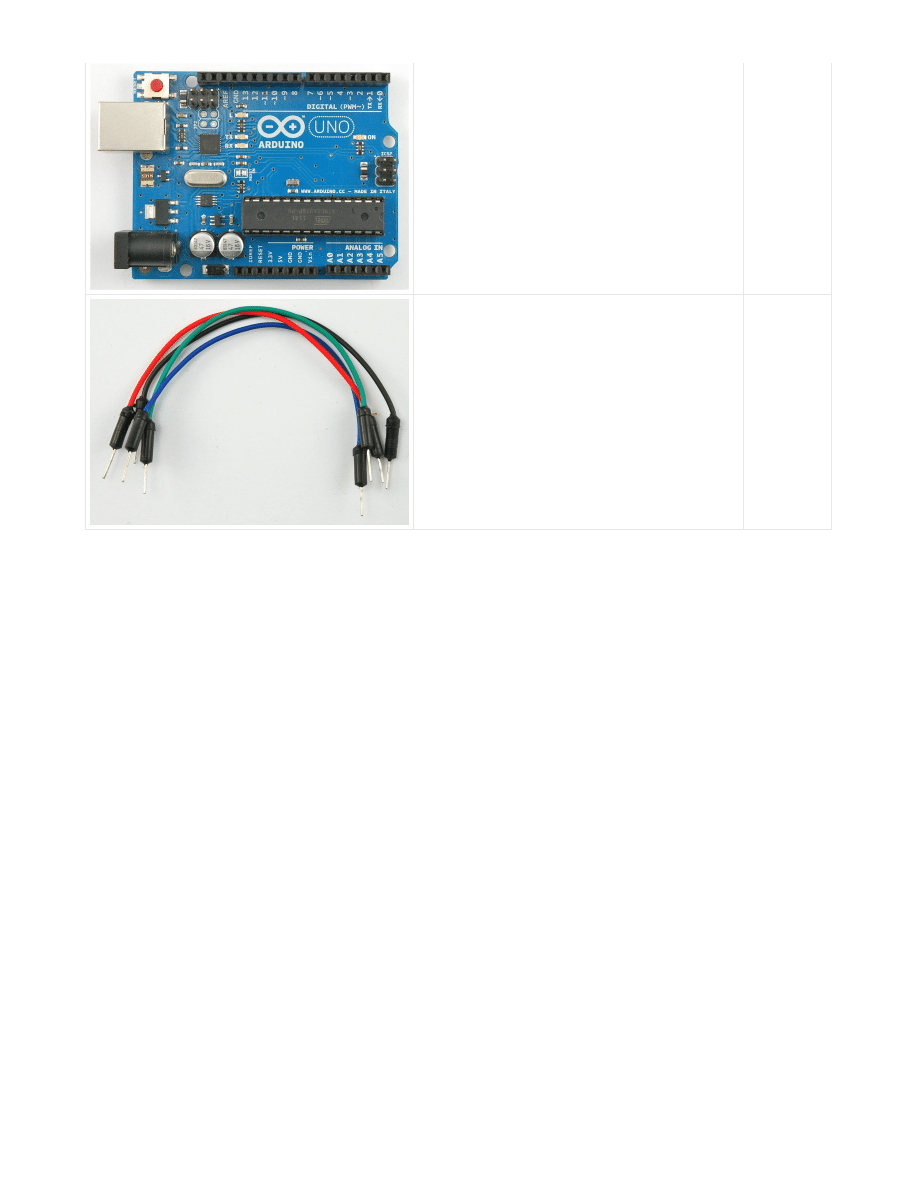
Arduino Uno R3
1
Jumper wire pack
1
© Adafruit Industries
http://learn.adafruit.com/adafruit-arduino-lesson-3-rgb-leds
Page 5 of 14

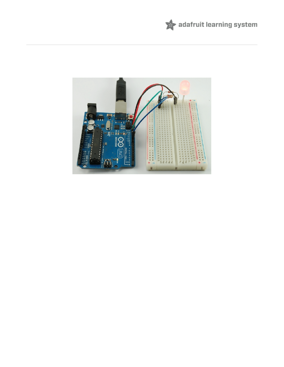
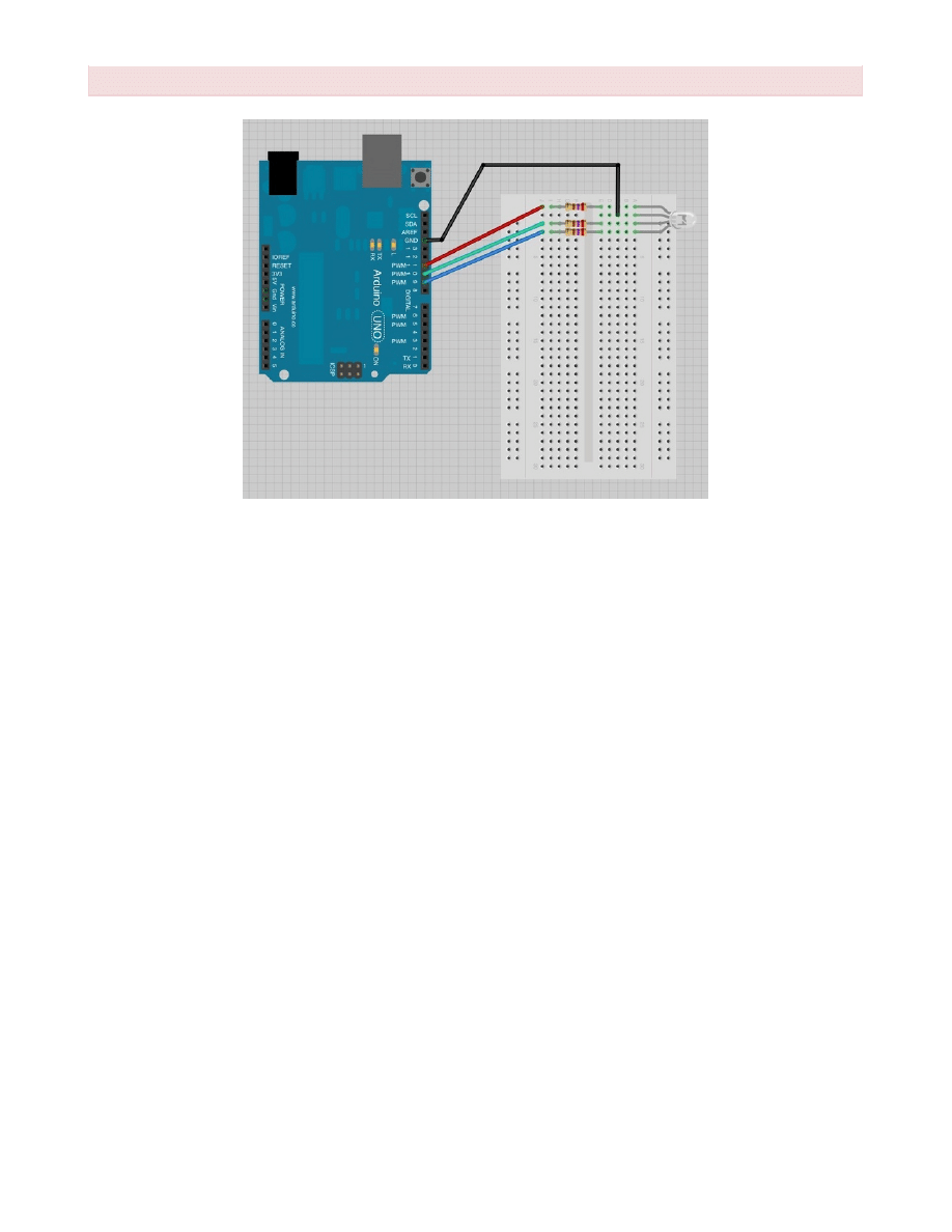
Breadboard Layout
The RGB LED has four leads. There is one lead going to the positive connection of each of the
single LEDs within the package and a single lead that is connected to all three negative sides of
the LEDs.
The common negative connection of the LED package is the second pin from the flat side of
the LED package. It is also the longest of the four leads. This lead will be connected to ground.
Each LED inside the package requires its own 270Ω resistor to prevent too much current
flowing through it. The three positive leads of the LEDs (one red, one green and one blue) are
connected to Arduino output pins using these resistors.
If you are using a common ANODE LED instead of common CATHODE, connect the
If you are using a common ANODE LED instead of common CATHODE, connect the
© Adafruit Industries
http://learn.adafruit.com/adafruit-arduino-lesson-3-rgb-leds
Page 6 of 14
If you are using a common ANODE LED instead of common CATHODE, connect the
If you are using a common ANODE LED instead of common CATHODE, connect the
long pin to +5 instead of ground
long pin to +5 instead of ground
© Adafruit Industries
http://learn.adafruit.com/adafruit-arduino-lesson-3-rgb-leds
Page 7 of 14
Colors
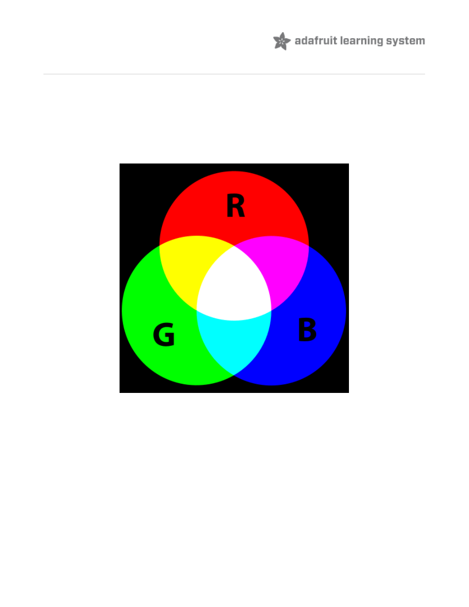
The reason that you can mix any color you like by varying the quantities of red, green and blue
light is that your eye has three types of light receptor in it (red, green and blue). Your eye and
brain process the amounts of red, green and blue and convert it into a color of the spectrum.
In a way, by using the three LEDs we are playing a trick on the eye. This same idea is used in
TVs, where the LCD has red, green and blue color dots next to each other making up each
pixel.
If we set the brightness of all three LEDs to be the same, then the overall color of the light will
be white. If we turn off the blue LED, so that just the red and green LEDs are the same
brightness, then the light will appear yellow.
We can control the brightness of each of the red, green and blue parts of the LED separately,
making it possible to mix any color we like.
Black is not so much a color as an absense of light. So the closest we can come to black with
our LED is to turn off all three colors.
© Adafruit Industries
http://learn.adafruit.com/adafruit-arduino-lesson-3-rgb-leds
Page 8 of 14
Arduino Sketch
The following test sketch will cycle through the colors red, green, blue, yellow, purple, and
aqua. These colors being some of the standard Internet colors.
Try the sketch out and then we will dissect it in some detail......
The sketch starts by specifying which pins are going to be used for each of the colors:
/*
Adafruit Arduino - Lesson 3. RGB LED
*/
int
redPin
=
11
;
int
greenPin
=
10
;
int
bluePin
=
9
;
void
setup
()
{
pinMode
(
redPin
,
OUTPUT
);
pinMode
(
greenPin
,
OUTPUT
);
pinMode
(
bluePin
,
OUTPUT
);
}
void
loop
()
{
setColor
(
255
,
0
,
0
);
// red
delay
(
1000
);
setColor
(
0
,
255
,
0
);
// green
delay
(
1000
);
setColor
(
0
,
0
,
255
);
// blue
delay
(
1000
);
setColor
(
255
,
255
,
0
);
// yellow
delay
(
1000
);
setColor
(
80
,
0
,
80
);
// purple
delay
(
1000
);
setColor
(
0
,
255
,
255
);
// aqua
delay
(
1000
);
}
void
setColor
(
int
red
,
int
green
,
int
blue
)
{
analogWrite
(
redPin
,
red
);
analogWrite
(
greenPin
,
green
);
analogWrite
(
bluePin
,
blue
);
}
int
redPin
=
11
;
int
greenPin
=
10
;
int
bluePin
=
9
;
© Adafruit Industries
http://learn.adafruit.com/adafruit-arduino-lesson-3-rgb-leds
Page 9 of 14
The next step is to write the 'setup' function. As we have learnt in earlier lessons, the setup
function runs just once after the Arduino has reset. In this case, all it has to do is define the
three pins we are using as being outputs.
Before we take a look at the 'loop' function, lets look at the last function in the sketch.
This function takes three arguments, one for the brightness of the red, green and blue LEDs. In
each case the number will be in the range 0 to 255, where 0 means off and 255 means
maximum brightness. The function then calls 'analogWrite' to set the brightness of each LED.
If you look at the 'loop' function you can see that we are setting the amount of red, green and
blue light that we want to display and then pausing for a second before moving on to the next
color.
Try adding a few colors of your own to the sketch and watch the effect on your LED.
void
setup
()
{
pinMode
(
redPin
,
OUTPUT
);
pinMode
(
greenPin
,
OUTPUT
);
pinMode
(
bluePin
,
OUTPUT
);
}
void
setColor
(
int
red
,
int
green
,
int
blue
)
{
analogWrite
(
redPin
,
red
);
analogWrite
(
greenPin
,
green
);
analogWrite
(
bluePin
,
blue
);
}
void
loop
()
{
setColor
(
255
,
0
,
0
);
// red
delay
(
1000
);
setColor
(
0
,
255
,
0
);
// green
delay
(
1000
);
setColor
(
0
,
0
,
255
);
// blue
delay
(
1000
);
setColor
(
255
,
255
,
0
);// yellow
delay
(
1000
);
setColor
(
80
,
0
,
80
);
// purple
delay
(
1000
);
setColor
(
0
,
255
,
255
);// aqua
delay
(
1000
);
}
If you are using a Common Anode RGB LED, then you will need to change the analog
If you are using a Common Anode RGB LED, then you will need to change the analog
write values so that the color is subtracted from 255, like this: analogWrite(redPin,
write values so that the color is subtracted from 255, like this: analogWrite(redPin,
255-red); for each of the three colors.
255-red); for each of the three colors.
© Adafruit Industries
http://learn.adafruit.com/adafruit-arduino-lesson-3-rgb-leds
Page 10 of 14

© Adafruit Industries
http://learn.adafruit.com/adafruit-arduino-lesson-3-rgb-leds
Page 11 of 14
Using Internet Colors
If you have done any Internet programming, you will probably be aware that colors are often
represented as a 'hex' number. For example the color red has the number #FF0000. You can
find the numbers associated with a particular color using tables like these:
http://www.devguru.com/features/colors (http://adafru.it/aZ6)
The six digits of the number are actually three pairs of numbers; the first pair being the red
component of the color, the next two digits the green part and the final pair the blue part. Red
is #FF0000, because its maximum red (FF is 255 in hex) and it has no green or blue part.
It would be pretty useful to be able to dial up one of these color numbers so that it is displayed
on the RGB LED.
Let's try and make the color indigo (#4B0082).
The red, green and blue parts of indigo are (in hex) 4B, 00 and 82 respectively. We can plug
those into the 'setColor' function like this:
We have used hex numbers for the three parts of the color by putting '0x' in front of them.
Try adding a few colors of your own to the 'loop' function. Don't forget to add a delay after each
one.
setColor
(
0x4B
,
0x0
,
0x82
);
// indigo
© Adafruit Industries
http://learn.adafruit.com/adafruit-arduino-lesson-3-rgb-leds
Page 12 of 14
Theory (PWM)
Pulse Width Modulation (or PWM) is a technique for controlling power. We also use it here to
control the brightness of each of the LEDs.
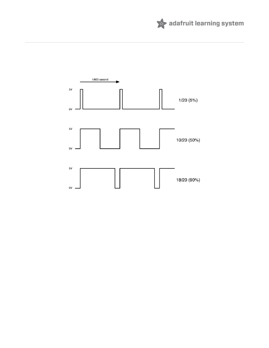
The diagram below shows the signal from one of the PWM pins on the Arduino.
Roughly every 1/500 of a second, the PWM output will produce a pulse. The length of this pulse
is controlled by the 'analogWrite' function. So 'analogWrite(0)' will not produce any pulse at all
and 'analogWrite(255)' will produce a pulse that lasts all the way until the next pulse is due, so
that the output is actually on all the time.
If we specify a value in the analogWrite that is somewhere in between 0 and 255 then we will
produce a pulse. If the output pulse is only high for 5% of the time then whatever we are driving
will only receive 5% of full power.
If however the output is at 5V for 90% of the time then the load will get 90% of the power
delivered to it. We cannot see the LEDs turning on and off at that speed, so to us, it just looks
like the brightness is changing.
© Adafruit Industries
http://learn.adafruit.com/adafruit-arduino-lesson-3-rgb-leds
Page 13 of 14

Other Things to Do
Try putting a ping-pong ball over the LED
Try changing the delays to speed up or slow down the color changing
There are lots of things you can do with RGB LEDs. Check out some of the projects on the
Internet using RGB LEDs and you will find multi-color persistence of vision devices, as well as all
sorts of lighting effects.
About the Author
Simon Monk is author of a number of books relating to Open Source Hardware. The following
books written by Simon are available from Adafruit:
Arduino (http://adafru.it/1019)
30 Arduino Projects for the Evil
Programming the Raspberry Pi (http://adafru.it/aM5)
.
© Adafruit Industries
Last Updated: 2013-06-22 06:46:01 PM EDT
Page 14 of 14
Document Outline
- Guide Contents
- Overview
- Parts
- Breadboard Layout
- Colors
- Arduino Sketch
- Using Internet Colors
- Theory (PWM)
- Other Things to Do
Wyszukiwarka
Podobne podstrony:
adafruit arduino lesson 4 eight leds
adafruit arduino lesson 13 dc motors
adafruit arduino lesson 6 digital inputs
adafruit arduino lesson 16 stepper motors
adafruit arduino lesson 9 sensing light
How to Use RGB LEDs Backlight o Nieznany
ATM18 A String of 160 RGB LEDs
adafruits raspberry pi lesson 3 network setup
lesson4
Lesson15
face painting lesson 3 id 16748 Nieznany
Powerprojekte mit Arduino und C
2 3 Unit 1 Lesson 2 – Master of Your Domain
konspekty gimnazjum Lesson Plan 3
grammar lesson mk
konspekty gimnazjum Lesson Plan Ib
konspekty gimnazjum lesson plan 5
więcej podobnych podstron