Arduino Lesson 4. Eight LEDs and a Shift Register
Created by Simon Monk
Last updated on 2013-06-24 10:15:50 PM EDT

2
3
4
4
4
6
8
10
13
15
Guide Contents
Breadboard Layout
The 74HC595 Shift Register
Arduino Code
Brightness Control
Other Things to Do
© Adafruit Industries
http://learn.adafruit.com/adafruit-arduino-lesson-4-eight-leds
Page 2 of 15
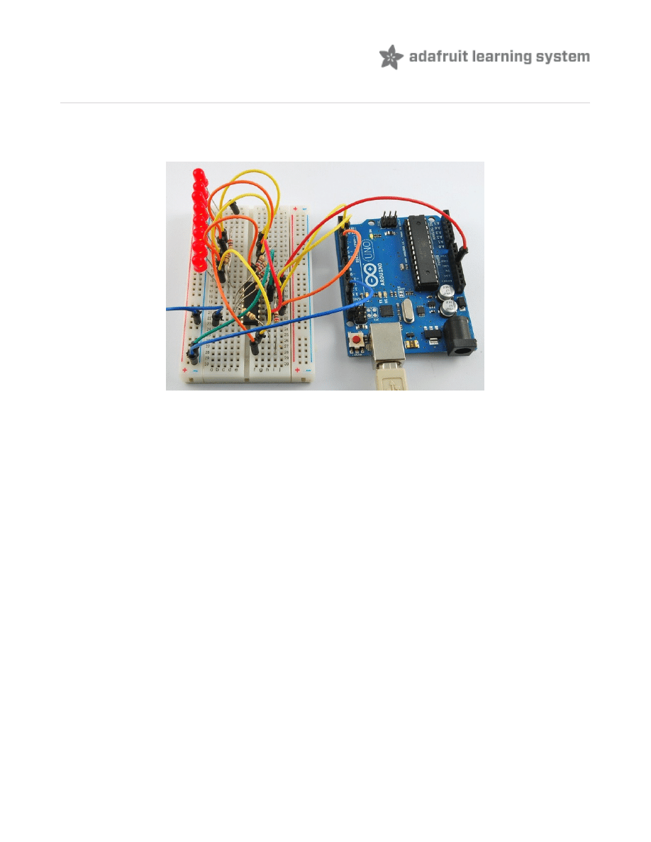
Overview
In this lesson, you will learn how to use eight large red LEDs with an Arduino without needing to
give up 8 output pins!
Although you could wire up eight LEDs each with a resistor to an Arduino pin (like we did for an
RGB LED in Lesson 2) you would rapidly start to run out of pins on your Arduino. If you don't
have a lot of stuff connected to your 'duino it's OK to do so - but often times we want buttons,
sensors, servos, etc and before you know it you've got no pins left. So, instead of doing that,
you are going to use a chip called the 74HC595 Parallel to Serial Converter. This chip
has eight outputs (perfect) and three inputs that you use to feed data into it a bit at a time.
This chip makes it a little slower to drive the LEDs (you can only change the LEDs about 500,000
times a second instead of 8,000,000 a second) but it's still really really fast, way faster than
humans can detect, so it's worth it!
© Adafruit Industries
http://learn.adafruit.com/adafruit-arduino-lesson-4-eight-leds
Page 3 of 15
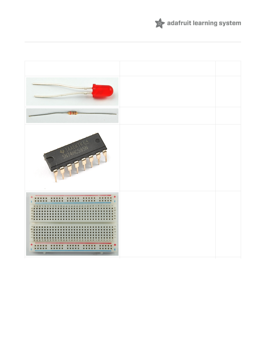
Parts
To build the project described in this lesson, you will need the following parts.
Part
Qty
5mm Red LED
8
270 Ω Resistors (red, purple, brown
stripes)
8
74HC595 Shift Register
1
Half-size Breadboard
1
© Adafruit Industries
http://learn.adafruit.com/adafruit-arduino-lesson-4-eight-leds
Page 4 of 15
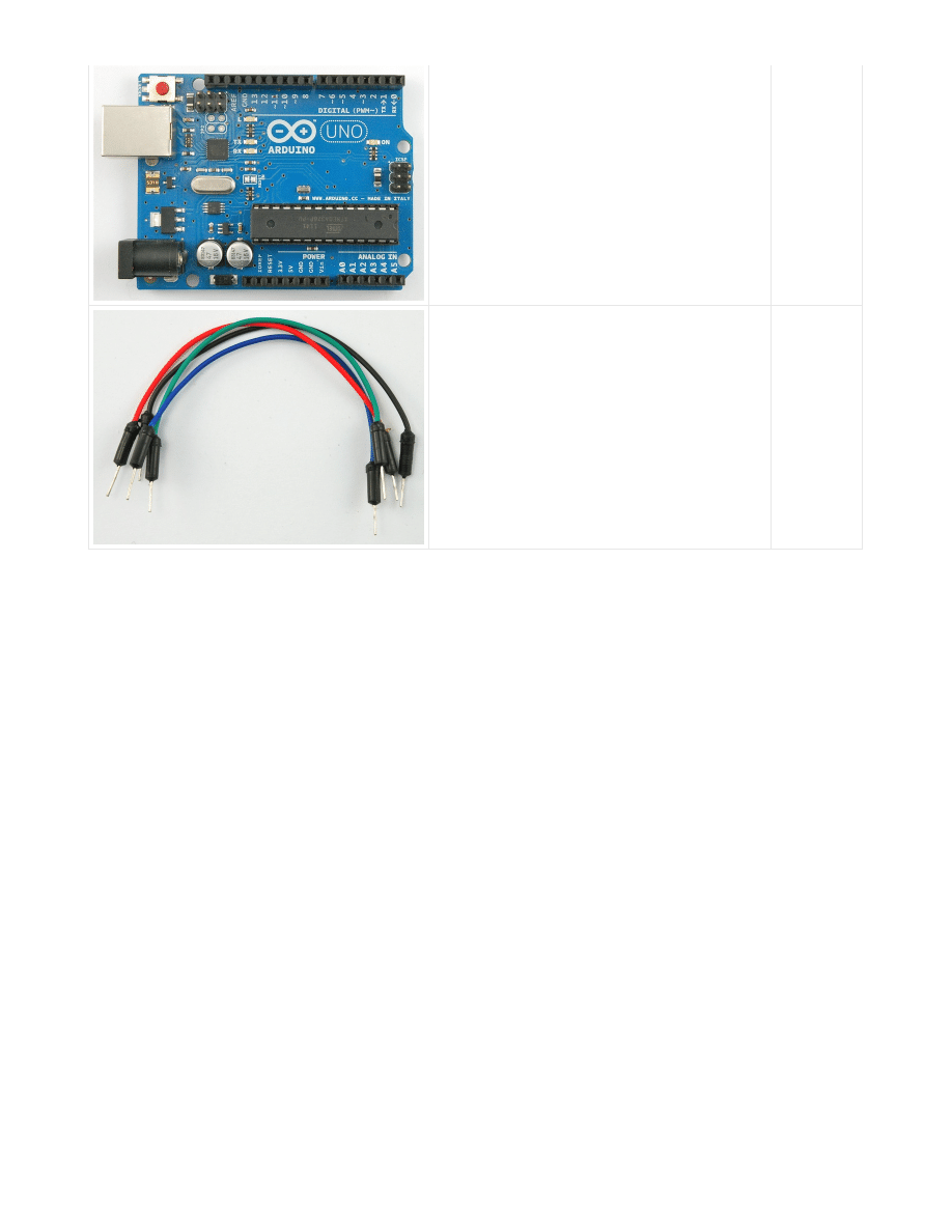
Arduino Uno R3
1
Jumper wire pack
1
© Adafruit Industries
http://learn.adafruit.com/adafruit-arduino-lesson-4-eight-leds
Page 5 of 15
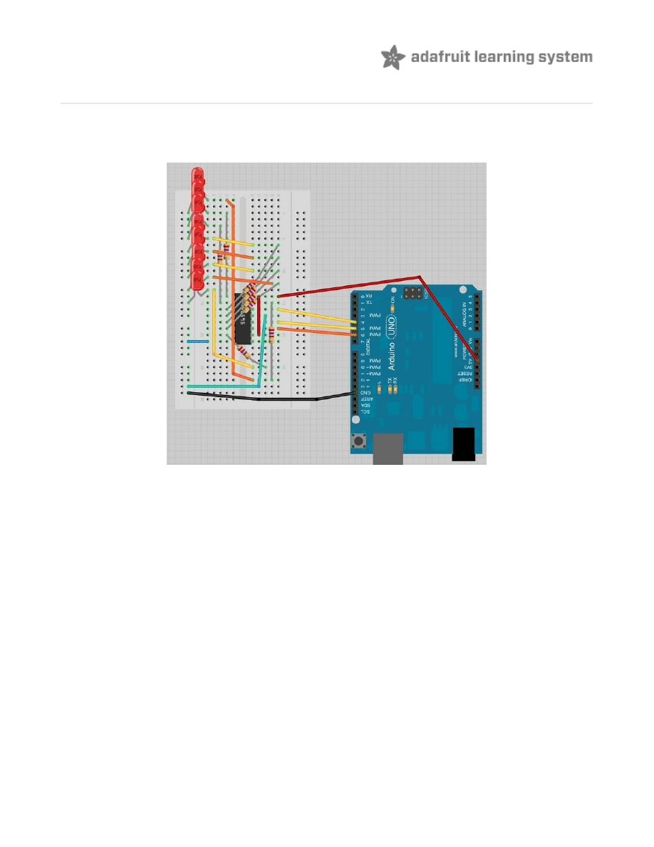
Breadboard Layout
As we have eight LEDs and eight resistors to connect up, there are actually quite a few
connections to be made.
It is probably easiest to put the 74HC595 chip in first, as pretty much everything else connects
to it. Put it so that the little U-shaped notch is towards the top of the breadboard. Pin 1 of the
chip is to the left of this notch.
All but one of the outputs from the '595 are on the left hand side of the chip, hence, for ease of
connection, that is where the LEDs are too.
After the chip, put the resistors in place. You need to be careful that none of the leads of the
resistors are touching each other. You should check this again, before you connect the power
to your Arduino. If you find it difficult to arrange the resistors without their leads touching, then it
helps to shorten the leads so that they are lying closer to the surface of the breadboard.Next,
place the LEDs on the breadboard.
The longer positive LED leads must all be towards the chip, whichever side of the breadboard
they are on.
It now just remains to attach the jumper leads as shown above. Do not forget the one that goes
from pin 8 of the IC to the GND column of the breadboard.
Load up the sketch listed a bit later and try it out. Each LED should light in turn until all the LEDs
are on, and then they all go off and the cycle repeats.
© Adafruit Industries
http://learn.adafruit.com/adafruit-arduino-lesson-4-eight-leds
Page 6 of 15

© Adafruit Industries
http://learn.adafruit.com/adafruit-arduino-lesson-4-eight-leds
Page 7 of 15
The 74HC595 Shift Register
Before I go through the code, let's have a quick look at what the chip is doing, so that we can
understand what the code has to do.
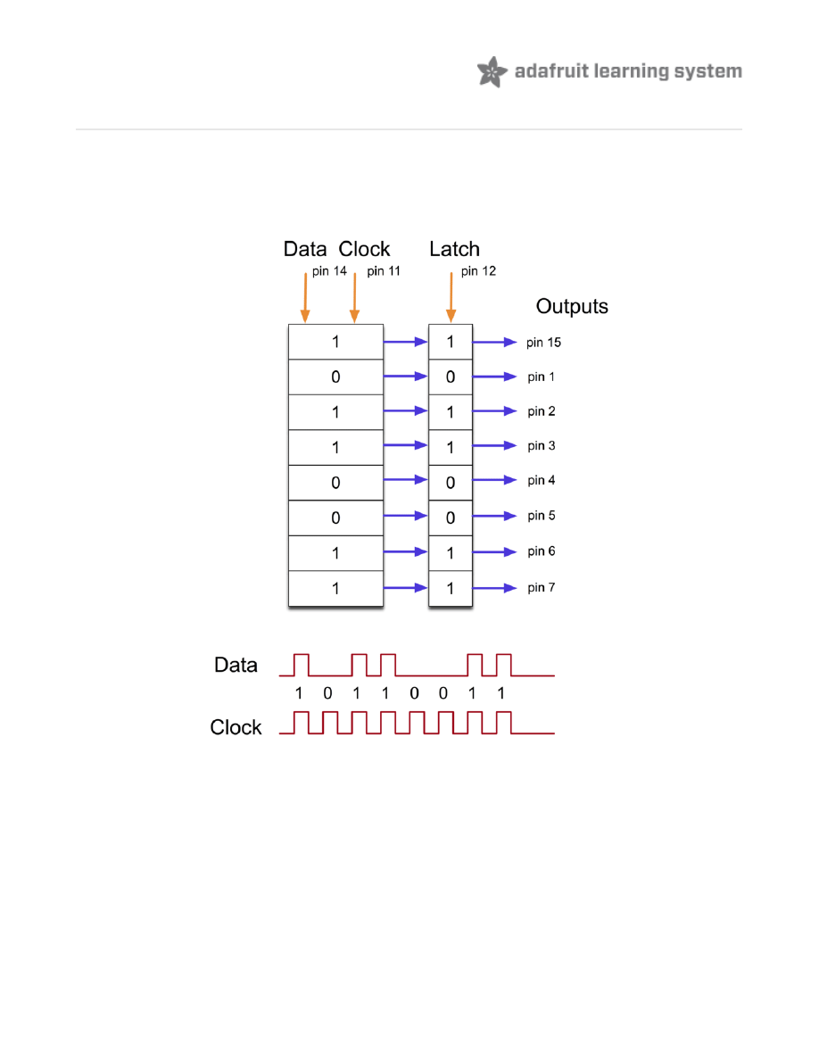
The chip is of a type called a shift register.
The shift register holds what can be thought of as eight memory locations, each of which can
be a 1 or a 0.
To set each of these values on or off, we feed in the data using the 'Data' and 'Clock' pins of
the chip.
The clock pin needs to receive eight pulses, at the time of each pulse, if the data pin is high,
then a 1 gets pushed into the shift register, otherwise a 0. When all eight pulses have been
received, then enabling the 'Latch' pin copies those eight values to the latch register. This is
necessary, otherwise the wrong LEDs would flicker as the data was being loaded into the shift
register.
© Adafruit Industries
http://learn.adafruit.com/adafruit-arduino-lesson-4-eight-leds
Page 8 of 15

The chip also has an OE (output enable) pin, this is used to enable or disable the outputs all at
once. You could attach this to a PWM capable Arduino pin and use 'analogWrite' to control the
brightness of the LEDs. This pin is active low, so we tie it to GND.
© Adafruit Industries
http://learn.adafruit.com/adafruit-arduino-lesson-4-eight-leds
Page 9 of 15
Arduino Code
Arduino includes a special function called 'shiftOut' that is designed specifically for sending data
to shift registers.
Here is the full sketch, the discussion of how it works follows on from it.
The first thing we do is define the three pins we are going to use. These are the Arduino digital
outputs that will be connected to the latch, clock and data pins of the 74HC595.
/*
Adafruit Arduino - Lesson 4. 8 LEDs and a Shift Register
*/
int
latchPin
=
5
;
int
clockPin
=
6
;
int
dataPin
=
4
;
byte
leds
=
0
;
void
setup
()
{
pinMode
(
latchPin
,
OUTPUT
);
pinMode
(
dataPin
,
OUTPUT
);
pinMode
(
clockPin
,
OUTPUT
);
}
void
loop
()
{
leds
=
0
;
updateShiftRegister
();
delay
(
500
);
for
(
int
i
=
0
;
i
<
8
;
i
++)
{
bitSet
(
leds
,
i
);
updateShiftRegister
();
delay
(
500
);
}
}
void
updateShiftRegister
()
{
digitalWrite
(
latchPin
,
LOW
);
shiftOut
(
dataPin
,
clockPin
,
LSBFIRST
,
leds
);
digitalWrite
(
latchPin
,
HIGH
);
}
int
latchPin
=
5
;
int
clockPin
=
6
;
int
dataPin
=
4
;
© Adafruit Industries
http://learn.adafruit.com/adafruit-arduino-lesson-4-eight-leds
Page 10 of 15
Next, a variable called 'leds' is defined. This will be used to hold the pattern of which LEDs are
currently turned on or off. Data of type 'byte' represents numbers using eight bits. Each bit can
be either on or off, so this is perfect for keeping track of which of our eight LEDs are on or off.
The 'setup' function just sets the three pins we are using to be digital outputs.
The 'loop' function initially turns all the LEDs off, by giving the variable 'leds' the value 0. It then
calls 'updateShiftRegister' that will send the 'leds' pattern to the shift register so that all the
LEDs turn off. We will deal with how 'updateShiftRegister' works later.
The loop function pauses for half a second and then begins to count from 0 to 7 using the 'for'
loop and the variable 'i'. Each time, it uses the Arduino function 'bitSet' to set the bit that
controls that LED in the variable 'leds'. It then also calls 'updateShiftRegister' so that the leds
update to reflect what is in the variable 'leds'.
There is then a half second delay before 'i' is incremented and the next LED is lit.
The function 'updateShiftRegister', first of all sets the latchPin to low, then calls the Arduino
function 'shiftOut' before putting the 'latchPin' high again. This takes four parameters, the first
two are the pins to use for Data and Clock respectively.
The third parameter specifies which end of the data you want to start at. We are going to start
with the right most bit, which is referred to as the 'Least Significant Bit' (LSB).
The last parameter is the actual data to be shifted into the shift register, which in this case is
'leds'.
byte
leds
=
0
;
void
setup
()
{
pinMode
(
latchPin
,
OUTPUT
);
pinMode
(
dataPin
,
OUTPUT
);
pinMode
(
clockPin
,
OUTPUT
);
}
void
loop
()
{
leds
=
0
;
updateShiftRegister
();
delay
(
500
);
for
(
int
i
=
0
;
i
<
8
;
i
++)
{
bitSet
(
leds
,
i
);
updateShiftRegister
();
delay
(
500
);
}
}
© Adafruit Industries
http://learn.adafruit.com/adafruit-arduino-lesson-4-eight-leds
Page 11 of 15

If you wanted to turn one of the LEDs off rather than on, you would call a similar Arduino function
(bitClear) on the 'leds' variable. This will set that bit of 'leds' to be 0 and you would then just
need to follow it with a call to 'updateShiftRegister' to update the actual LEDs.
void
updateShiftRegister
()
{
digitalWrite
(
latchPin
,
LOW
);
shiftOut
(
dataPin
,
clockPin
,
LSBFIRST
,
leds
);
digitalWrite
(
latchPin
,
HIGH
);
}
© Adafruit Industries
http://learn.adafruit.com/adafruit-arduino-lesson-4-eight-leds
Page 12 of 15

Brightness Control
One pin of the 74HC595 that I have not mentioned is a pin called 'Output Enable'. This is pin 13
and on the breadboard, it is permanently connected to Ground. This pin acts as a switch, that
can enable or disable the outputs - the only thing to watch for is it is 'active low' (connect to
ground to enable). So, if it is connected to 5V, all the outputs go off. Whereas if it is connected
to Ground, those outputs that are supposed to be on are on and those that should be off are
off.
We can use this pin along with the 'analogWrite' function, that we used back in Lesson 3, to
control the brightness of the LEDs using PWM (also see Lesson 3).
To do this, all you need to do, is to change the connection to pin 13 of the 74HC595 so that
instead of connecting it to Ground, you connect it to pin 3 of the Arduino.
The sketch below, will once all the LEDs have been lit gradually fade them back to off.
/*
Adafruit Arduino - Lesson 4. 8 LEDs and a Shift Register - Brightness
*/
int
latchPin
=
5
;
int
clockPin
=
6
;
int
dataPin
=
4
;
int
outputEnablePin
=
3
;
byte
leds
=
0
;
void
setup
()
{
pinMode
(
latchPin
,
OUTPUT
);
pinMode
(
dataPin
,
OUTPUT
);
pinMode
(
clockPin
,
OUTPUT
);
pinMode
(
outputEnablePin
,
OUTPUT
);
}
void
loop
()
{
setBrightness
(
255
);
leds
=
0
;
updateShiftRegister
();
delay
(
500
);
for
(
int
i
=
0
;
i
<
8
;
i
++)
{
bitSet
(
leds
,
i
);
updateShiftRegister
();
delay
(
500
);
}
for
(
byte
b
=
255
;
b
>
0
;
b
--)
{
setBrightness
(
b
);
delay
(
50
);
© Adafruit Industries
http://learn.adafruit.com/adafruit-arduino-lesson-4-eight-leds
Page 13 of 15

delay
(
50
);
}
}
void
updateShiftRegister
()
{
digitalWrite
(
latchPin
,
LOW
);
shiftOut
(
dataPin
,
clockPin
,
LSBFIRST
,
leds
);
digitalWrite
(
latchPin
,
HIGH
);
}
void
setBrightness
(
byte
brightness
)
// 0 to 255
{
analogWrite
(
outputEnablePin
,
255
-
brightness
);
}
© Adafruit Industries
http://learn.adafruit.com/adafruit-arduino-lesson-4-eight-leds
Page 14 of 15

Other Things to Do
Once you know how to to use the 74HC595 then there are many things you can do with lots of
LEDs. You could try the following:
Make a 'Larson Scanner' scanning lights
as found on the front of KITT in the TV series Knight
Cylons in the series Battle Start
Galactica. (http://adafru.it/aTg)
Make an electronic dice. Arrange 6 of the LEDs as two columns of three LEDs with one LED
in the middle. Hint – take at a look at the Arduino function called 'random'.
One of the great things about the 74HC595 is that you can daisy-chain them to increase the
number of LEDs that you can control. For this and some other pointers for more advanced use
of the 74HC595, take a look at the official Arduino documentation for using 'shiftOut'
http://arduino.cc/en/Tutorial/ShiftOut (http://adafru.it/aTh)
You are going to use much of the same breadboard setup in lesson 5 with a few minor
changes, so do not dismantle it all just yet.
About the Author
Simon Monk is author of a number of books relating to Open Source Hardware. The following
books written by Simon are available from Adafruit:
Arduino (http://adafru.it/1019)
30 Arduino Projects for the Evil
Programming the Raspberry Pi (http://adafru.it/aM5)
.
© Adafruit Industries
Last Updated: 2013-06-24 10:15:52 PM EDT
Page 15 of 15
Document Outline
- Guide Contents
- Overview
- Parts
- Breadboard Layout
- The 74HC595 Shift Register
- Arduino Code
- Brightness Control
- Other Things to Do
Wyszukiwarka
Podobne podstrony:
adafruit arduino lesson 3 rgb leds
adafruit arduino lesson 13 dc motors
adafruit arduino lesson 6 digital inputs
adafruit arduino lesson 16 stepper motors
adafruit arduino lesson 9 sensing light
adafruits raspberry pi lesson 3 network setup
lesson4
Lesson15
face painting lesson 3 id 16748 Nieznany
Powerprojekte mit Arduino und C
2 3 Unit 1 Lesson 2 – Master of Your Domain
konspekty gimnazjum Lesson Plan 3
grammar lesson mk
konspekty gimnazjum Lesson Plan Ib
konspekty gimnazjum lesson plan 5
Crime Fighter The Awful Eight
2009 11 17 arduino basics
Arduino Basic Reference
więcej podobnych podstron