Arduino Lesson 6. Digital Inputs
Created by Simon Monk
Last updated on 2013-07-16 11:15:48 AM EDT

2
3
4
4
4
6
7
9
10
Guide Contents
Breadboard Layout
Arduino Code
Push Switches
Other Things to Do
© Adafruit Industries
http://learn.adafruit.com/adafruit-arduino-lesson-6-digital-inputs
Page 2 of 10
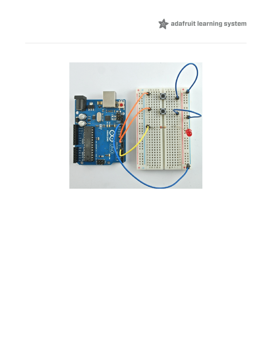
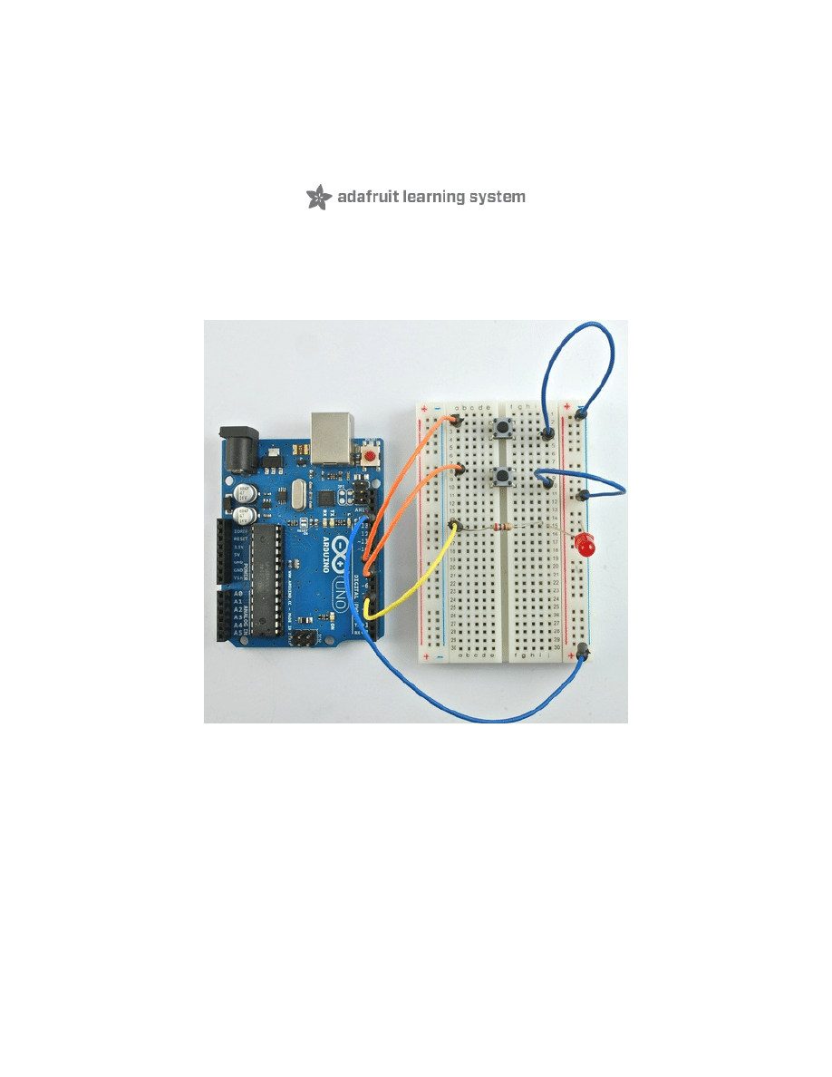
Overview
In this lesson, you will learn to use push buttons with digital inputs to turn an LED on and off.
Pressing the button nearer the top of the breadboard will turn the LED on, pressing the other
button will turn the LED off.
© Adafruit Industries
http://learn.adafruit.com/adafruit-arduino-lesson-6-digital-inputs
Page 3 of 10
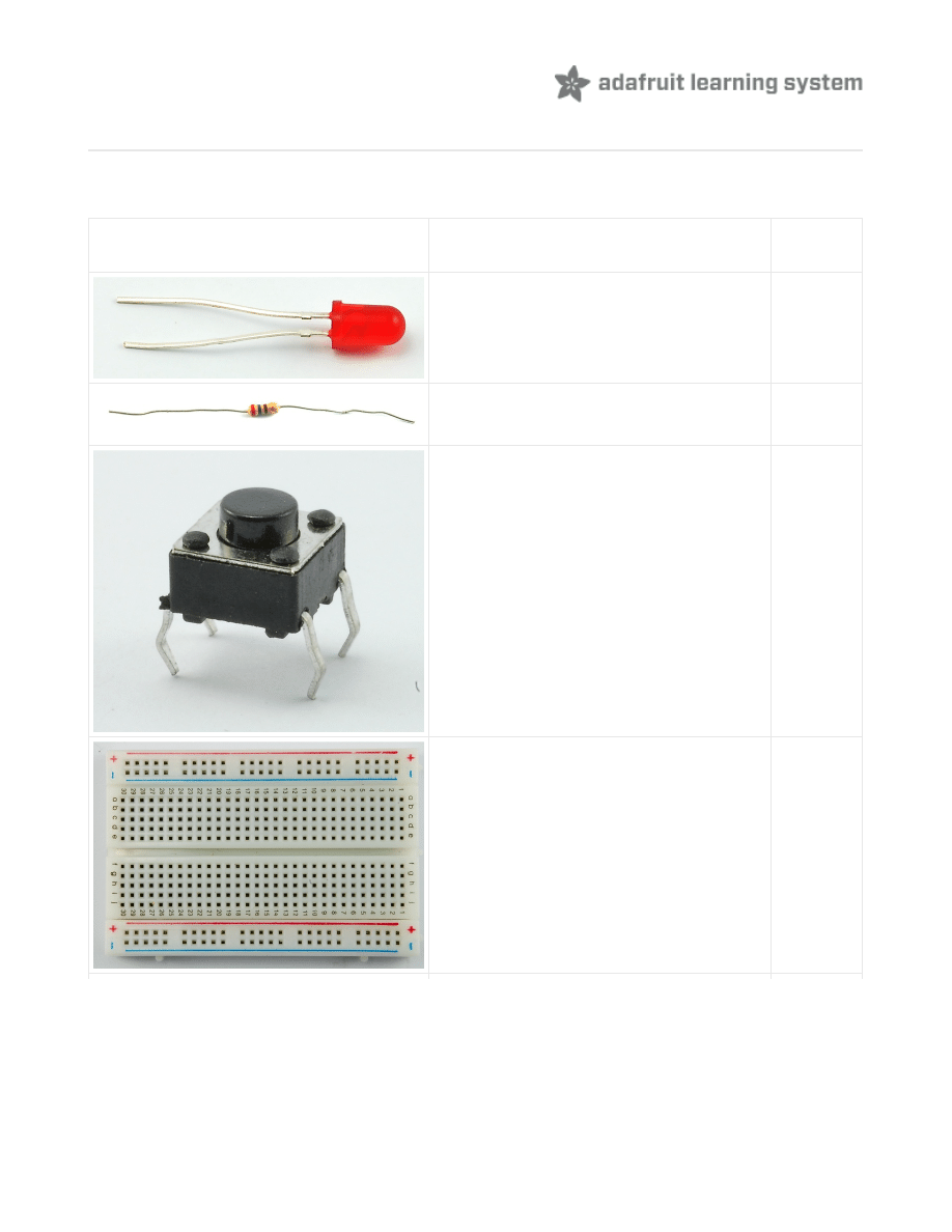
Parts
To complete this lesson, you will need the following parts.
Part
Qty
5mm Red LED
1
270 Ω Resistor (red, purple, brown
stripes)
1
Tactile push switch
2
Half-size Breadboard
1
© Adafruit Industries
http://learn.adafruit.com/adafruit-arduino-lesson-6-digital-inputs
Page 4 of 10
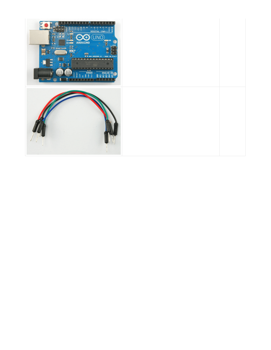
Arduino Uno R3
1
Jumper wire pack
1
© Adafruit Industries
http://learn.adafruit.com/adafruit-arduino-lesson-6-digital-inputs
Page 5 of 10
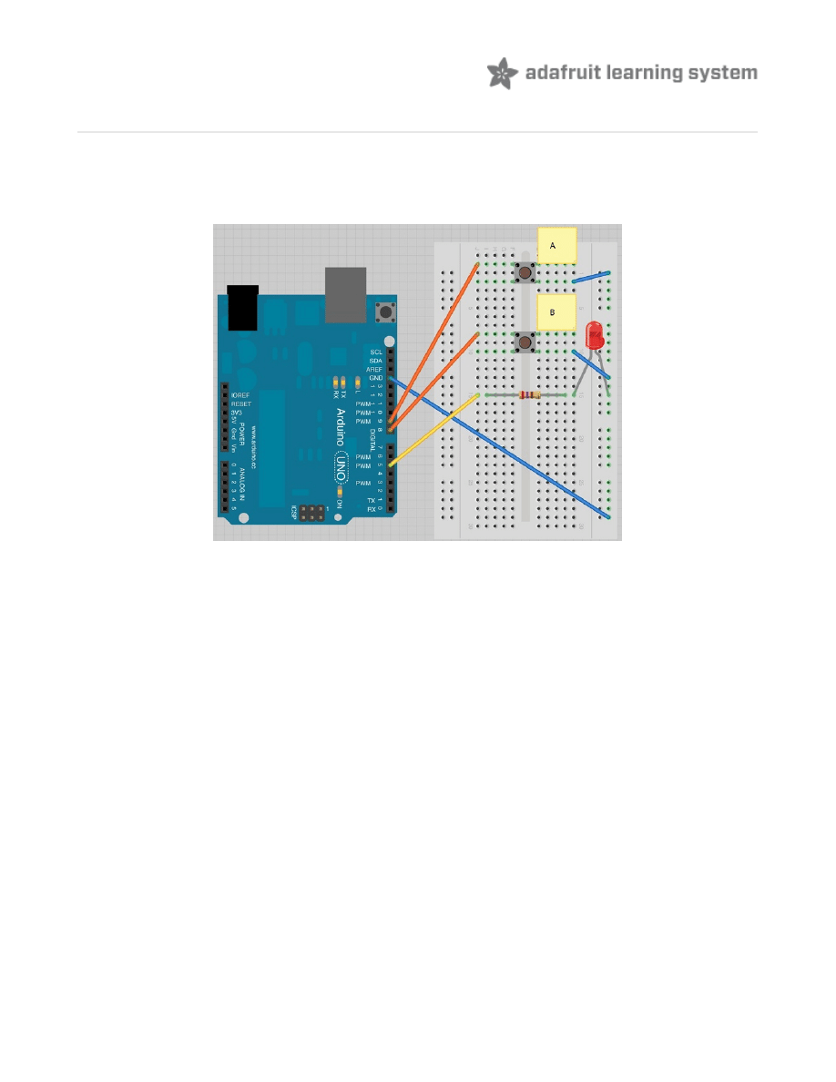
Breadboard Layout
Although the bodies of the switches are square, the pins protrude from opposite sides of the
switch. This means that the pins will only be far enough apart when they are the correct way
around on the breadboard.
Remember that the LED has to be the correct way around with the shorter negative lead to the
right.
© Adafruit Industries
http://learn.adafruit.com/adafruit-arduino-lesson-6-digital-inputs
Page 6 of 10
Arduino Code
Load the following sketch onto your Arduino board. Pressing the top button will turn the LED on,
pressing the bottom button will turn it off again.
The first part of the sketch defines three variable for the three pins that are to be used. The
'ledPin' is the output pin and 'buttonApin' will refer to the switch nearer the top of the
breadboard and 'buttonBpin' to the other switch.
The 'setup' function defines the ledPin as being an OUTPUT as normal, but now we have the two
inputs to deal with. In this case, we use the set the pinMode to be 'INPUT_PULLUP' like this:
The pin mode of INPUT_PULLUP means that the pin is to be used as an input, but that if nothing
else is connected to the input it should be 'pulled up' to HIGH. In other words, the default value
for the input is HIGH, unless it is pulled LOW by the action of pressing the button.
This is why the switches are connected to GND. When a switch is pressed, it connects the input
/*
Adafruit Arduino - Lesson 6. Inputs
*/
int
ledPin
=
5
;
int
buttonApin
=
9
;
int
buttonBpin
=
8
;
byte
leds
=
0
;
void
setup
()
{
pinMode
(
ledPin
,
OUTPUT
);
pinMode
(
buttonApin
,
INPUT_PULLUP
);
pinMode
(
buttonBpin
,
INPUT_PULLUP
);
}
void
loop
()
{
if
(
digitalRead
(
buttonApin
)
==
LOW
)
{
digitalWrite
(
ledPin
,
HIGH
);
}
if
(
digitalRead
(
buttonBpin
)
==
LOW
)
{
digitalWrite
(
ledPin
,
LOW
);
}
}
pinMode
(
buttonApin
,
INPUT_PULLUP
);
pinMode
(
buttonBpin
,
INPUT_PULLUP
);
© Adafruit Industries
http://learn.adafruit.com/adafruit-arduino-lesson-6-digital-inputs
Page 7 of 10
pin to GND, so that it is no longer HIGH.
Since the input is normally HIGH and only goes LOW, when the button is pressed, the logic is a
little up-side-down. We will handle this in the 'loop' function.
In the 'loop' function there are two 'if' statements. One for each button. Each does an
'digitalRead' on the appropriate input.
Remember that if the button is pressed, the corresponding input will be LOW, if button A is low,
then a 'digitalWrite' on the ledPin turns it on.
Similarly, if button B is pressed, a LOW is written to the ledPin.
void
loop
()
{
if
(
digitalRead
(
buttonApin
)
==
LOW
)
{
digitalWrite
(
ledPin
,
HIGH
);
}
if
(
digitalRead
(
buttonBpin
)
==
LOW
)
{
digitalWrite
(
ledPin
,
LOW
);
}
}
© Adafruit Industries
http://learn.adafruit.com/adafruit-arduino-lesson-6-digital-inputs
Page 8 of 10
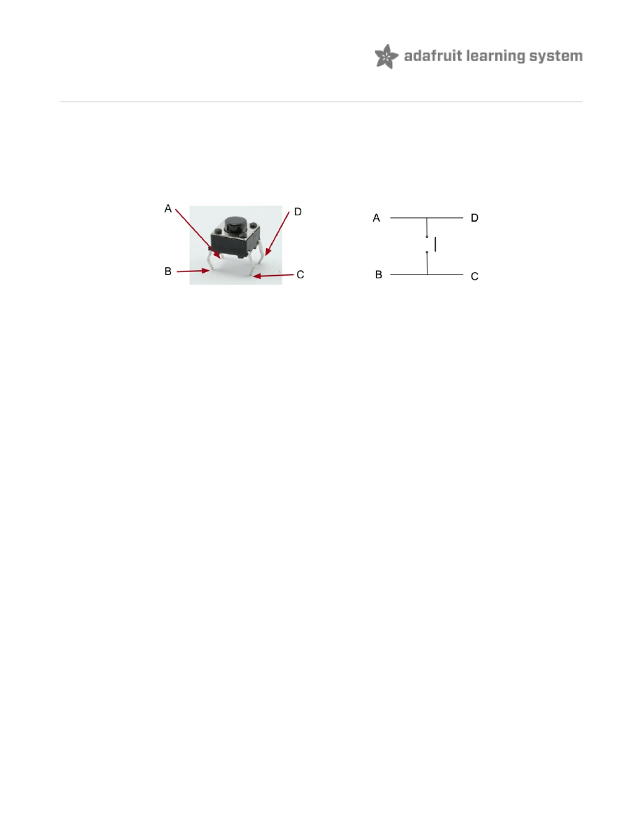
Push Switches
Switches are really simple components. When you press a button or flip a lever, they connect
two contacts together so that electricity can flow through them.
The little tactile switches that are used in this lesson have four connections, which can be a little
confusing.
Actually, there are only really two electrical connections, as inside the switch package pins B
and C are connected together, as are A and D.
© Adafruit Industries
http://learn.adafruit.com/adafruit-arduino-lesson-6-digital-inputs
Page 9 of 10
Other Things to Do
There are a couple of things we could try with this hardware.
Firstly, you could try taking what you learnt in lesson 5 and adding some commands to the
sketch that print something to the Serial Monitor whenever either switch is pressed.
Remember that as well as printing out a message using something like this in your 'loop'
function:
You will also need to start serial communication in the 'setup' function by doing this:
A second modification that you could make would be to make the buttons do something
different. So, for example you could change the sketch so that if button A is pressed, the LED
turns on, but then turns off again after 30 seconds.
Hint: Think of this as being a very slow blink.
About the Author
Simon Monk is author of a number of books relating to Open Source Hardware. The following
books written by Simon are available from Adafruit:
Arduino (http://adafru.it/1019)
30 Arduino Projects for the Evil
Programming the Raspberry Pi (http://adafru.it/aM5)
.
Serial
.
println
(“
Button
A
Pressed
”);
while
(!
Serial
);
Serial
.
begin
(
9600
);
© Adafruit Industries
Last Updated: 2013-07-16 11:15:50 AM EDT
Page 10 of 10
Document Outline
Wyszukiwarka
Podobne podstrony:
adafruit arduino lesson 13 dc motors
adafruit arduino lesson 16 stepper motors
adafruit arduino lesson 3 rgb leds
adafruit arduino lesson 4 eight leds
adafruit arduino lesson 9 sensing light
Ch06 Digital Inputs
adafruits raspberry pi lesson 3 network setup
Quick Digital Thermometer Using Cheap USB to TTL Converter and DS18B20 WITHOUT Arduino or Raspberry
lesson4
Lesson15
face painting lesson 3 id 16748 Nieznany
Principles of Sigma Delta Conversion for Analog to Digital Converters
Page153 Model 2491 2492 2493 Digital Switchboard meter c
DIGITAL OUTPUT ANGULAR ACCELEROMETER 8556
Powerprojekte mit Arduino und C
2 3 Unit 1 Lesson 2 – Master of Your Domain
Digital ECU Tuner III Manual
konspekty gimnazjum Lesson Plan 3
więcej podobnych podstron