
Initial Print Date: 12/04
Table of Contents
Subject
Page
Information/Communication . . . . . . . . . . . . . . . . . . . . . . . . . . . . . . . . . . .5
Introduction . . . . . . . . . . . . . . . . . . . . . . . . . . . . . . . . . . . . . . . . . . . . . . . . . . . .5
Radio Systems . . . . . . . . . . . . . . . . . . . . . . . . . . . . . . . . . . . . . . . . . . . . . . . . .5
Audio Systems . . . . . . . . . . . . . . . . . . . . . . . . . . . . . . . . . . . . . . . . . . . . . . . . .5
Telephone Systems . . . . . . . . . . . . . . . . . . . . . . . . . . . . . . . . . . . . . . . . . . . . .5
Navigation Systems . . . . . . . . . . . . . . . . . . . . . . . . . . . . . . . . . . . . . . . . . . . . .5
Radio and CD changer . . . . . . . . . . . . . . . . . . . . . . . . . . . . . . . . . . . . . . . . . .6
New Features of the System . . . . . . . . . . . . . . . . . . . . . . . . . . . . . . . . . . . . .6
Components . . . . . . . . . . . . . . . . . . . . . . . . . . . . . . . . . . . . . . . . . . . . . . . . . .7
BMW Business Radio-CD . . . . . . . . . . . . . . . . . . . . . . . . . . . . . . . . . . . . . . .7
BMW central information display radio (CID radio) . . . . . . . . . . . . . . . . . .7
Central Information Display . . . . . . . . . . . . . . . . . . . . . . . . . . . . . . . . . . . . . .9
Design of the central information display . . . . . . . . . . . . . . . . . . . . . . . .9
CD Changer . . . . . . . . . . . . . . . . . . . . . . . . . . . . . . . . . . . . . . . . . . . . . . . . . .10
BMW Aerial Systems . . . . . . . . . . . . . . . . . . . . . . . . . . . . . . . . . . . . . . . . . .10
Rod Aerial . . . . . . . . . . . . . . . . . . . . . . . . . . . . . . . . . . . . . . . . . . . . . . . . . . . .11
Aerial Diversity . . . . . . . . . . . . . . . . . . . . . . . . . . . . . . . . . . . . . . . . . . . . . . . .11
Components . . . . . . . . . . . . . . . . . . . . . . . . . . . . . . . . . . . . . . . . . . . . . . . . .11
Rod Aerial . . . . . . . . . . . . . . . . . . . . . . . . . . . . . . . . . . . . . . . . . . . . . . . . . . . .11
System Comparison -Linearity . . . . . . . . . . . . . . . . . . . . . . . . . . . . . . .17
E85 Information and Communication Systems
Revision Date:

Subject
Page
Top Hi-Fi Amplifier . . . . . . . . . . . . . . . . . . . . . . . . . . . . . . . . . . . . . . . . . .21
Front Low-range Speaker (Woofer) . . . . . . . . . . . . . . . . . . . . . . . . . . . .21
High-range Speakers (Tweeters) . . . . . . . . . . . . . . . . . . . . . . . . . . . . . .21
Mid-range Speaker . . . . . . . . . . . . . . . . . . . . . . . . . . . . . . . . . . . . . . . . . .22
Carver Woofers (Low-range Speakers), Rear . . . . . . . . . . . . . . . . . . .22
Carver Woofer Operating Principle . . . . . . . . . . . . . . . . . . . . . . . . . . . .23
System Operation Top Hi-Fi . . . . . . . . . . . . . . . . . . . . . . . . . . . . . . . . . . . .24
Top Hi-Fi with Radio Business-CD, or CID Radio . . . . . . . . . . . . . . .24
New Features . . . . . . . . . . . . . . . . . . . . . . . . . . . . . . . . . . . . . . . . . . . . . . . .27
Advantages of New System . . . . . . . . . . . . . . . . . . . . . . . . . . . . . . . . . . . .28
Components of System . . . . . . . . . . . . . . . . . . . . . . . . . . . . . . . . . . . . . . . .28
Central Information Display . . . . . . . . . . . . . . . . . . . . . . . . . . . . . . . . . . . . .29
CID Control Panel . . . . . . . . . . . . . . . . . . . . . . . . . . . . . . . . . . . . . . . . . . . . .29
Navigation Computer DVD . . . . . . . . . . . . . . . . . . . . . . . . . . . . . . . . . . . . .29
GPS Aerial . . . . . . . . . . . . . . . . . . . . . . . . . . . . . . . . . . . . . . . . . . . . . . . . . . . .30
Wheel Speed Sensor . . . . . . . . . . . . . . . . . . . . . . . . . . . . . . . . . . . . . . . . . .30
Improved Direction . . . . . . . . . . . . . . . . . . . . . . . . . . . . . . . . . . . . . . . . . .31
Improved Map Presentation on the CID . . . . . . . . . . . . . . . . . . . . . . . .31
New Map Presentations . . . . . . . . . . . . . . . . . . . . . . . . . . . . . . . . . . . . .32
Digitized Maps on DVD . . . . . . . . . . . . . . . . . . . . . . . . . . . . . . . . . . . . . .32

Subject
Page

4
E85 Information and Communication Systems
E85 Information and Communication Systems
Model: E85
Production: From Start of Production
After completion of this module you will be able to:
• Understand the operation E85 Audio Systems
• Perform Radio and Navigation Service Modes
• Locate and Identify E85 Audio System Components
• Understand the Operation of the E85 Navigation System
Information/Communication
Introduction
The E85 has soared to be the new dynamic leader in the market segment of premium
roadsters. Its breathtaking design and even sportier handling place it distinctly higher than
the E36/7.
In keeping with its top-of-the-range status, the Z4 offers new features in the field of infor-
mation and communication systems.
Radio Systems
The radios have been redesigned and equipped with a CD drive in line with the vehicle's
premium status. It features a new central information display radio specifically designed
for the menu in the central information display.
Audio Systems
In addition to the "Hi-Fi" audio systems, a "Top Hi-Fi" system is offered in the Z4. This
system satisfies the most demanding requirements with regard to sound quality and
sound impression. This is achieved by the use of Carver low-range speakers or woofers.
This new speaker technology enables high sound pressures and distortion-free basses in
conjunction with compact speaker dimensions.
Telephone Systems
At this time No factory installed phone systems are available in the Z4.
Navigation Systems
A further highlight is the high navigation system. The Z4 is the first BMW roadster
equipped with a display for presenting maps for the navigation system. The navigation
information is shown on a central information display located in the middle of the instru-
ment panel. The central information display features a folding function and is folded away
neatly in the instrument cluster when not in use.
5
E85 Information and Communication Systems
Radio and CD changer
The following radios are available for the E85:
• BMW Business radio-CD
• BMW central information display radio CID radio
All radios are new generation radios (NG radios). The radios feature a K-Bus connection
via which they communicate with other control units.
The AF input (audio signals) of the CD changer was increased from 0.5 V to 2.0 V in
order to increase the signal-to-noise ratio. The new generation radios detect whether
they communicate with a 0.5 V CD changer (old) or a 2.0 V CD changer (new) and switch
over the input accordingly.
A 6-CD changer is additionally available. A radio with a cassette drive is no longer
available for the E85.
New Features of the System
The central information display radio is a new feature on the E85 and serves as the
control panel for the CID. The CID radio combines the radio functions with operation of
the navigation system, on-board computer, DSP amplifier, settings as well as deactivation
of the CID.
6
E85 Information and Communication Systems
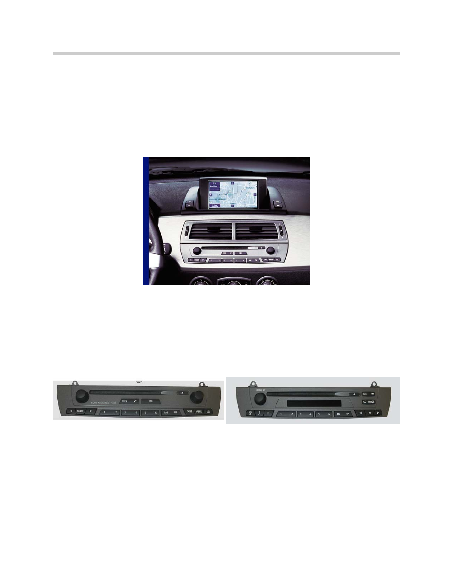
Central Information Radio-CD (CID)
Standard Business Radio-CD
Components
The radios can be optionally fitted at the factory in the following combinations:
• BMW Business Radio-CD
• BMW Central Information Display Radio (CID Radio)
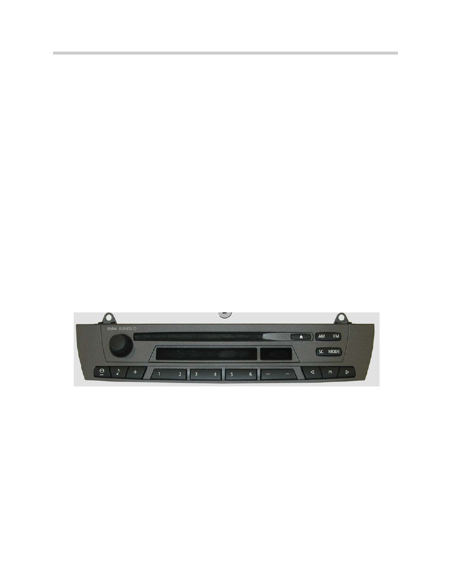
BMW Business Radio-CD
The BMW Business radio-CD can be ordered together with the Hi-Fi or Top Hi-Fi sys-
tem. A CD changer can be additionally connected. In connection with the Hi-Fi audio
system, the BMW Business radio-CD is the standard unit in the US.
The BMW Business radio-CD is a world radio and can be coded for the different regions.
The Business radio-CD is the basic radio in the US version. The radio functions corre-
spond to the previous BMW Business radio. The only difference is in the drive. The radio
is now equipped with a CD drive. The BMW Business radio-CD features aerial diversity.
In the system network, the BMW Business radio-CD facilitates the display and control of
following components:
• CD changer
• Settings for Hi-Fi and Top Hi-Fi
• AUX socket if fitted (option for auxiliary inputs such as MP3 players)
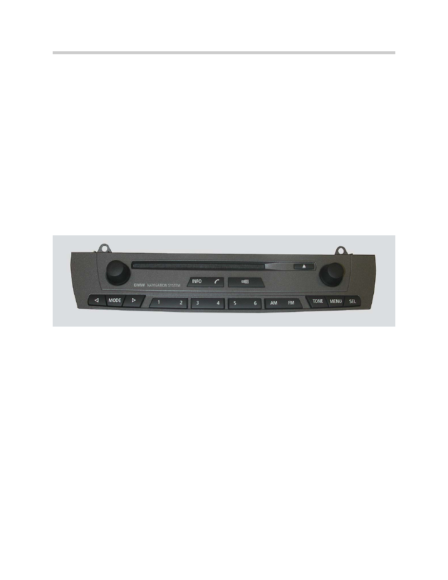
BMW central information display radio (CID radio)
The CID radio is the control panel for the central information display. The CID is the High
navigation system. The CID radio is offered together with a CD. The CID radio can be
ordered together with the Hi-Fi or Top Hi-Fi system. A CD changer can be additionally
connected.
The central information display radio is offered worldwide as the display and operating
unit for the High navigation system. The CID radio consists of the control panel with the
radio functions in the center console and the central information display in the instrument
panel.
The CID radio features a CD drive. A CD changer can be ordered additionally. The CID
radio features aerial diversity.
7
E85 Information and Communication Systems
In the system network, the central information radio facilitates the display and control of
following components:
• Central information display (CID)
• Navigation computer
• CD changer
• Settings for Hi-Fi and Top Hi-Fi
• On-board computer functions
• AUX socket if fitted (option for auxiliary inputs such as MP3 players)
8
E85 Information and Communication Systems
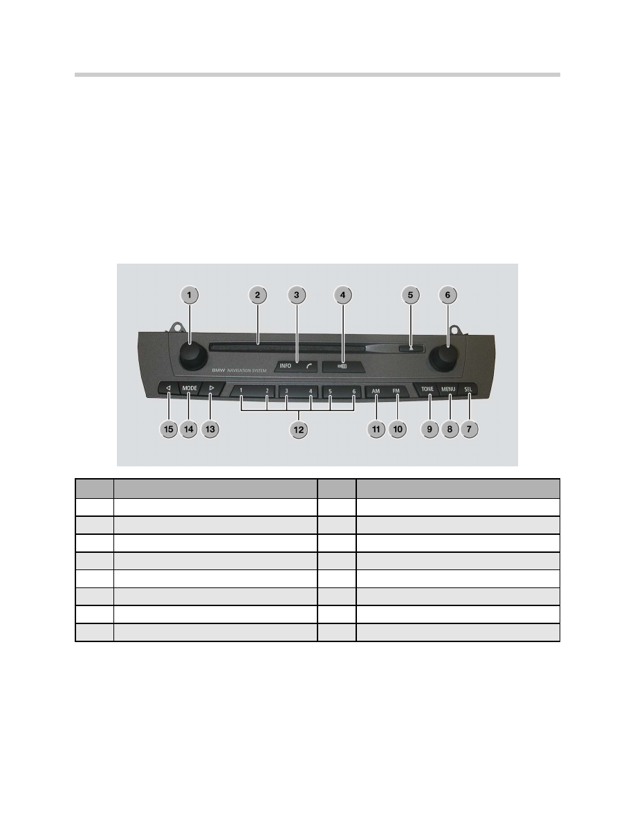
Index
Explanation
Index
Explanation
1
ON/OFF Volume Control
9
Button for Sound Settings
2
CD Compartment
10
FM Button
3
Telephone Acceptance/Info Button
11
AM Button
4
Selector Button for Audio/Last Menu
12
Station Memory Buttons
5
CD Eject Button
13
Forward Scan
6
Push-button/Rotary Knob
14
Mode Button
7
SEL Button
15
Backward Scan
8
Menu Button

Central Information Display
The central information display is located in the center of the instrument panel above the
ventilation outlet.
Design of the central information display
The central information display (CID) includes the following components: advanced
TFT display, crossed-coil motor and mounting with switches.
•
Advanced TFT display - The LC display is designed as a 6.5" advanced TFT
display. The display is of identical design as the 6.5" display of the on-board monitor
in the E46. The advanced TFT display adapts automatically to the brightness of the
ambient light. The display has a visible range of 144 mm x 79.5 mm and a
resolution of 400 x 240 Pixels. The display is an analog unit and is controlled by
RGB signals.
The display is mounted such that it can rotate and is moved by a crossed-coil motor.
•
Crossed-coil motor with gear mechanism (Stepper Motor) - The crossed-coil
motor is a brushless DC motor. The positions of the display are detected by Hall
sensors on the gear mechanism.
•
Mounting - The display and the crossed-coil motor are accommodated in a mount-
ing. The mounting is located in the center of the instrument panel so that the same
component can be used for left-hand drive and right-hand drive vehicles. The
mounting is screwed flush with the surface of the instrument panel.
•
Switch - Left and right switches are integrated in the trough. The left switches
serves the purpose of finely setting the display to improve the readability
corresponding to the seat position and light conditions. The right switch serves to
fold the display in and out.
9
E85 Information and Communication Systems
Index
Explanation
Index
Explanation
1
Screen
4
Switch for Fine Adjustments
2
Switch for Opening/Closing
5
Stepper Motor with Gear Mechanism
3
Mounting
When raised, the position is between 35-108 degrees. The position last stored (last
function memory position) is raised. The display can now be finely adjusted in steps
(1 step = 1.2 degrees) using the left-hand switch. The signal from the switch is sent
directly to the stepper motor and is not transferred via the K-Bus.
Manual fine adjustment of the display is also possible in a range from 35-108 degrees. In
an area below this range (< 35 degrees), the CID is closed automatically as it can no
longer be read effectively in this position. The right-hand switch can be used to close the
display.
Navigation directions are not interrupted if the display is closed while the navigation
system is active. When terminal R is switched off, the CID is always closed and the last
position stored. The display can be switched off by means of a button in the main menu.
If the display is closed manually or electrically while driving, the display will remain closed
at the start of the next trip (last function memory position). The display must first be raised
again by pressing the switch.
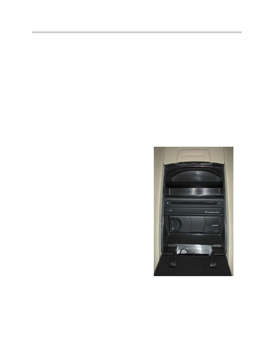
CD Changer
The optional CD changer is the same 6-CD
changer as fitted on the E46. The CD chang-
er is adapted to the new generation radios
and features a 2.0 V AF output.
The CD changer is located in the lockable
compartment in the center of the partition.
The compartment is locked with the central
locking system.
BMW Aerial Systems
The radio aerials for AM/FM are described in
the following. The other aerials are described
in the respective chapters.
The E85 features the following aerial systems:
• Rod aerial for AM/FM
• FM aerial in rear bumper
• GPS aerial for navigation system
10
E85 Information and Communication Systems
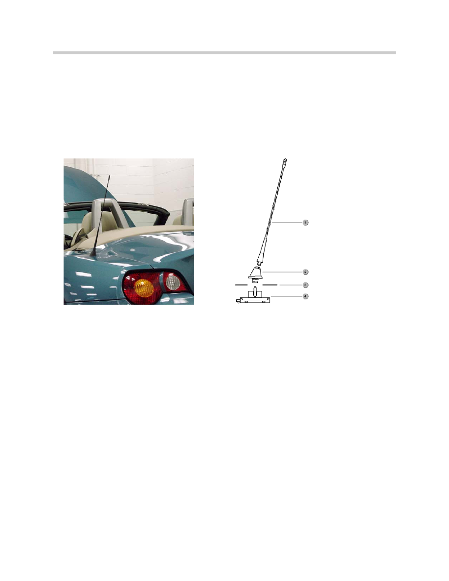
Rod Aerial
The rod aerial is a common part from the E46 convertible. The aerial is designed for
AM/FM reception and additionally features an integrated telephone aerial.
The rod aerial is mounted on the rear left side panel. The aerial amplifier is screwed to
the aerial from below.
The rod aerial consists of the aerial rod, aerial head and aerial base with integrated
aerial amplifier.
Aerial Diversity
The E85 features aerial diversity for the higher grade radios. Aerial diversity comprises
following components:
• Rod aerial with amplifier
• FM aerial in bumper
• FM aerial amplifier
• Aerial diversity
The aerial amplifier and aerial diversity are fitted in the rear left of the luggage compart-
ment. The second FM aerial is located on the rear left in the bumper.
Components
The aerial diversity system includes the rod aerial with amplifier and the FM aerial in
the bumper.
Rod Aerial
The rod aerial is identical to that of the E46 convertible. The rod aerial is designed for
the following wavebands: AM 522 kHz - 1710 kHz and FM 87.5 MHz - 108 MHz.
11
E85 Information and Communication Systems
1. Aerial Rod
2. Aerial Head
3. Body Panel
4. Aerial Amplifier
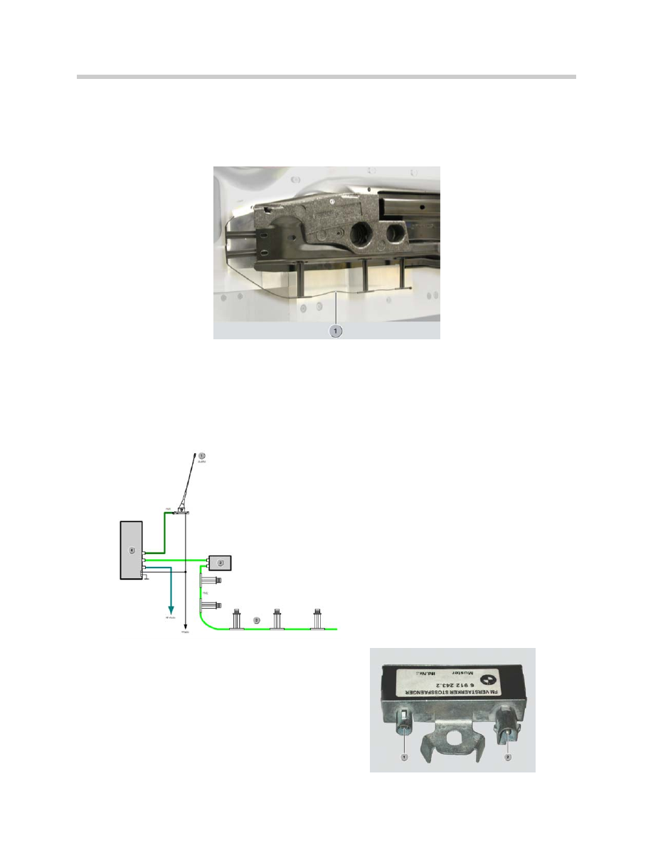
FM Aerial in Bumper
The FM aerial consists of a 73 cm long line. The FM aerial is mounted in the bumper on
adjustable clips. The FM aerial is adapted precisely to the vehicle. For this reason, no
changes must be made to the aerial. The FM aerial is connected to an aerial amplifier.
Aerial Diversity
In the E85, 2 physical aerials are connected to the radio aerial diversity, i.e. the rod aerial
and the aerial in the bumper. The aerial diversity function switches over to another aerial
as soon as the system undershoots a defined threshold. Changeover takes place in such
a way that no interruption can be heard. Depending on the reception situation, reception
on both aerials simultaneously is also possible.
Aerial Amplifier
The aerial amplifier is designed for FM
reception. The aerial amplifier is connected
to the aerial diversity by means of a coaxial
cable.
12
E85 Information and Communication Systems
1. AM/FM Radio Aerial
2. FM Aerial Amplifier
3. FM Aerial in Bumper (in LR bumper)
4. Aerial Diversity (in LR Trunk)

Service Mode for Radios
Service mode is used for a quick check of the most important radio functions. In the
event of a customer complaint or malfunction, several important functions can be
checked directly at the radio with the aid of the service function. It is necessary to access
service mode for this purpose.
Service Mode for Business-CD
• Switch on radio
• Press the "m" button within 8 seconds and hold for at least 8 seconds
• The functions listed in the following table are now possible via the service menu
• Switch off the radio to exit service mode
Service Mode for Radios CID
• Switch on radio
• Press the "SEL" button within 8 seconds and hold for at least 8 seconds
• The functions listed in the following table are now possible via the service menu
• Switch off the radio to exit service mode
Notes for Service
FM Aerial
The FM aerial must be checked in the event of damage to the bumper (accident).
The aerial line must neither be shortened nor lengthened.
The correct position of the spacers for the aerial must be ensured. The aerial is matched
to the metallic body structure. Changes to the body structure greatly influence the aerial
function.
13
E85 Information and Communication Systems
Menu
Screen Contents
Explanation
Serial Number
X1001035
Serial number of Device
Software Version
37-99 30
Software Status WW/YY version
GAL
1-6
Stage of speed dependent volume adjustable with
station buttons.
FM
Frequency
Station Identifier
F....
Q...
D210
Frequency of station
Station identifier being received
Field Strength
Quality of Station
RDS Identifier
DSP
0
Whether vehicle is equipped with DSP 1=DSP
TP Volume
0
Not used in USA
AF (Alternate Frequencies)
Auto
Not used in USA
Area
USA
2 = USA
Index
03
Revision Index

Diagnosis
Diagnosis of the radio without CID comprises the following:
• Read identification
• Read fault code memory
• Delete fault code memory
• Activate components, e.g. button functions, individual channels
• Diagnosis query, e.g. field strength, setting of speed dependent volume control
Coding
Coding in the radio comprises the following functions:
• New coding (country-specific functions)
• Retrofitting
• Conversion
Car & Key Memory
The following functions can be stored in the car & key memory:
• Sound settings
• Audio source
• The last station is stored
Notes:
14
E85 Information and Communication Systems

Classroom Exercise - Review Questions
1.
What are the 2 audio system offered in the E85?
2.
In the event of a customer complaint regarding radio reception issues, what are
some of the steps in diagnosing this complaint?
3.
Where are the FM aerials located on the E85?
4.
What are the two radios offered on the E85?
15
E85 Information and Communication Systems

Audio Systems
The following audio systems are available for the E85:
• Hi-Fi audio system
• Top Hi-Fi audio system
New Features
For the first time at BMW, binding audio standards have been defined for the E85 which
will also be adopted in successor models. In addition to the minimum requirements relat-
ing to the systems, Carver speaker technology is used for the first time worldwide in a
motor vehicle (Top Hi-Fi audio system). This system achieves substantial improvements
in the low frequency range.
The audio standards stipulate the following requirements:
• Classification in 2 audio systems: Hi-Fi and Top Hi-Fi
• Symmetry of sound field: All systems ensure uniform distribution of the sound field
in the vehicle and convey the overall acoustic impression that the source of the
music is in front of the driver and passenger.
• Sound pressure
• Linearity of stereo signal
With the aid of the Carver speaker technology, high sound pressures can be achieved
although there is only a low resonance volume (space behind the speakers) available in
the roadster.
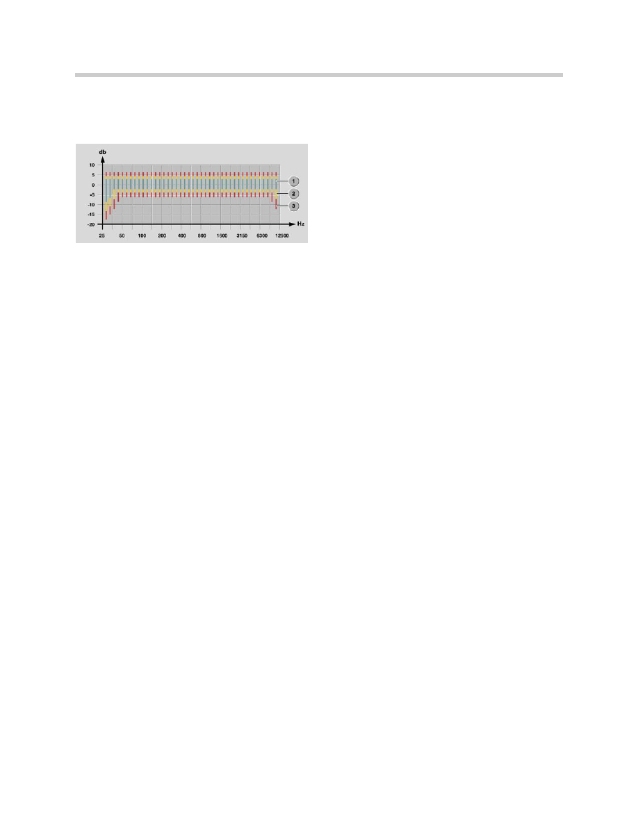
System Comparison - Sound Pressure
The sound pressure in the vehicle is the measure for establishing the total volume up to
which distortion-free sound reproduction is possible.
The higher the sound pressure the greater the volume. When the sound pressure is
increased by approximately.10 dB, the volume is subjectively doubled.
16
E85 Information and Communication Systems
1. Top Hi-Fi
2. Hi-Fi
3. Stereo (not in US)
System Comparison -Linearity
A frequency response as linear as possible is the prerequisite for sound reproduction true
to the original.
Advantages of the Systems
The following advantages characterize the 2 new audio systems:
• Compared to the E36/7, distinct improvements in the low frequency range have
been achieved.
• Due to the dynamically set parameters (adaptive filters) of the Top Hi-Fi amplifier, the
sound impression is adapted to the driving noise characteristic of a roadster.
• The Hi-Fi and Top Hi-Fi audio systems can be combined with virtually all radios.
Hi-Fi System
The Hi-Fi audio system consists of following components:
• Radio Business-CD or CID
• Hi-Fi amplifier
• Front left and right low-range speakers (woofers)
• Front left and right high-range speakers (tweeters)
• Front left and right mid-range speakers
• Rear left and right low-range speakers (woofers)
• Rear left and right mid-range speakers
• CD changer (optional)
Hi-Fi Amplifier
The Hi-Fi amplifier is designed as an analogue 10-channel amplifier. The 4 input chan-
nels are divided via frequency gates and equalizing filters over 10 channels. The Hi-Fi
amplifier is installed in the luggage compartment trough next to the vehicle battery.
The output power is:
• Low-range 4x40 W
• High range/mid-range 6x25 W
The channels are divided over a 3-way speaker system at the front and a 2-way speaker
system at the rear.
17
E85 Information and Communication Systems
1. Top Hi-Fi
2. Hi-Fi
3. Stereo (not in US)
Speakers
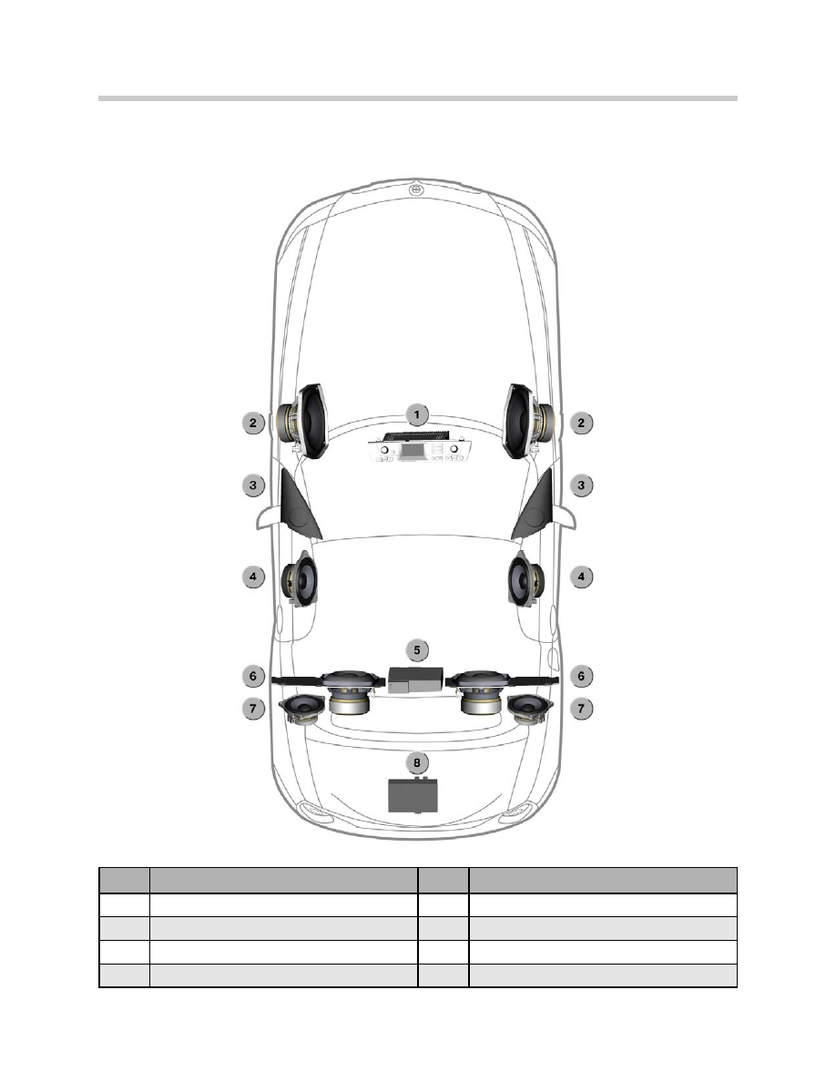
18
E85 Information and Communication Systems
Index
Explanation
Index
Explanation
1
Radio
5
CD Changer (optional)
2
Low-range speaker, front
6
Low-range speaker, rear
3
High-range speaker, front
7
Mid-range speaker, rear
4
Mid-range speaker, front
8
Hi-fi amplifier
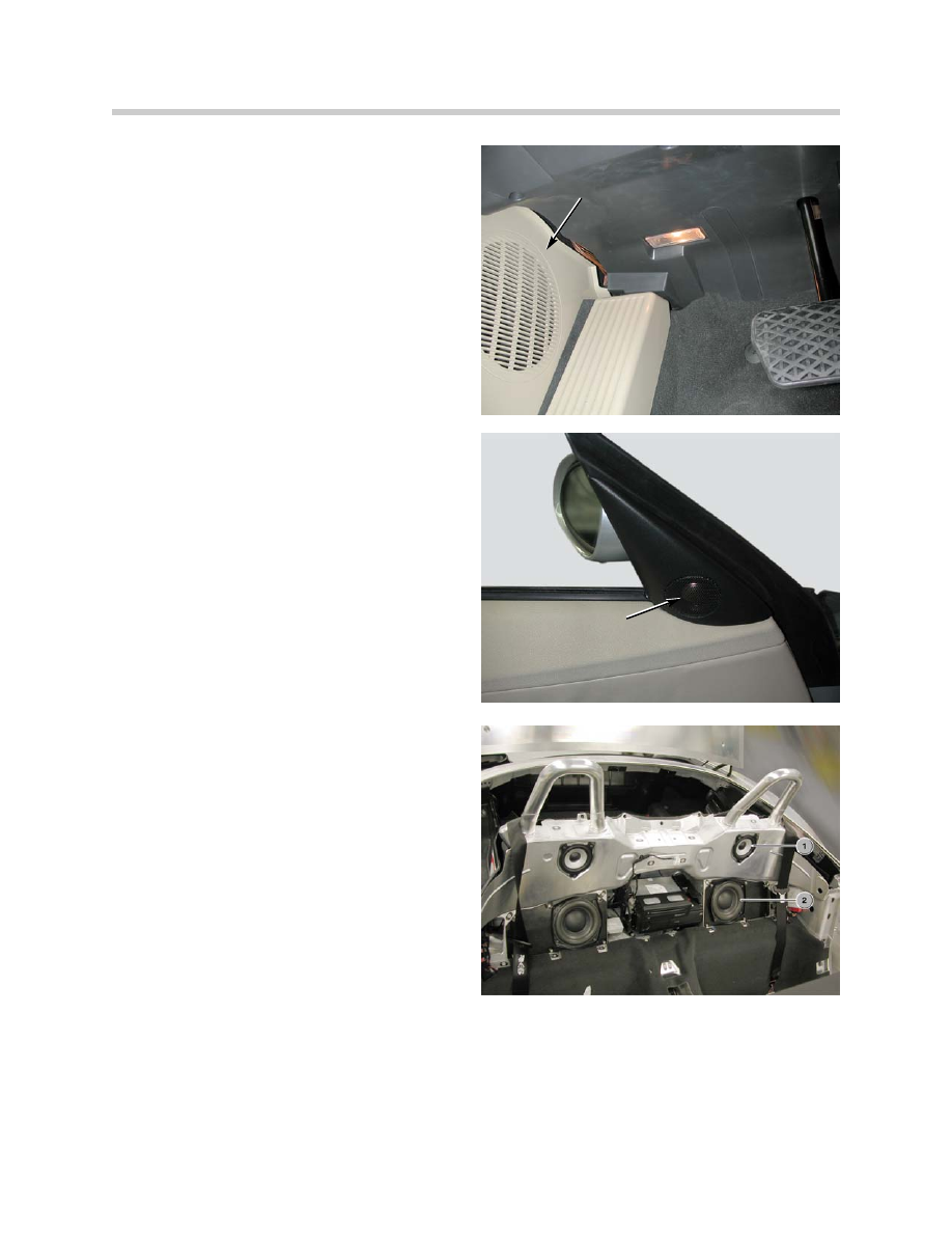
Low-range Speakers (Woofers)
The front woofers (low-range speakers) are
mounted at the bottom in the A-pillars on
the left and right. The woofers are arranged
transversely with respect to forward direc-
tion. The resonance volume is approxi-
mately.10 l and utilizes a part of the sill area.
Rear woofers are additionally installed in the
partition behind the seats.
High-range Speakers (Tweeters)
The tweeter has a diameter of 26 mm and
has a fabric cap. The maximum load
capacity is 25 W. The tweeter (high-range
speaker) covers a frequency range from
4000 Hz to 20,000 Hz. The tweeter is
connected to the woofer.
The frequency range of the high-range
speaker is set by means of a capacitor.
The tweeter (high-range speaker) is located
in a panel mounted in the mirror triangle.
The output direction of the tweeter is
directed at the head area of the occupant
opposite. The tweeter (high-range speaker)
is based on a sealed design.
Mid-range Speakers
The mid-range speakers have a diameter of
100 mm and a paper cone. The maximum
load capacity is 25 W. The mid-range
speaker covers a frequency range from 100
Hz to 15,000 Hz. The front and rear mid-
range speakers are of identical design.
The front mid-range speakers are fitted in
the doors. The rear mid-range speakers
are mounted behind the seats. The front
mid-range speakers emit sound transverse-
ly with respect to forward direction. The
mid-range speakers utilize the resonance
volume of the doors. The output of the rear
mid-range speakers is aligned in forward
direction. The resonance volume is approxi-
mately 2 liters.
19
E85 Information and Communication Systems
Low Range Speaker
(in footwell)
High Range Speaker
(tweeter)
1. Rear Mid-Range Speaker
2. Rear Woofers
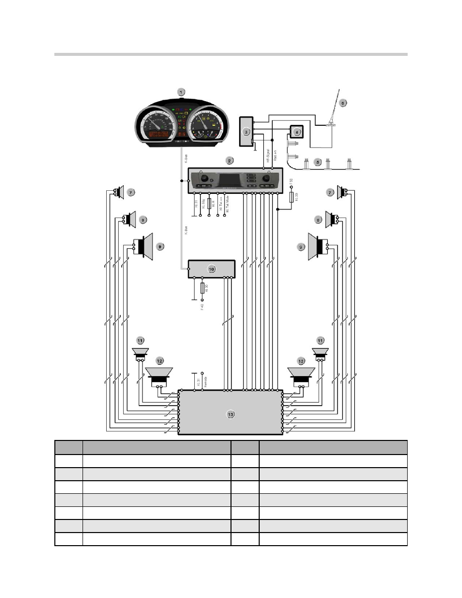
Hi-Fi System Overview
20
E85 Information and Communication Systems
Index
Explanation
Index
Explanation
1
Instrument Cluster
8
Mid-Range Speaker Front
2
Radio
9
Low-Range Speaker Front
3
FM Aerial Diversity
10
CD Changer
4
FM Amplifier
11
Mid-Range Speaker Rear
5
FM Aerial #2
12
Low-Range Speaker Rear
6
AM/FM Aerial #1
13
Hi-FI Amplifier
7
High-Range Speaker Front
Top Hi-Fi System
The Top Hi-Fi audio system consists of following components:
• Radio Business-CD or CID
• Top Hi-Fi amplifier
• Front left and right low-range speakers (woofers)
• Front left and right high-range speakers (tweeters)
• Front left and right mid-range speakers
• Rear left and right mid-range speakers
• Rear left and right low-range speakers (woofers) in Carver technology
• CD changer (optional)
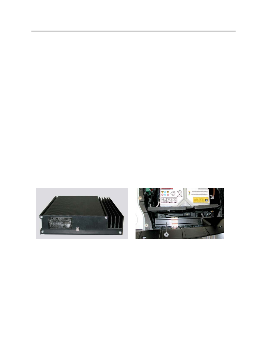
Top Hi-Fi Amplifier
With regard to its functionality, the Top Hi-Fi amplifier corresponds to the previous DSP
amplifier as already used in other model series. The special features on the E85 are the
two high voltage output stages (30 V) for the Carver woofers.
The Top Hi-Fi amplifier has 2 analogue inputs (left and right). In addition, the Top Hi-Fi
amplifier features a digital input for the CD changer connection (coaxial cable). This
arrangement achieves a higher signal quality.
The Top Hi-Fi amplifier is installed in the luggage compartment next to the vehicle battery.
Front Low-range Speaker (Woofer)
The woofer has a diameter of 160 mm and a paper cone. The maximum load capacity is
50 W. The woofers (low-range speakers) cover a frequency range from 50 Hz to 500 Hz.
The front woofers (low-range speakers) are mounted at the bottom in the A-pillars on the
left and right.
High-range Speakers (Tweeters)
The tweeter has a diameter of 26 mm and a fabric cap or calotte. The maximum load
capacity is 25 W. The tweeter (high-range speaker) covers a frequency range from 4000
Hz to 20,000 Hz.
The frequency range of the high-range speaker is set by means of a capacitor.
21
E85 Information and Communication Systems
The tweeter (high-range speaker) is located in a panel mounted in the mirror triangle.
The output direction of the tweeter is directed at the head area of the occupant opposite.
The tweeter (high-range speaker) is based on a sealed design.
Mid-range Speaker
The mid-range speaker has a diameter of 100 mm and an aluminum cone. The maxi-
mum load capacity is 50 W. The mid-range speaker covers a frequency range from 100
Hz to 10,000 Hz. The front and rear mid-range speakers are identical.
The front mid-range speakers are fitted in the doors. The rear mid-range speakers are
installed in the partition behind the seats.
Carver Woofers (Low-range Speakers), Rear
The Carver woofers have a diameter of 160 mm and a paper cone in Carver technology.
The maximum load capacity is 100 W. The Carver woofers cover a frequency range from
30 Hz to 150 Hz.
The rear Carver woofers are accommodated in the partition behind the seats, the
resonance volume is approximately 10 liters.
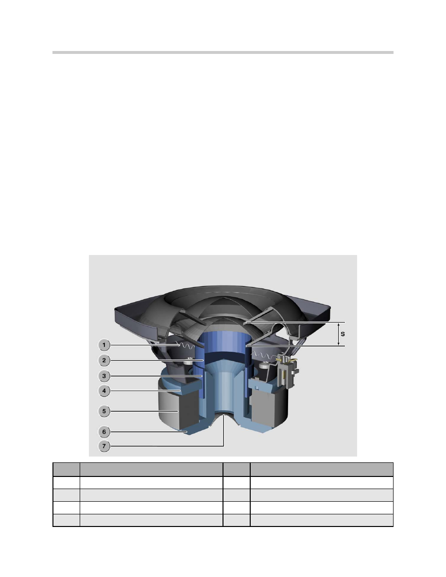
22
E85 Information and Communication Systems
Index
Explanation
Index
Explanation
1
Centering Swing Arm
5
Permanent Magnet
2
Displacement Cylinder
6
Iron Core
3
Moving Coil
7
Ventilation Hole
4
Pole Core
8
Diaphragm Displacement

Carver Woofer Operating Principle
High sound pressure is required for achieving a rich bass. The Carver woofers (low-range
speakers) produce this sound pressure with their small diameter by increasing the
displacement of the diaphragm. The sound pressure is produced by movement in the
volume of air.
The volume of air moved is derived from the diaphragm area multiplied by the displace-
ment. To date to achieve this, the largest possible diaphragm area (diameter of the
speaker) was used in conjunction with relatively low displacement (approximately. 3-10
mm). A matching resonance volume is additionally required.
In vehicle construction applications, this technology leads to a conflict between vehicle
design and vehicle equipment: Due to the design and comprehensive level of equipment,
there is little package space available for large bass speakers.
Carver technology represents a new approach in solving this problem. Thanks to Carver
technology, a high sound pressure is produced with a small speaker diameter by increas-
ing the diaphragm displacement (approximately. 30 mm).
Due to the greater diaphragm displacement Carver woofers (low-range speakers) require
a higher voltage supply than conventional speakers.
A special DSP amplifier with high voltage output stages (30 Vrms) is required for the Top
Hi-Fi audio system. It is necessary to greatly increase the magnetic force in order to
achieve greater diaphragm displacement. The solenoid was adapted accordingly. A high
magnetic force also means that a high back emf is produced in the solenoid (back emf
Uemf=B.l.v).
The back emf counteracts the output voltage of the amplifier thus reducing the effective
voltage at the solenoid.
It is not possible to operate Carver speakers with the amplifiers (radio output stages
6 Vrms) previously used.
23
E85 Information and Communication Systems

System Operation Top Hi-Fi
The Top Hi-Fi audio system features a 10-channel analogue amplifier with DSP technolo-
gy as used in the current vehicles. The Top Hi-Fi amplifier is controlled with a constant
audio signal via the two analogue output channels of the radio. In addition, the Top Hi-Fi
amplifier features a digital input for the CD changer. The speakers are connected to the
10 output channels.
The Top Hi-Fi audio system has following output ratings:
• Medium-range and high-range speakers: 6x20 W
• Low-range speakers: 2x40 W
• Carver low-range speakers: 2x100 W
Top Hi-Fi with Radio Business-CD, or CID Radio
Depending on the type of radio installed, programmed sound settings can be selected or
freely programmed. In connection with the radio Business-CD, one of the following 3
programmed sound settings can be selected in the "Tone" (sounds) menu:
• Jazz
• Hall
• Cathedral
The radio CID radio with the central information display offers the following features:
• 3 preset menus (see above)
• 3 freely programmable menus
In the case of the CID radio, the overall acoustics can be set individually by means of
a 7-band graphic equalizer.
24
E85 Information and Communication Systems

Principle of Operation
All audio systems are controlled via the radio. The differences between the systems are
in the control of the amplifiers. The Hi-Fi and Top Hi-Fi amplifiers do not feature direct
control functions.
Hi-Fi Amplifier
The Hi-Fi amplifier is controlled via the radio.
The required settings are selected in the radio and output via 4 radio outputs to the
amplifier. The amplifier amplifies the settings and distributes them over 10 channels.
No variable matching takes place in the Hi-Fi amplifier. Vehicle-specific equalizing is inte-
grated in the Hi-Fi amplifier.
The following functions can be set in the radio:
• Volume
• Bass
• Treble
• Balance (left/right)
• Fader (front/rear)
• Loudness
• Speed-dependent volume control
Top Hi-Fi Amplifier
The Top Hi-Fi amplifier is also controlled via the radio. The Top Hi-Fi amplifier receives a
constant audio signal for the left and right (via the two audio inputs) from the radio. The
required settings are transferred via the K-Bus and formed in the amplifier.
The following functions can be set:
• Volume
• Bass
• Treble
• Balance (left/right)
• Fader (front/rear)
In addition, the overall acoustics can be set individually (CID only) by means of a 7-band
graphic equalizer.
25
E85 Information and Communication Systems

Improved Overall Acoustic Impression
With the aid of software, adaptations were implemented in the Top Hi-Fi amplifier for the
purpose of improving the overall acoustic impression.
The following adaptations in the amplifier are conducted automatically:
• Loudness
• Speed-dependent volume control
• Vehicle-specific equalizing
• Dynamic equalizing
• Dynamic compression
• Internal temperature monitoring
Loudness
To improve the listening nuance, the low frequencies are raised slightly at low volume
settings.
Speed-dependent Volume Control
The volume is raised as the driving speed increases. 6 characteristic curves are available
for this purpose. The characteristics can be set individually in the service functions.
Vehicle-specific Equalizing
The acoustics are matched to the vehicle interior.
Dynamic Equalizing
The acoustics are adapted to increasing driving noise.
Dynamic Compression
The dynamics must be compressed to avoid overloading the system. The upper level of
effective dynamics is limited by the output power of the amplifier and the load capacity of
the speakers. For this reason, the speed-dependent volume cannot be increased
infinitely,
Internal Temperature Monitoring
In the event of excessively high temperature, the output of the output stages is reduced in
order to cool them. The temperature of the output stages is permanently monitored.
Notes for Service
Diagnosis
No diagnosis functions are provided for the audio systems.
Coding
No variant coding functions are provided for the audio systems.
Car & Key Memory
No functions are available for the car & key memory.
26
E85 Information and Communication Systems
Navigation
New Features
For the first time for a roadster, a High version navigation system with map presentation
on a display has been developed for the E85.
27
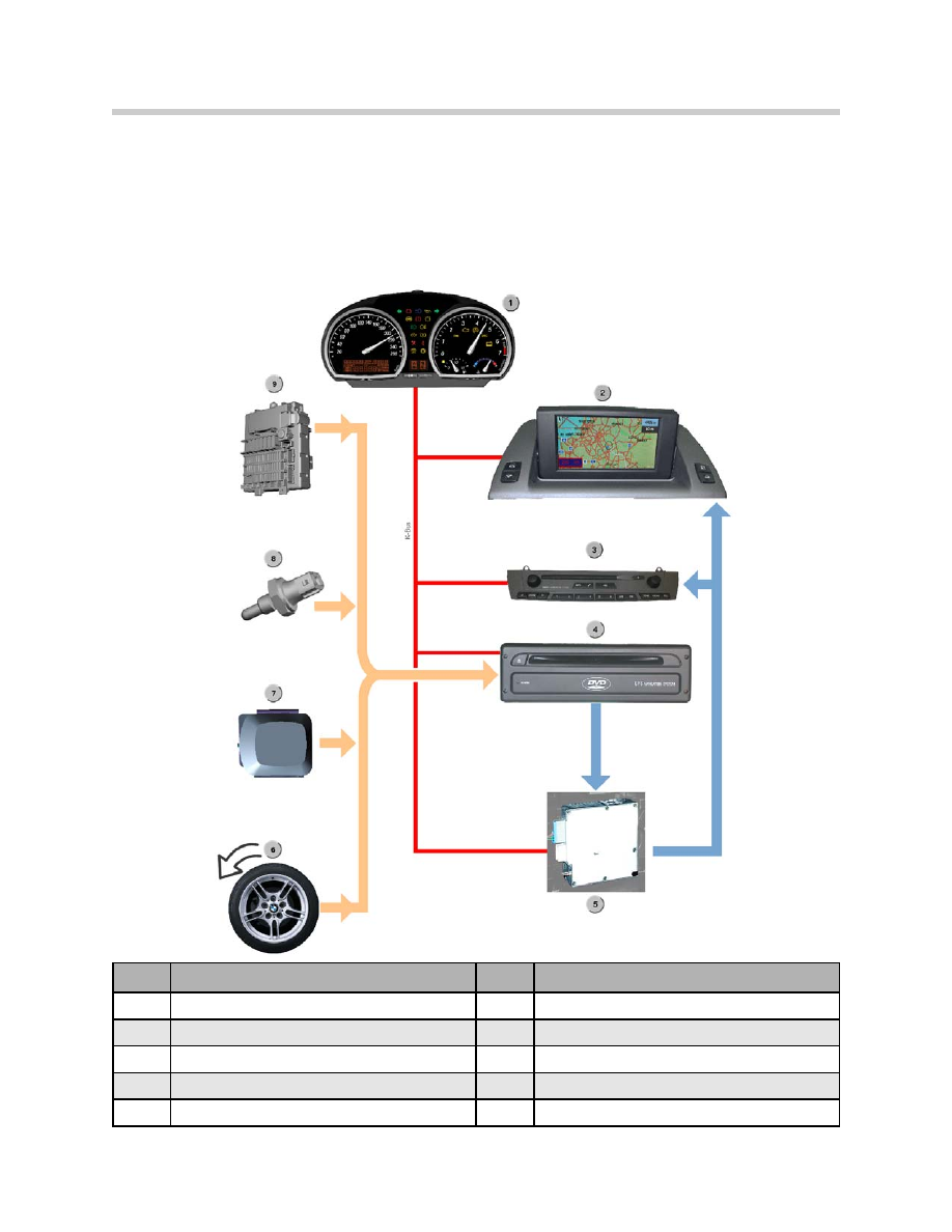
E85 Information and Communication Systems
Index
Explanation
Index
Explanation
1
Instrument Cluster
6
Wheel Speed Signal
2
Central Information Display (CID)
7
GPS Aerial
3
CID Control Panel (radio)
8
Reverse Light Switch
4
Navigation Computer (DVD)
9
Fuse box
5
Video Module

The navigation system of the E85 is based on the familiar MK-3 navigation system. The
navigation computer has been further developed and optimized for the E85 and is now
known as navigation computer DVD.
The specific features of the new system include:
• DVD drive
• Faster processor
• Larger memory
Advantages of New System
• Map presentation for navigation in the Z4 roadster
• The use of the DVD drive now facilitates presentation of all of the USA on one DVD
• Extended destination entry functions
• More accurate calculation of arrival time
• Improved route planning
• More exact traffic control management
• New display presentation
• Data on CD or DVD
Components of System
The High navigation system consists of following components:
• Central information display CID
• CID control panel
• Navigation computer DVD
• GPS aerial
• Wheel speed sensor
• Reversing light switch
• Video module
28
E85 Information and Communication Systems
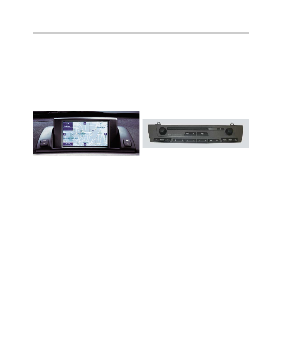
Central Information Display
The central information display is the display unit for the High navigation system. The dis-
play is designed as a 6.5" advanced TFT display for presenting the operating interface
and maps.
To optimize the legibility, the display can be precision adjusted by means of a switch.
The central information display is located in the center of the instrument panel above the
ventilation outlet.
CID Control Panel
The central information display is located in the center of the instrument panel below the
ventilation outlet.
The functions presented in the CID can be controlled with the rotary push-button on the
right and the menu key on the CID control panel.
Navigation Computer DVD
The navigation computer is located in the lockable compartment between the seats in
the partition between the vehicle interior and luggage compartment. The navigation
computer DVD incorporates the main functions for the navigation system and contains
the following components:
• DVD drive for reading information of the digitized road maps on DVD or CD
• GPS receiver for determining position before start of journey
• Yaw rate sensor for calculating position while driving
• Powerful processor for fast calculation of data
• Memory modules for buffering data
• Interfaces for communication with other systems and evaluating sensor data
• Interfaces for outputting image data and voice information
• GPS aerial
29
E85 Information and Communication Systems

GPS Aerial
The GPS aerial receives the signals from GPS satellites and transfers the data (degrees
longitude, degrees latitude, Greenwich meantime (GMT)) to the GPS receiver in the navi-
gation computer DVD for the purpose of calculating the position. This is of particular
importance during initial or re-initialization of the system. These data are also read in dur-
ing the restart procedure.
The GPS aerial is located in the middle of the roof frame behind the interior lamp.
Wheel Speed Sensor
The wheel speed sensor determines the rotary motion of the wheel. The information is
routed to the ABS/DSC control unit and the corresponding distance calculated. The
conditioned signal is then made available to the navigation computer. The ABS sensor at
the rear left is used for the purpose of determining the speed signal.
Reverse Light Switch
With the aid of the reverse light switch, the navigation system detects whether reverse
gear is engaged. On manual transmission vehicles, the reverse light switch is located in
the manual gearbox. On automatic vehicles, the reverse signal comes from the selector
lever switch.
30
E85 Information and Communication Systems

Principle of Operation
The navigation computer DVD represents a further-development of the MK-3 computer.
The computing capacity of the navigation computer DVD has been doubled (from previ-
ously 54 MHz to 108 MHz). Likewise, the capacity of the memory modules has been
enlarged and a new flash module integrated to allow for considerably faster flashing (from
previously 15.6 MIPS to 70.0 MIPS, million instructions per second).
The previous functions of the MK-3 computer have been fully adopted. Only the new or
modified functions are outlined in the following section.
The following functions are new:
• Additional destination inputs
• More accurate calculation of arrival time
• Improved direction
• Improved map presentation on the CID
• New map presentations
• Digitized road maps on DVD
The following new destination inputs are possible:
• Direct input of border crossing points
• Address book extended to 100 entries (20)
• Storage of last 20 destinations (10)
More accurate calculation of arrival time
The expected time of arrival is calculated more accurately by including the average vehi-
cle speed corresponding to the type of road.
For this purpose, the average speed of the last 7 minutes is stored corresponding to the
type of road (highway, major trunk road, district road). Based on the selected route, the
computer calculates the share of different types of road and the determined average
speed so it can calculate the arrival time more accurately.
Improved Direction
When changing from one highway to another, the number of the new roadway is
announced (voice information).
Improved Map Presentation on the CID
In future, the maps will be presented in up to 256 colors. The indicator for the current
position has been enlarged.
31
E85 Information and Communication Systems

New Map Presentations
The scaling of the maps has been extended to 1000 miles. The scales 200 miles, 500
miles and 1000 miles have been additionally introduced. As a result, all the USA can be
shown on the display. The selected route is highlighted in white.
In addition, 3 maps can be shown in different scales.
The following scales can be presented:
• The scale bar on the display corresponds to 1000 miles
• The scale bar on the display corresponds to 500 miles
• The scale bar on the display corresponds to 200 miles
The 200 miles, 500 miles and 1000 miles scales can only be presented in connection
with DVD maps. The previous CD maps only provide scales of up to 100 miles.
The map scales are selected in the "Settings" menu under "Announcement."
Digitized Maps on DVD
The navigation computer DVD is equipped with a DVD drive. The navigation computer
DVD is retro-compatible and can be used in all MK-x systems. It can also read the
previously used CDs.
Operation
The High navigation system is controlled by selecting the "GPS navigation" menu in the
main menu of the central information display.
Basic settings are possible under the menu item “Settings” in the main menu to adapt
the display to country specific requirements. The various settings can be carried out in
the windows. The red markings correspond to the current settings.
With the “Screen” menu item in the Settings menu it is possible to switch between full
and split screen.
As a result, it is possible to show the map and the navigation arrow simultaneously.
Navigation is represented with arrows while in split screen or using the OBC functions.
The mask for entering the destination is accessed after selecting the "GPS navigation"
menu. A submenu is selected by pressing the rotary push-button on the CID control
panel.
In the "Announcement" menu, the last voice announcement is repeated by pressing the
button. By pressing the button for longer than 2 seconds, the announcement is deacti-
vated or activated depending on the setting.
32
E85 Information and Communication Systems

"Route Selection" Menu
Destination Input
By pressing the button, current directions are ended in the "Destination input" menu and
the input mask is selected in order to enter a new destination.
New Route
It is possible to switch between map presentation mode and arrow presentation mode in
the "Route map" menu.
Service Information
Conversion
The navigation computer DVD is retro-compatible for all MK-x systems. The following
point must be observed when the navigation computer DVD is fitted in a vehicle with
MK-1 system:
The GPS receiver must be disconnected as the navigation computer DVD features an
integrated GPS receiver.
Diagnosis
Diagnosis of the navigation systems comprises the following features:
• Read identification
• Diagnosis enquiry, e.g. gyro value, wheel speed, eject button
Coding
Coding of the navigation systems comprises the following functions:
• Recoding a control unit
• Retrofitting a control unit
Car & key memory
No functions are available for the car & key memory.
33
E85 Information and Communication Systems

Service Mode
Service mode in the High navigation system supplies information for system diagnosis.
Accessing Service Mode
The test functions can be selected via the "Settings" menu in the central information
display. Proceed as follows:
• Terminal R active
• Select main menu
• Select "Settings" menu
• Press and hold rotary push-button for 8 seconds
• Select the required menu item from the list that now appears
• Confirm selected menu item with the rotary push-button
Switch off terminal R to end the test functions.
34
E85 Information and Communication Systems

Service Mode Menu Chart
35
E85 Information and Communication Systems
Menu
Submenu
Display
CID
SW-Status
03
HW-Status 02
Diag-Index 03
Bus-Index 01
Coding Index 01
Supplier
17
GPS
Version
Status
Tracking Info
Receiver
8.6
SW Date dd.mm.yy
Latitude Degrees/Min/Sec
Longitude Degrees/Min/Sec
Altitude Meters
Date dd.mm.yy
Time Hour:Min
G Speed Meter/Sec
Heading Degrees
Rec-Start
POS
Pos-Src
PDOP 1.8
HDOP 1.4
VDOP 2.2
CH 1
PRN 07
S/N 5.1
Visible Sat
08
Almanac Yes
Video Module
SW-Status 11
HW-Status 04
Diag-Index 02
Bus-Index 11
Coding Index 02
Supplier
09
Sensor Check
Wheel 835 RL Navi
835 RR Navi
Satellites 05
GPS Status Position Known
Gyro 2500
DIR Forward/Reverse
Telematics
VIN Last 7
Vehicle Type E85 Roadster
Color
Registration Number
SMS Code Number
D1
BMW Information ON/OFF
Auto Emergency Call ON/OFF
Initialization ON/OFF
Sign-off
ON/OFF

Service Mode Menu Chart
36
E85 Information and Communication Systems
Menu
Display
Explanation
GPS/Status
GPS/Tracking Info
G Speed
Heading
Rec-Start
Pos-Src
PDOP
HDOP
VDOP
CH
PRN
S/N
Visible Sat
Almanac
Relative Vehicle Speed over the ground
Direction of Travel
Search/Track/Position Receiver Status
Number of Satellites available for analysis
Accuracy of calculated position
< 8 Sufficient determination of position
< 4 Very goo determination of position
Channel
Satellite Detection
Better Reception = Higher Value
The number of visible satellites, signals receivable
depends on time of day and constellation
Satellite Database, automatically loaded after
15 minutes.
Sensor Check
Wheel
Satellites
GPS Status
Gyro
Direction
ABS Sensors, pulses/minute, neg. when reversing
Number of satellites currently received
07: 3 Satellites received, position possible
11: 2D Position Determined
12: 3D Position Determined
+,-, 400: mV setpoint value, halted or driving straight
ahead, >right-hand, <left-hand curve
Reverse Signal Detection
Telematics
VIN
Color
D1
BMW Information
Auto emergency Call
Initialization
Sign-Off
Vehicle Identification Number
Color Code
Telephone network/contact number
Customer Specific Information
Status ON/OFF
Telematics service status ON/OFF
Log out of telematics service

Workshop Exercise - Diagnosis
Using an instructor designated vehicle perform a complete short test. Proceed with
diagnosing the complaint as directed by the instructor. Complete the worksheet
using the proper “Complaint, Cause and Correction” format.
Vehicle:
Chassis #:
Production Date:
Complaint:
Cause:
Correction:
37
E85 Information and Communication Systems

Workshop Exercise - Diagnosis
Using an instructor designated vehicle perform a complete short test. Proceed with
diagnosing the complaint as directed by the instructor. Complete the worksheet
using the proper “Complaint, Cause and Correction” format.
Vehicle:
Chassis #:
Production Date:
Complaint:
Cause:
Correction:
38
E85 Information and Communication Systems

39
E85 Information and Communication Systems
Workshop Exercise - Diagnosis
Using an instructor designated vehicle perform a complete short test. Proceed with
diagnosing the complaint as directed by the instructor. Complete the worksheet
using the proper “Complaint, Cause and Correction” format.
Vehicle:
Chassis #:
Production Date:
Complaint:
Cause:
Correction:

Classroom Exercise - Review Questions
1.
What is the procedure for radio removal on vehicles equipped with the CID?
2.
In case of a malfunction what portions of the CID may be replaced separately?
3.
Where is the aerial diversity unit located?
4.
What is the location of the Top Hi-Fi amplifier?
5.
Why does the Navigation system now use a DVD player?
40
E85 Information and Communication Systems

Classroom Exercise - Review Questions
6.
What is the location of the GPS aerial?
7.
What is the additional wheel speed input used for on the navigation system?
8.
What are some advantages of the Carver speaker system?
41
E85 Information and Communication Systems
Document Outline
- Main Menu
- Introduction to Bus Systems
- Power Supply and Bus Systems
- Instrument Cluster Electronics
- Base Instrument Cluster
- Lighting Systems
- Entertainment and Communication
- Vehicle Features
- Navigation Systems
- Central Body Electronics ZKE III
- E46 Power Supply and Bus Systems
- E46 Driver Information Systems
- E46 Lighting Systems
- E46 Entertainment Systems
- E46 Central Body Electronics
- E85 Power Supply and Bus Systems
- E85 Driver Information
- E85 Central Body Electronics
- E85 Info and Communication Systems
- E83 Electronic Systems
- Glossary
Wyszukiwarka
Podobne podstrony:
Communication system Post and telephoning (132)
Communication system Radio and TV (134)
17 E85 Heating and Air Conditioning System
04a E85 Power Supply and Bus Systems
Communication system Post and telephoning (tłumaczenie)
Communication system Radio and TV (tłumaczenie)
4 Fuel and Lubrication System
JOINT CAPABILITIES INTEGRATION AND DEVELOPMENT SYSTEM
M37a2 Heating and Ventilation System 18 32
Multiplex Communication System
67 Audio and Visual System
Navigation and Audio System
Audel Hvac Fundamentals, Air Conditioning, Heat Pumps And Distribution Systems (Malestrom)
Lynge Odeon A Design Tool For Auditorium Acoustics, Noise Control And Loudspeaker Systems
Introduction to Mechatronics and Measurement Systems
M37a1 Heating and Ventilation System 1 17
LINGUISTIC COMPETENCE AND COMMUNICATIVE
Brain Facts A Primer on the Brain and Nervous System The Society for Neuroscience
COMMUNICATION SYSTEM
więcej podobnych podstron