
Dirt
Jumper
1
QR20
INSTRUCTIONS
GENERAL RULES
1. Where specified, assemble and disas-
semble the shock absorption system us-
ing the M
ARZOCCHI
special tools only.
2. On reassembling the suspension system,
always use new seals.
3. Clean all metal parts with a special,
preferably biodegradable solvent, such
as trichloroethane or trichloroethylene.
4. Before reassembling, lubricate all parts
in contact with each other using silicone
fat spray or a specific oil for seals.
5. Always grease the lip seal rings before
reassembling.
6. Use wrenches with metric size only.
Wrenches with inch size might damage
the fastening devices even when their
size is similar to that of the wrenches in
metric size.

Dirt
Jumper
1
QR20
FAILURES, CAUSES AND REMEDIES
This paragraph reports some failures that may occur when using the fork. It also indicates possible causes and suggests a remedy. Always
refer to this table before doing any repair work.
Adjuster position does not affect fork opera-
tion
1. Dirt inside legs
2. O-ring into pumping element damaged.
1. Clean carefully and change oil
2. Replace O-ring.
Excessive play of stanchions in the sliders
Pilot bushings are worn
Replace pilot bushings
Fork has not been used for some time
and is locked out
Oil seals and dust seals tend to stick to
stanchions
Raise dust seal and lubricate stanchion
tube, dust seal and oil seal
Oil leaking through the bottom of slider
O-rings at pumping element bottom and
adjusting rod damaged.
Replace the O-rings
Oil leaking though the top of slider
1. Oil seal is worn out
2. Stanchion tube is scored
3. Excessive dirt on oil seal
1. Replace oil seal
2. Replace crown/stanchions assembly, oil
seals and dust seals
3. Clean the oil seal seat and replace oil seal
FAILURES
CAUSES
REMEDIES

Dirt
Jumper
1
QR20
RECOMMENDATIONS FOR
MAINTENANCE
M
ARZOCCHI
forks are based on advanced
technology, supported by year-long experi-
ence in the field of professional mountain
biking. In order to achieve best results, we
recommend to check and clean the area
below the dust seal and the stanchion tube
after each use and lubricate with silicone
oil.
In general, M
ARZOCCHI
forks can offer top
performance from the start. However, in
some cases a short running-in period is
required (5-10 hours) for inner adjustments.
This running-in period will make fork life
longer and ensure fork top performance
over time.
IMPORTANT: change oil at least every
100 working hours.
Polished forks should be cleaned with
bodywork polish at regular intervals in
order to preserve their original finish.
Dirt
Jumper
1
QR20
Nm
6
B
D
B
C
A
A
C
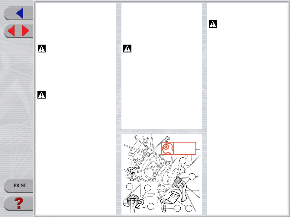
DISC BRAKE SYSTEM ASSEMBLY
WARNING: If a disc brake system
is installed, it is absolutely forbidden
to loosen and remove original brake sup-
ports fixing pins. In fact, apart from retain-
ing Cantilever or V-brake levers, they also
play an important role in securing slider
bottom to slider-arch monolith. If needed,
replace these pins with screws (part no.
532979QF) available as spare parts.
Tighten the above screws to 10 Nm.
IMPORTANT: screw and pin threading is
treated to ensure hydraulic seal. Never
reuse screws and pins which have been
removed.
Assembling the brake caliper onto the slider
is a very delicate operation that should be
carried out with extreme care.
Improper assembly might overstress the
caliper supports which might break.
When installing the disc brake system, be
sure to properly follow the instructions given
by the manufacturer.
INSTALLATION
Installing the fork on a bicycle is a very
delicate operation that should be carried
out with extreme care. The installation should
always be checked by one of our Technical
Service Centers.
WARNING: Steer tube/headset
mounting and adjustment must be
carried out in compliance with the headset
manufacturer’s instructions. Improper in-
stallation may jeopardize the safety of the
rider.
To replace it, contact one of our Technical
Service Centers with the required tools.
WARNING: In case of improper
installation of the steer tube into the
crown, the rider might lose control of his/
her bicycle, thus jeopardizing his/her safety.
FRONT WHEEL ASSEMBLY
IMPORTANT: fixing the front wheel prop-
erly as specified in the instructions given
below is essential for the proper operation
of this fork and all related devices, and
therefore for safe riding. You are advised to
follow these instructions closely.
Slacken the lock nut of the quick release
lever so the hub will fit between the fork
sliders.
Make sure the quick release bushings (A)
are centered to the recesses in the sliders.
Lock the quick release lever (B) and make
sure the bushings (A) are properly seated
in the sliders.
Fit bolt end (C) in suitable slider groove and
tighten the screw (D) to specified torque.
WARNING: These sliders are spe-
cifically designed to fit this type of
hub. Do not use any hub design other than
that specified here, as this would not ensure
proper fastening of the wheel and may lead
to breakdown of the assembly components.
Dirt
Jumper
1
QR20
2
C
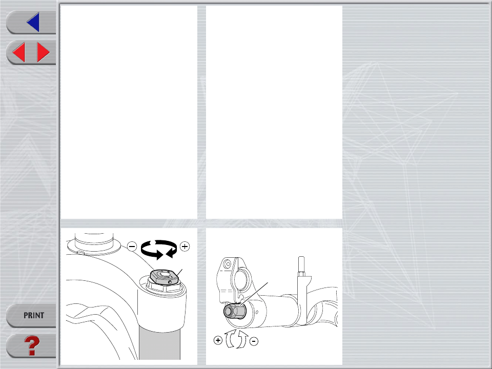
ADJUSTMENT
SPRING PRELOAD
Spring preload determines COMPRESSION
damping and is adjusted by turning the
adjustment knob (2) on the top of the fork
legs. From the factory the fork is set at
minimum preload, i.e. the adjustment knob
completely unscrewed counterclockwise.
However, springs are slightly preloaded to
counteract static loads. By turning the ad-
justment knob clockwise, the preload is
increased up to the maximum value equal
to 15 mm spring preload. This adjustment is
essential in order to have the right fork
response for the rider’s weight and riding
style.
REBOUND ADJUSTMENT
(only right leg)
Each fork leg is equipped with an adjuster
screw (C) for REBOUND damping at slider
bottom.
To adjust, always start from the minimum
damping setting, i.e. with the screw fully
turned counterclockwise. Each adjusting
position can be identified by a click.
IMPORTANT: do not force the adjuster
knob (C) over its limit.
Dirt
Jumper
1
QR20
▲
▲
▲
▲
▲
▲
▲
▲
▲
▲
▲
▲
▲
▲
▲
▲
▲
▲
▲
▲
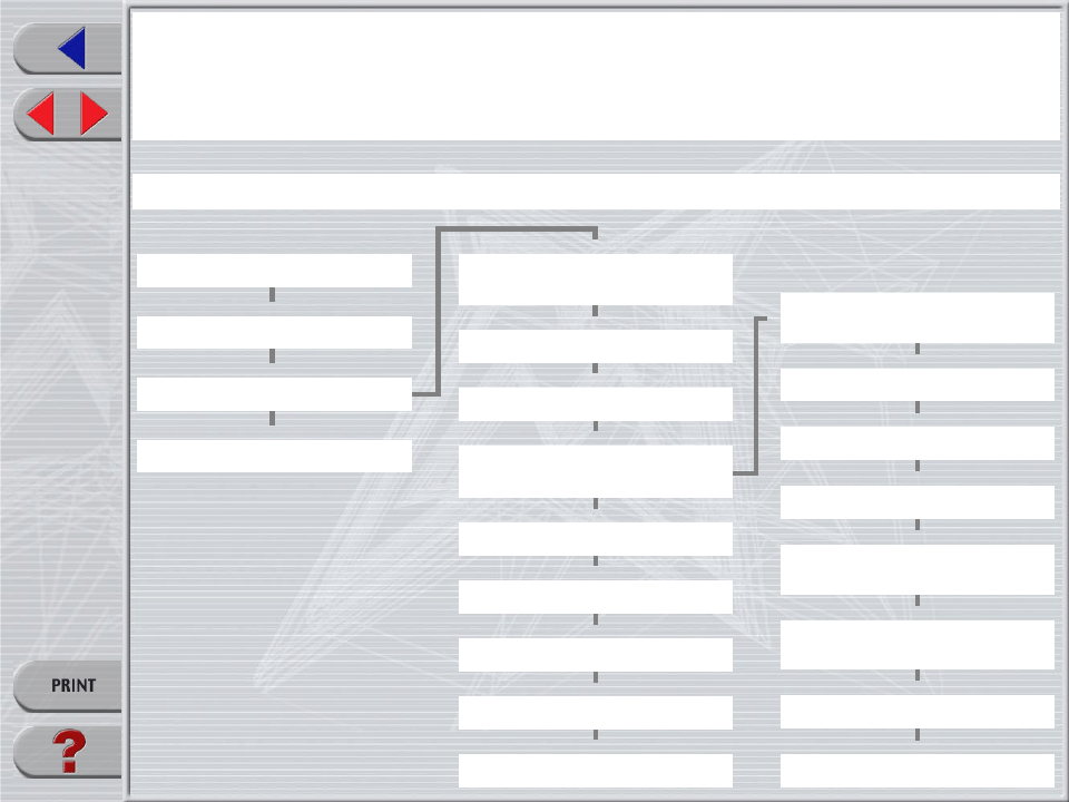
DISASSEMBLY
GENERAL
– The reference numbers given in this section relate to the components shown in the fork exploded view.
– Before starting any operation. please read the diagram below. It shows the quickest procedure and the exact disassembling sequence.
Locate the part you need to remove in the diagram, then look at the arrows to determine which other parts you need to remove first.
DISASSEMBLY DIAGRAM
FORK LEG OIL CHANGE
CHANGING PUMPING
ELEMENT SEALS
FOOT NUT FIG. 4
SPRING FIG. 2
DUST SEAL FIG. 6
STOP RING. 7
OIL SEAL FIG. 8
PUMPING ROD FIG. 12
REBOUND SPRING FIG. 12
VALVE ASSEMBLY
CHANGE
PILOT BUSHING AND
SEAL ASSEMBLY CHANGE
STANCHION TUBE CAP FIG. 1
FOOT BUFFER FIG. 11
CROWN AND STANCHIONS
ASSEMBLY FIG. 5
SPRING CHANGE
BOTTOM ADJUSTER FIG. 3
PUMPING ELEMENT INNER O-RING
FIG. 13
STOP RING FIG. 14
UPPER WASHER FIG. 9
PILOT BUSHING FIG. 10
VALVE ASSEMBLY FIG. 14
Dirt
Jumper
1
QR20
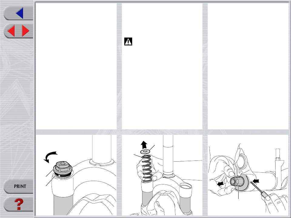
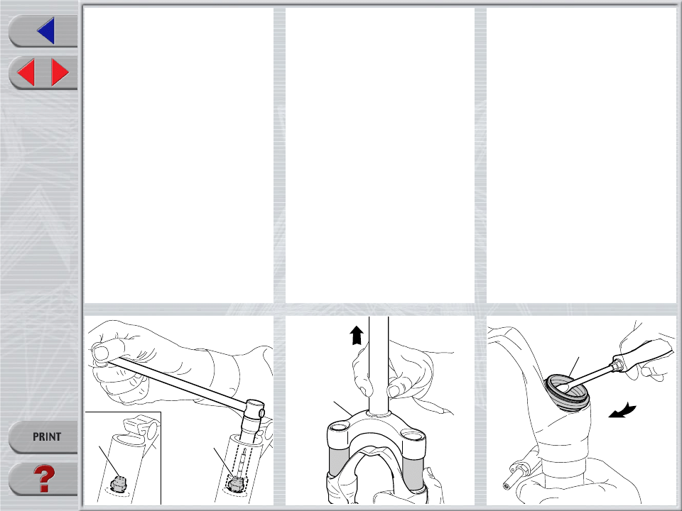
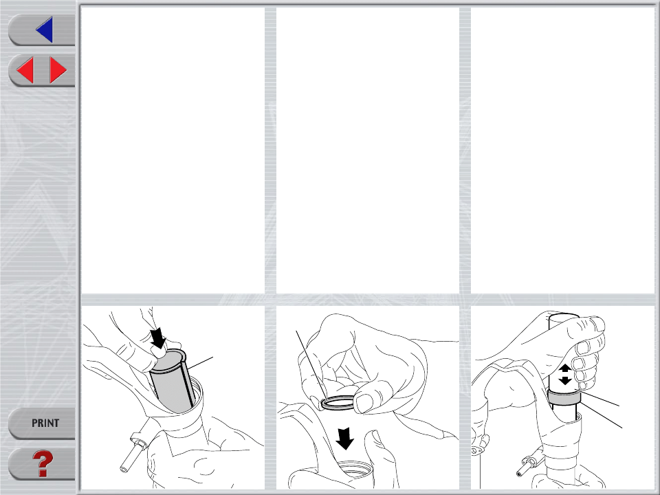
SPRING CHANGE
FIG. 1
Unscrew the caps (5) with a 21 mm socket
wrench.
Remove the caps complete with O-ring (6)
from the stanchions.
FIG. 2
Push the stanchions into the sliders and
remove the lower washer (11) and the
spring (34) from each fork leg.
Drain all oil from the fork legs.
WARNING: Remember to always
recycle any used oil.
To change the fork leg oil follow the proce-
dure as described in section “REASSEM-
BLY” from Fig. 27 to Fig. 29.
PILOT BUSHING AND SEAL
ASSEMBLY CHANGE
FIG. 3 (only right leg)
Turn fork legs upside down and press
adjuster retainer (28) with a small screw-
driver to release it.
Remove adjuster assembly (28) from the
slider.
5
6
28
34
11
Dirt
Jumper
1
QR20
26
29
Dx.
Sx.
1
FIG. 4
Remove foot nuts (26) and (29) with a
socket wrench.
FIG. 5
Withdraw the crown and stanchions as-
sembly (1) from the sliders.
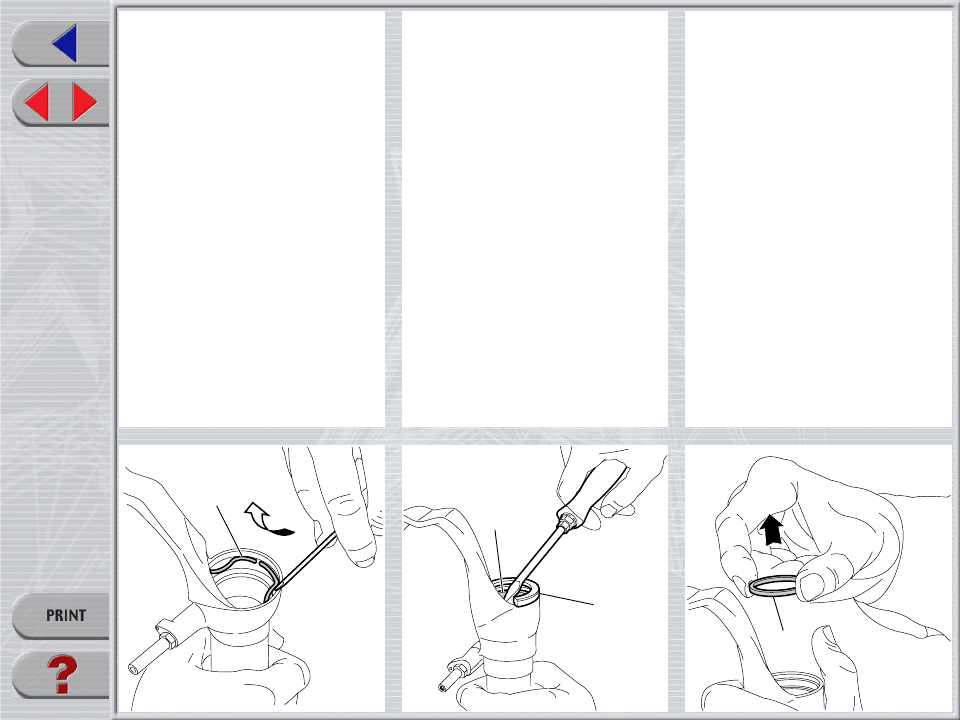
FIG. 6
Remove the dust seal (19) from the top of
the sliders using a small screwdriver.
19
Dirt
Jumper
1
QR20
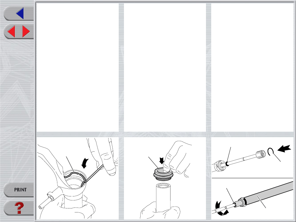
FIG. 7
Remove the stop ring (20) from the sliders
by placing the screwdriver bit in one of the
three openings on the stop ring.
IMPORTANT: when removing the stop
ring, make sure not to damage its seat.
FIG. 8
Fit the slider protector (A) onto the slider
and remove the oil seal (21) with the help
of a large screwdriver.
IMPORTANT: when removing the oil seal,
make sure not to damage its seat. Once
removed the oil seals should not be used
again.
FIG. 9
Remove the upper washer (22) from the
slider.
20
21
A
22
Dirt
Jumper
1
QR20
23
18
25
14
42
25
12
Sx.
Dx.
13
15
14
12
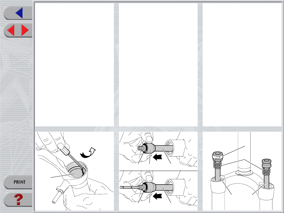
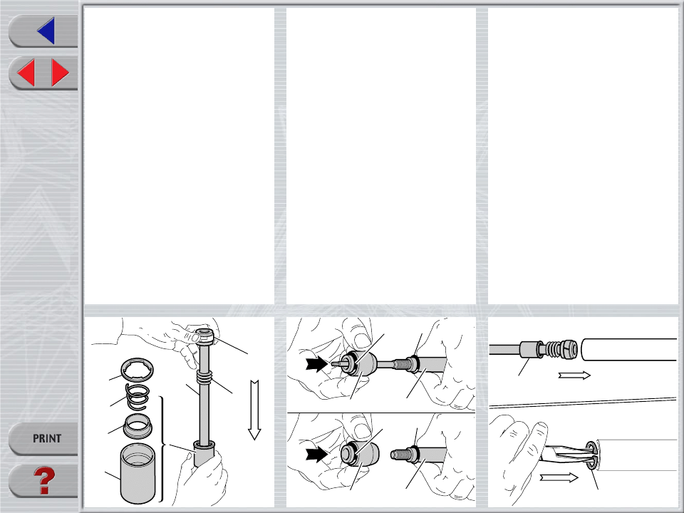
FIG. 10
Fit the bit of a small screwdriver into upper
edge slot of the pilot bushing (23) and lift
gently. Pull the bushing out of the slider and
make all necessary changes.
REPLACING PUMPING ELEMENT
SEALS
FIG. 11
Remove the foot buffer (18) and (42)
complete with ring (25) from the pumping
rod ends (14) and (12).
FIG. 12
Withdraw the pumping elements (14) and
(12) and the rebound spring (15) from the
stanchion tube top.
Replace the seal ring (13) if damaged or
worn out.
Dirt
Jumper
1
QR20
27
14
A
33
17
40
39
35
16
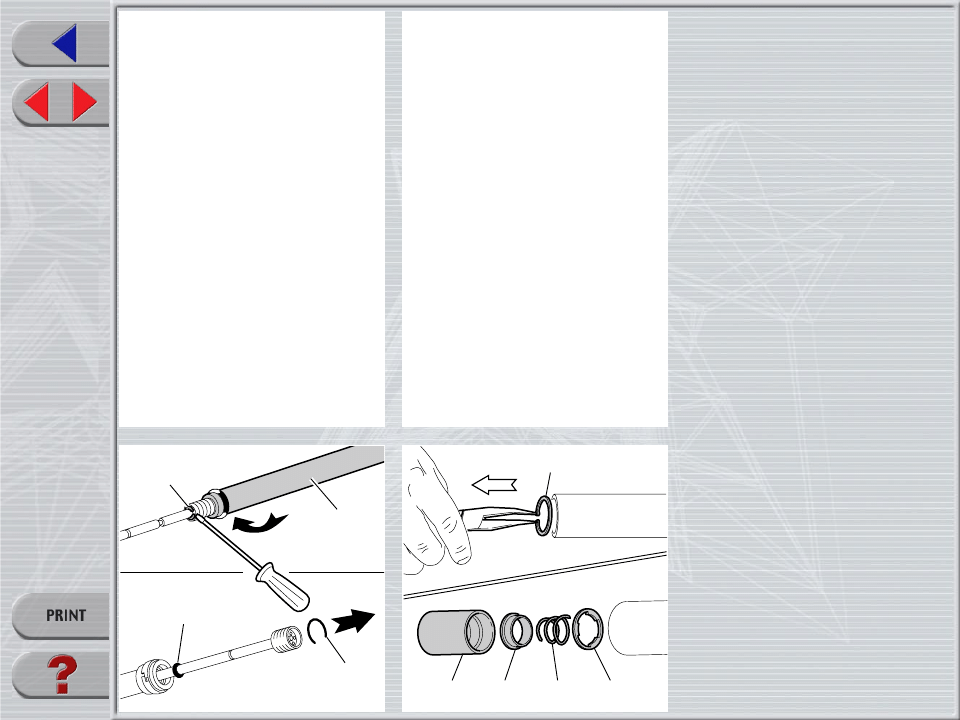
FIG. 13 (only right leg)
Remove the stop ring (33) from pumping
element bottom (14) with a small flat screw-
driver.
Mark stop ring seat into inner rod for proper
fitting.
Use the same screwdriver to remove the
ring (A) and screw inner rod until adjuster
threaded end is disengaged from pumping
element.
Remove inner rod and replace O-ring (27)
if damaged.
VALVE ASSEMBLY CHANGE
(only right leg)
FIG. 14
To check that the valve assembly is operat-
ing correctly, it is necessary to work on the
inside of the stanchion tube.
Slip off the stop ring (17) using pointed
pliers.
Pull the valve assembly out of the stanchion
with one finger in the following order:
pocket (40), valve (39) rebound spring
(35) and washer (16).
Dirt
Jumper
1
QR20
23
22
21
B
REASSEMBLY
CAUTION: before reassembling, all metal
components should be washed carefully
with inflammable, preferably biodegrad-
able, solvent and dried with compressed
air.
PILOT BUSHING AND SEAL
ASSEMBLY
FIG. 15
Check that no dirt or debris is between
slider and bushing. Insert the pilot bushing
(23) into place so that it adheres to the
slider.
FIG. 16
Fit the upper washer (22) into the slider so
that it touches the pilot bushing.
FIG. 17
Lubricate the oil seal (21) and place it onto
the seal press (B) with the hollow side
toward the slider.
Press the oil seal until it touches the lower
washer by using the above seal press.
Dirt
Jumper
1
QR20
20
19
33
14
A
27
FIG. 18
Insert the stop ring (20) into the slider
making sure it is properly seated into place.
Use buffer (B) to properly seat the ring into
the slider.
FIG. 19
Lubricate the dust seals (19) and fit them
into the stanchions from the spring end.
PUMPING ROD ASSEMBLY
FIG. 20 (only right leg)
Lubricate the O-ring (27) and fit inner rod
threaded end into pumping element (14).
Turn inner rod clockwise so that threaded
end can be seen the into pumping element
and stop ring seat (33), marked during
disassembly.
Fit stop ring (33) into inner rod seat.
Dirt
Jumper
1
QR20
40
39
35
16
14
15
13
25
18
14
24
25
42
12
24
Dx.
Sx.
17
F
Dx.
VALVE AND PUMPING ROD
ASSEMBLY
FIG. 21 (only right leg)
After having overhauled or replaced the
valve unit and after having cleaned the
inside of the tube, reassemble.
Assemble valve components, in correct se-
quence: washer (16), rebound spring (35),
valve (39) and pocket (40).
Then fit pumping element (14) with seal
ring (13) and rebound spring (15) into the
valve assembly.
FIG. 22
Lubricate the O-rings (24) and (25) and
reassemble the foot buffer (18) onto pump-
ing element end (14) and foot buffer (42)
on pumping element top (12).
FIG. 23 (only right leg)
Fit this assembly into the stanchion tube and
properly seat the valve assembly (F).
Insert the stop ring (17).
Dirt
Jumper
1
QR20
Sx.
12
15
1
19
19
FIG. 24 (only left leg)
Fit pumping element (12) from stanchion
top with rebound spring (15).
CROWN AND STANCHIONS
ASSEMBLY
FIG. 25
Fit the crown and stanchions assembly (1)
- with the dust seals in place - gently into the
sliders seals.
IMPORTANT: to avoid any damages to
sealing surfaces, keep the stanchions duly
lubricated and squared into the sliders.
Press the crown and stanchions assembly
fully down and check that threaded ends of
pumping elements (14) and (12) are com-
ing out through the bottom of the sliders.
Check to see that the stanchions slide unre-
stricted by cycling the fork up and down
several times.
The tube should slide freely inside the seal
assembly without any side play. In the event
it is too hard or too soft, repeat the previous
steps described above and check compo-
nents to ensure they are not damaged.
Seat the dust seals (19) on top of the
sliders.
26
29
Dx.
Sx.
Nm
11
FIG. 26
Screw the foot nuts (26) and (29) on the
threaded elements of pumping elements
(14) and (12).
Tighten to 11 Nm.
Check to verify that the stanchions slide
properly through the stroke by pumping
them up and down several times.
Dirt
Jumper
1
QR20
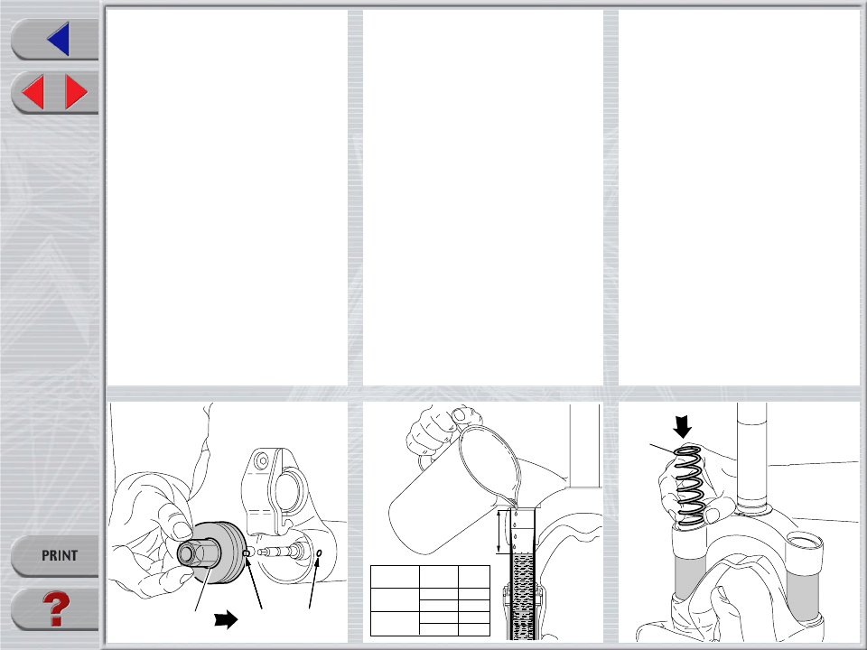
H
110
130
Lh.
Rh.
Lh.
Rh.
55
55
50
40
Travel
Leg
H
(mm)
(mm)
HOW TO FILL WITH OIL
FIG. 28
Pour oil little by little when the stanchions
are fully down and then pump with the
crown so as to have a better filling.
Check that the oil level is H mm from the top
of the stanchion tube, in both legs.
34
SPRING AND CAP
FIG. 29
Fit the springs (34) into each stanchion
tube.
28
D
E
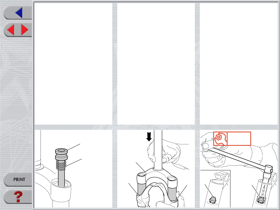
FIG. 27
Fit the retainer (D) into the slider (E) to
reassemly the adjuster unit (28).
Dirt
Jumper
1
QR20
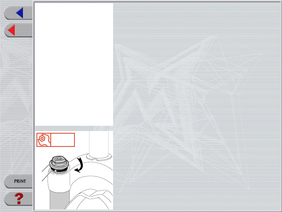
Nm
20
5
6
FIG. 30
Lubricate the O-ring (6) on the cap (5).
Turn the preload adjuster (9) counterclock-
wise until it is at its minimum setting and
install the lower washer (11).
Start the caps with the O-ring (6) in place
into the stanchion tube threads by hand.
Tighten caps (5) to 20 Nm.
Wyszukiwarka
Podobne podstrony:
2002 L Dj15 QR20 110
2002 L Z1 DO QR20 110
2002 L Super T QR20
2002 L Z1 FR 110
2002 L Z1 DO 110
2002 L jrT QR20 170
ĐHĐL Giáo Trình Hợp Ngữ (NXB Đà Lạt 2002) Nguyễn Hữu Lộc, 110 Trang
2002 L Z1 FR QR20 130
Ustawa z 30 10 2002 r o ubezp społ z tyt wyp przy pracy i chor zawod
ecdl 2002
ei 03 2002 s 62
więcej podobnych podstron