Super T
QR20
GENERAL RULES
1. Where specified, assemble and disas-
semble the shock absorption system us-
ing the M
ARZOCCHI
special tools only.
2. On reassembling the suspension system,
always use new seals.
3. If two screws are close one to the other,
always tighten using a 1-2-1 sequence.
In short, screw the first screw just up to the
point it is well tightened, then tighten the
second screw and then go back to the
first one and screw it tighter.
4. Clean all metal parts with a special,
preferably biodegradable solvent, such
as trichloroethane or trichloroethylene.
5. Before reassembling, lubricate all parts
in contact with each other using silicone
fat spray.
6. Always grease the conic seal rings be-
fore reassembling.
7. Use wrenches with metric size only.
Wrenches with inch size might damage
the fastening devices even when their
size is similar to that of the wrenches in
metric size.
INSTRUCTIONS

Super T
QR20
FAILURES, CAUSES AND REMEDIES
This paragraph reports some troubles that may occur when using the fork. It also indicates possible causes and suggests a remedy. Always
refer to this table before doing any repair work.
Oil leaking through the bottom of slider
O-ring seal on the cartridge nut is damaged
Replace the O-ring seal
Excessive oil build up on stanchions
1. Oil seal is worn out
2. Stanchion tube is scored
3. Excessive dirt on slider oil seal
1. Replace oil seal
2. Replace stanchion tube, oil seal and dust
seal
3. Clean the oil seal seat and replace oil
seal
Fork has not been used for some time and
is locked out
Oil seals and dust seals tend to stick to
stanchion tube
Raise dust seal and lubricate stanchion
tube, oil seal and dust seal
Fork rebounds too fast even though the
adjuster is set to hardest damping position
Cartridge is faulty
Replace hydraulic cartridge
Excessive play of stanchions into the sliders
Main slider bushings are worn
Replace main slider bushings
FAILURES
CAUSES
REMEDIES
Adjuster position does not affect fork opera-
tion
Dirt inside legs
Clean carefully and change oil
Super T
QR20
INSTALLATION
Installing the fork on a bicycle is a very
delicate operation that should be carried
out with extreme care. The installation should
always be checked by one of our Technical
Service Centers.
WARNING: Steer tube/headset
mounting and adjustment must be
carried out in compliance with the headset
manufacturer’s instructions. Improper in-
stallation may jeopardize the safety of the
rider.
To replace it, contact one of our Technical
Service Centers with the required tools.
WARNING: In case of improper
installation of the steer tube into the
crown, the rider might lose control of his/
her bicycle, thus jeopardizing his/her safety.
MOUNTING THE FORK ON THE
FRAME
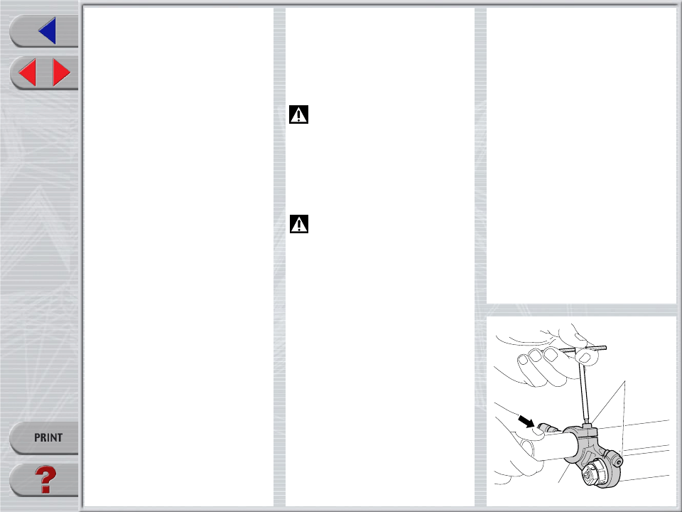
FIG. A
Remove the upper crown (1) from steer
tube and fork legs by loosening the 3
fastening bolts (11).
1
11
RECOMMENDATIONS FOR
MAINTENANCE
M
ARZOCCHI
forks are based on advanced
technology, supported by year-long experi-
ence in the field of professional mountain
biking. In order to achieve best results, we
recommend to check and clean the area
below the dust seal and the stanchion tube
after each use and lubricate with silicone
oil.
In general, M
ARZOCCHI
forks can offer top
performance from the start. However, in
some cases a short running-in period is
required (5-10 hours) for inner adjustments.
This running-in period will make fork life
longer and ensure fork top performance
over time.
IMPORTANT: change oil at least every
100 working hours.
Polished forks should be cleaned with
bodywork polish at regular intervals in
order to preserve their original finish.
Super T
QR20
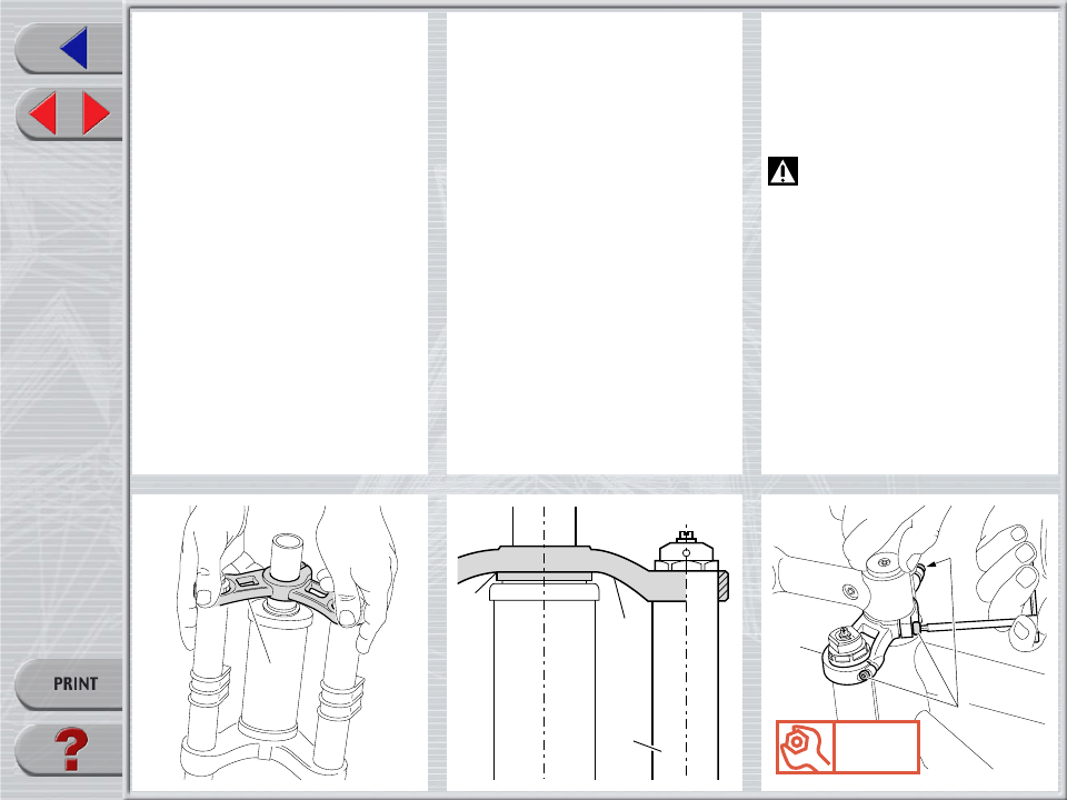
FIG. B
Assemble the fork to the frame complete
with headset. Fit the upper crown (1) into
the stanchions and the steer tube.
1
FIG. C
The stanchions edge (28) must be aligned
with or slightly lower than the upper crown
(1).
If fork legs overprotrude, fit some spacers
(C) to the plate close to the steer tube.
1
C
28
FIG. D
Fit the handlebar support and the A-Head
Set cap over the upper crown (1) and then
adjust the steering.
Now finally tighten the 3 bolts (11) on the
upper crown to 11 Nm.
WARNING: Loosen the 3 screws
(11) on the upper crown before
adjusting the steering. Tighten the above
bolts to the specified torque when finished.
11
1
Nm
11
Super T
QR20
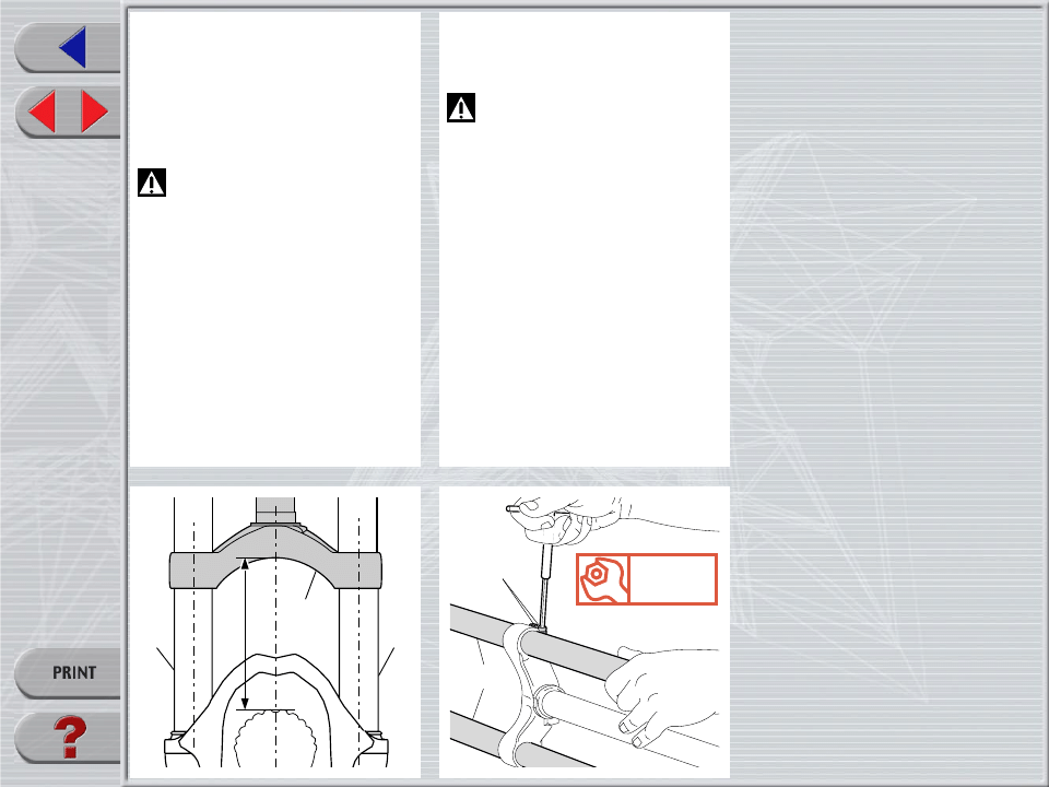
FIG. F
Tighten the 4 stanchions (28) fastening
screws (15) onto the crown to 11 Nm.
WARNING: do not overtighten the
screws holding the stanchions to the
crown as this may distort the stanchions and
weaken the whole structure.
After any installation always check for the
proper torque of screws fastening stan-
chion tube onto lower crown and on upper
crown.
15
28
Nm
11
FIG. E
If the crown (13) position with respect to
the stanchions (28) has been changed for
any reason, adjust the original distance.
– Distance “H” between crown and tyre
edge (when inflated) should not be lower
than total travel (170 mm) + 3 mm.
WARNING: if lower Crown is im-
properly matched with stanchions, it
may touch the tyre and cause severe inju-
ries to the rider.
H
28
28
13
Super T
QR20
DISC BRAKE SYSTEM ASSEMBLY
Assembling the brake caliper onto the slider
is a very delicate operation that should be
carried out with extreme care.
Improper assembly might overstress the
caliper supports which might break.
When installing the disc brake system, be
sure to properly follow the instructions given
by the manufacturer.
FRONT WHEEL ASSEMBLY
IMPORTANT: fixing the front wheel prop-
erly as specified in the instructions given
below is essential for the proper operation
of this fork and all related devices, and
therefore for safe riding. You are advised to
follow these instructions closely.
Slacken the lock nut of the quick release
lever so the hub will fit between the fork
sliders.
Make sure the quick release bushings (A)
are centered to the recesses in the sliders.
Lock the quick release lever (B) and make
sure the bushings (A) are properly seated
in the sliders.
Fit bolt end (C) in suitable slider groove and
tighten the screw (D) to specified torque.
WARNING: These sliders are spe-
cifically designed to fit this type of
hub. Do not use any hub design other than
that specified here, as this would not ensure
proper fastening of the wheel and may lead
to breakdown of the assembly components.
Nm
6
B
D
B
C
A
A
C
Super T
QR20
ADJUSTMENTS
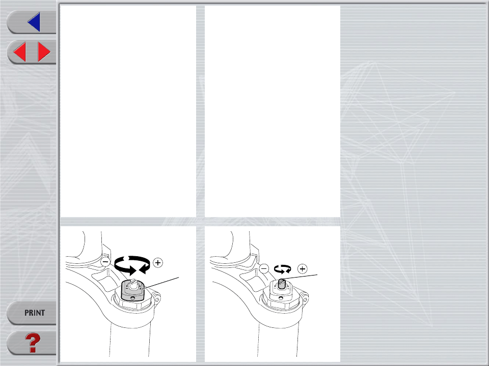
SPRING PRELOAD
The spring preload for COMPRESSION
damping can be adjusted by turning the
knob (2) on top of fork legs. From the
factory the From the factory the fork is set at
minimum preload, i.e. the adjustment knob
completely unscrewed counterclockwise.
However, the springs are slightly preload-
ed to help counteract static loads. By turn-
ing the adjustment knob clockwise, the
preload is increased up to the maximum
value equal to 15 mm of spring preload.
This adjustment is essential in order to have
the right fork response for the rider’s weight
and riding style.
REBOUND DAMPING ADJUSTMENT
The fork legs feature an adjuster (C) for
REBOUND damping adjustment. Turning
this adjuster clockwise into the cartridge
rod, changes the hydraulic setting of the
inner valves. In short, the amount of adjust-
ment applied on the piston in the fluid
determines the rate of compression damp-
ing.
To adjust, always start from the minimum
damping setting, i.e. unscrew completely
counterclockwise. About 8 turns - abt. 4 mm
of the adjustment - are possible.
2
C

Super T
QR20
DISASSEMBLY
GENERAL
– The reference numbers given in this section relate to the components shown in the fork exploded view.
– Operations refer to the fork legs already removed from the upper crown and from the crown.
– Before starting any operation. please read the diagram below. It shows the quickest procedure and the exact disassembling sequence.
Start from the part to be disassembled and then follow the arrows to remove the other parts.
DISASSEMBLY DIAGRAM
▲
▲
▲
▲
▲
▲
▲
▲
▲
▲
▲
▲
▲
▲
▲
STOP RING FIG. 2
STANCHION TUBE FIG. 8
DUST SEAL FIG. 9
SPRING FIG. 5
PRELOAD KNOB FIG. 1
HYDRAULIC
CARTRIDGE CHANGE
FOOT NUT FIG. 6
HYDRAULIC CARTRIDGE FIG. 7
GUIDE BUSHING AND
SEAL ASSEMBLY CHANGE
OIL SEAL FIG. 11
UPPER WASHER FIG. 12
GUIDE BUSHING FIG. 13
STANCHION TUBE CAP FIG. 3/4
SPRING CHANGE
STOP RING FIG. 10
FORK OIL CHANGE
Super T
QR20
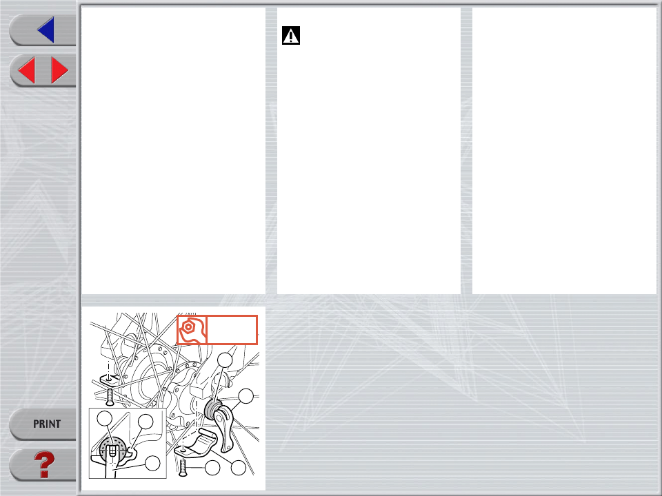
SPRING CHANGE
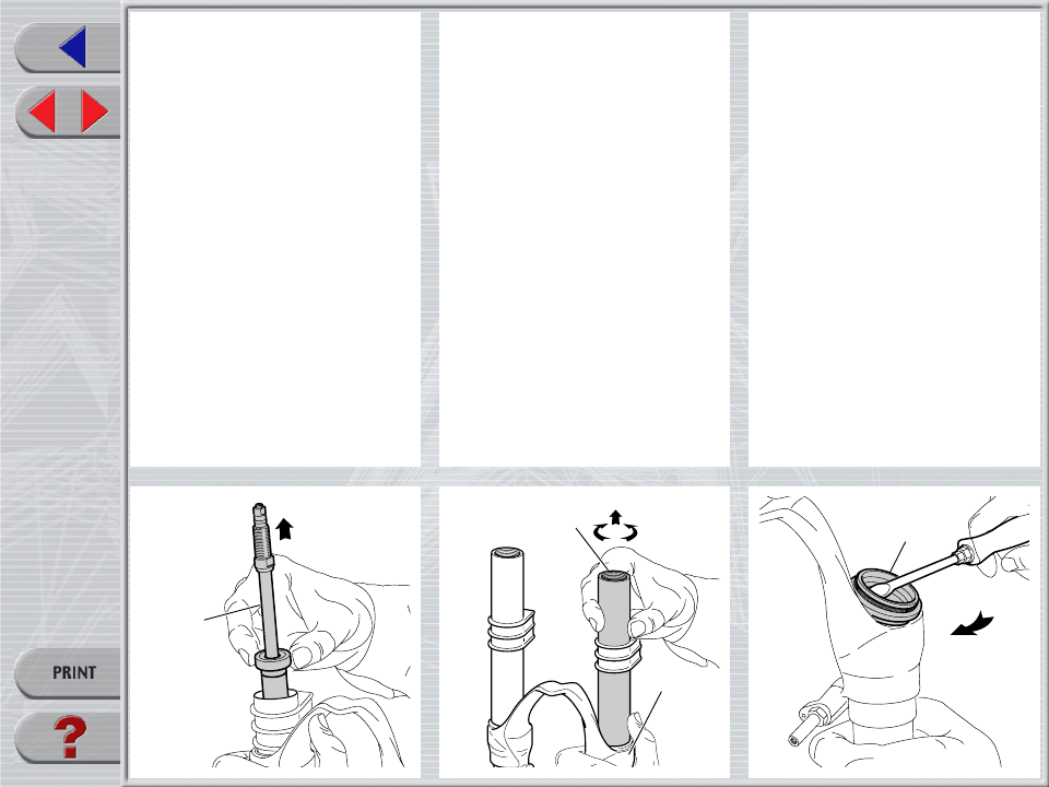
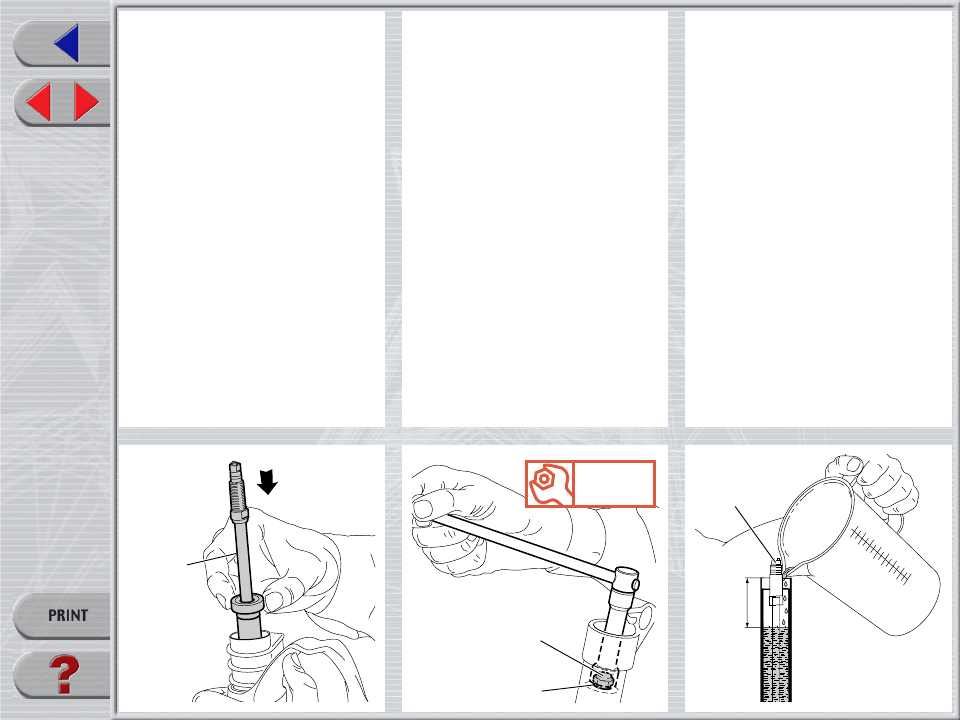
FIG. 1
Set the knob (2) to the minimum preload
position.
Loosen the grub screw (3) fastening the
preload knob (2) by means of a 1.5 mm
Allen wrench. Remove grub screw from cap
assembly.
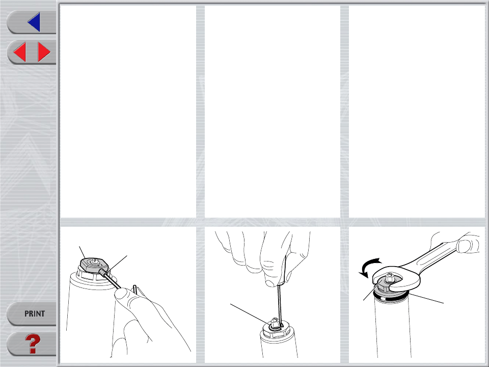
FIG. 2
Remove the stop ring (4) from the top of the
preload knob support with a small screw-
driver.
FIG. 3
Place the stanchion tube in a vice. Be sure
not to damage or squeeze stanchion in the
process. Unscrew the plugs (5) with a 26
mm hexagon wrench.
Remove the plugs complete with the
O-ring (6) from the stanchions.
2
3
4
5
6
Super T
QR20
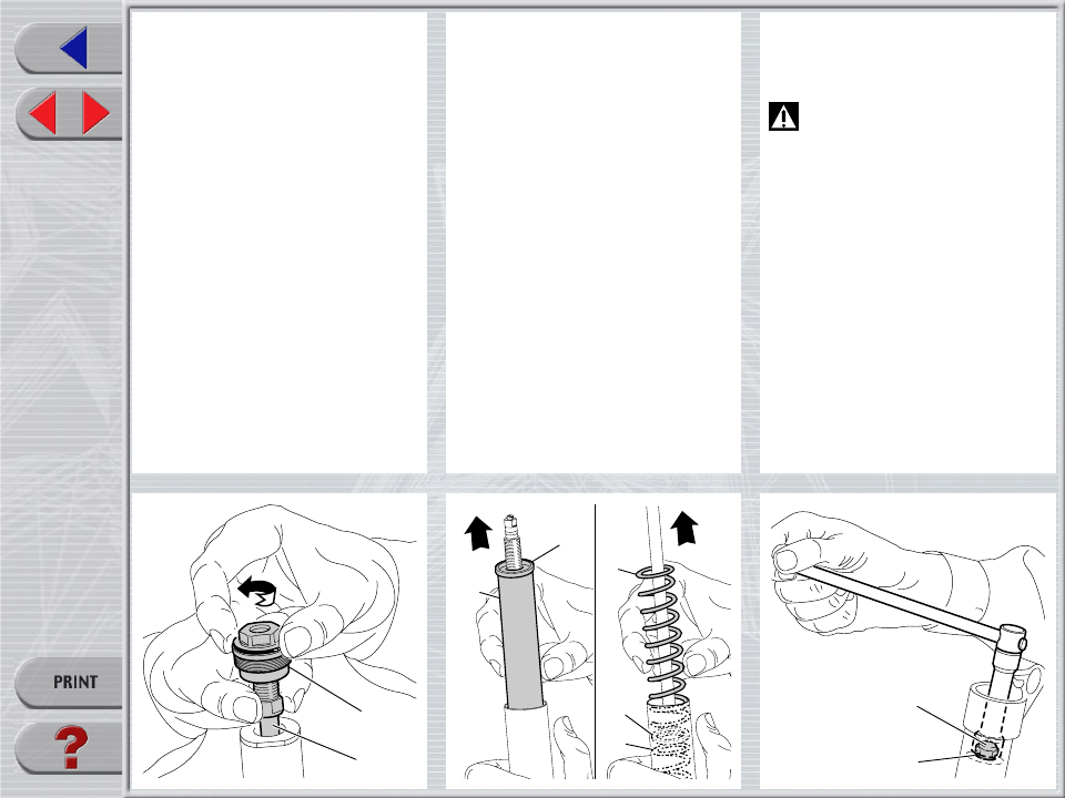
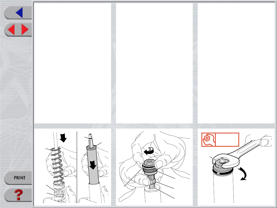
FIG. 4
Unscrew the cap (5) from the cartridge
(21) rod.
5
21
10
37
8
9
8
35
34
FIG. 5
Push the stanchion tube into the slider and
remove the top washer (8), the preload
sleeve (9), the spring (10), the second
washer (8) and the other spring (37).
Let all the oil drain into the fork leg.
By following this procedure, there is no
need to check the oil level.
Make all necessary changes.
HYDRAULIC CARTRIDGE CHANGE
FIG. 6
Let all the oil drain out.
WARNING: Remember to always
recycle any used oil.
To change the fork leg oil follow the proce-
dure as described in section “REASSEMBLY”
from FIG. 22 to FIG. 27.
Turn the fork leg upside-down and unscrew
the foot nut (35) complete with O-ring (34)
by the use of a 15 mm socket wrench.
Super T
QR20
FIG. 7
Pull the hydraulic cartridge (21) complete
with foot washer (36, see exploded view)
out of the stanchion tube.
Replace the whole hydraulic cartridge.
21
28
27
22
GUIDE BUSHING AND SEAL
ASSEMBLY CHANGE
FIG. 8
Pull the stanchion tube (28) completely out
of the slider (27).
FIG. 9
Use a small screwdriver and remove the
dust seal (22) from slider top.
Super T
QR20
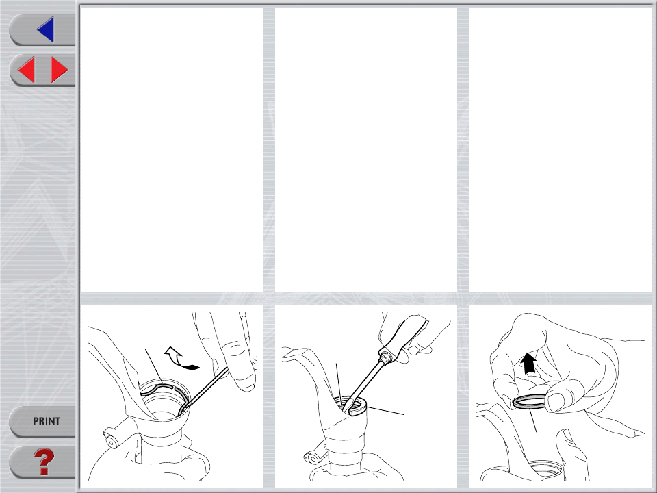
FIG. 10
Remove the stop ring (23) from the slider
by placing the screwdriver bit in one of the
three openings on the stop ring and care-
fully lifting the ring out of place.
IMPORTANT: when removing the stop
ring, make sure not to damage its seat.
FIG. 11
Fit the slider protector (A) onto the slider
and remove the oil seal (24) with the help
of a large slot screwdriver.
IMPORTANT: when removing the oil seal,
make sure not to damage its seat. Once
removed the oil seals should not be used
again.
FIG. 12
Remove the upper washer (25) from the
slider.
23
24
A
25
Super T
QR20
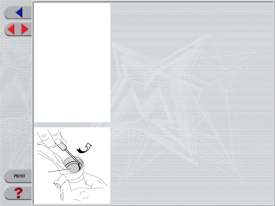
FIG. 13
Fit the bit of a small screwdriver into the
upper edge slot of the guide bushing (26)
and lift gently. Pull the bushing out of the
slider and make all necessary changes.
26

Super T
QR20
26
25
REASSEMBLY
CAUTION: before reassembling, all metal
components should be washed carefully
with inflammable and biodegradable sol-
vent and dried with compressed air.
GUIDE BUSHING AND SEAL
ASSEMBLY
FIG. 14
Check that no dirt or debris is between
slider and bushing. Insert the guide bushing
(26) into place so that it adheres to the
slider.
FIG. 15
Fit the upper washer (25) into the slider so
that it touches the guide bushing.
FIG. 16
Lubricate the oil seal (24) and place it onto
the seal press (B) with the hollow side
toward the slider.
Press the oil seal into place until it touches
the lower washer by using the above seal
press.
24
B
Super T
QR20
23
22
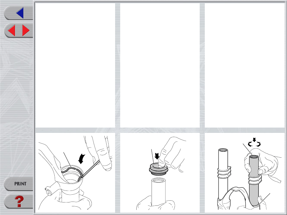
FIG. 17
Insert the stop ring (23) into the slider
making sure it is properly seated into place.
Use buffer (B) to properly seat the ring into
the slider.
FIG. 18
Lubricate the dust seal (22) and fit it into the
stanchion from the spring end.
FIG. 19
Fit the stanchion tube (28) gently into the oil
seal (24), together with dust seals.
Rotate the stanchion tube while inserting it
into the seal to reduce the chance of dam-
aging the seals.
Turn the slider over and check that cartridge
thread (21) is sticking out through the slider
hole.
Check to see that the stanchion tube slides
unrestricted by cycling the fork up and
down several times.
The tube should slide freely inside the seal
assembly without any side play.
In the event it is too hard or too soft, repeat
the previous steps described above and
check components to ensure they are not
damaged.
Seat the dust seal (22) on top of the slider.
28
22
Super T
QR20
21
35
34
Nm
11
HYDRAULIC CARTRIDGE
FIG. 20
Insert washer (36, see exploded view)
together with the complete hydraulic car-
tridge (21) with the stanchion pressed fully
down into the slider.
FIG. 21
Grease the O-ring (34) on the foot nut (35)
and screw the nut on the hydraulic cartridge
threaded end.
Tighten to 11 Nm.
Pump stanchion up and down several times
to make sure it slides properly through the
stroke.
HOW TO FILL WITH OIL
FIG. 22
Pour the oil little by little when the stanchion
tube is fully down and then pump with the
cartridge (21) rod so as to have a better
filling.
Cartridge is full when no air is detected
when pumping, in the fully compressed
position.
Check that the oil level is 80 mm from the
top of the stanchion tube in each leg.
80
21
Super T
QR20
9
8
16
10
37
8
5
6
21
18
SPRING AND CAP
FIG. 23
Fit the spring (37), the washer (8), the
spring (10), the preload sleeve (9) and the
top washer (8) into the stanchion tube.
Lubricate the O-ring (16) on the top of the
preload knob support and the O-ring (6) on
the cap (5).
FIG. 24
Move the plunger (7, see exploded view),
in the cap, to the minimum preload posi-
tion.
Screw the complete cap (5) onto the car-
tridge (21) rod.
Screw cap all the way in.
Tighten check nut (18) against cap (5).
FIG. 25
Take out stanchions and fit caps (5) by
hand.
Place the stanchions in a vice making sure
they are not damaged or dented and tighten
the caps to 20 Nm.
5
Nm
20
Super T
QR20
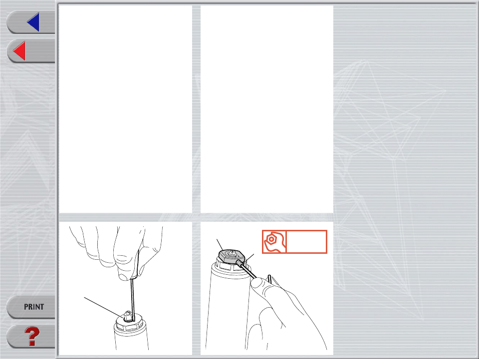
FIG. 26
Fit the stop ring (4) of the preload knob
support and make sure it is properly seated
into place.
FIG. 27
Fit the preload knob (2) and secure it on the
support by tightening the grub screw (3) to
1.5 Nm.
Install fork legs into crown and upper crown
as specified in section “INSTALLATION”.
4
Nm
1,5
2
3
Wyszukiwarka
Podobne podstrony:
2002 L Dj15 QR20 110
2002 L Dj1 QR20 110
2002 L jrT QR20 170
2002 L Z1 FR QR20 130
2002 L Z1 DO QR20 110
Ustawa z 30 10 2002 r o ubezp społ z tyt wyp przy pracy i chor zawod
SUPER DUPER
ecdl 2002
mikro wykresy super
Marvel Super Heroes Gates of What If Castle Doom Map
ei 03 2002 s 62
2002 09 42
2002 06 15 prawdopodobie stwo i statystykaid 21643
więcej podobnych podstron