T
his project came about as a con-
vergence of three things: First,
since I’ve been in the head-
phone amp business, I’d been
thinking about writing an article about
a do-it-yourself headphone amp. Sec-
ond, I had been hearing from quite a
few people who wanted to try to build
an audio project using tubes, but were
put off by the high voltages involved.
And third, I ran across some low-volt-
age tubes that were designed to run off
the battery voltage in car radios.
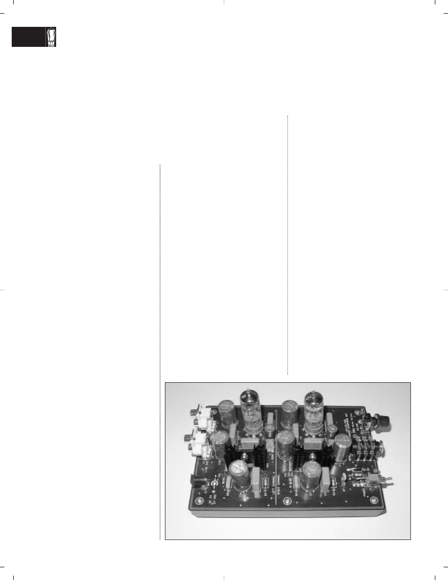
My goal in designing this amp
(
Photo 1) was to come up with an easy-
to-build, affordable project that’s safe
and fun for an inexperienced builder to
experiment with. I wouldn’t call it a
high-end audio design, but it does
sound pretty good. You can use it as a
headphone amplifier or as a line ampli-
fier to drive power amps.
This amplifier uses a single-ended
tube voltage amplifier stage and a solid-
state follower to get a low enough out-
put impedance to drive headphones. It
uses no negative feedback. I think this
type of circuit is a good introduction to
the sound of tube audio equipment.
LOW-VOLTAGE TUBES?
Most tube audio circuits—even low-level
preamps—operate on power supply volt-
ages of between 100 and 500V. With
proper precautions while building and
working on your equipment, these volt-
ages really shouldn’t be a safety haz-
ard—but nevertheless, they can deter
the inexperienced from attempting to
build tube equipment.
Most audio experimenters probably
don’t know that there was an entire
line of tubes designed to be operated
from a low-voltage power supply.
These tubes, sometimes called “space
charge” tubes, were designed during
the transition from tube to solid-state
electronics, mostly for use in 12V DC
automobile radios.
Automobile radios using high-voltage
tubes were expensive to manufacture,
because the low-voltage DC power (ei-
ther 6V or 12V) available in the car had
to be stepped up to a high voltage to op-
erate the tubes. With AC power, this is
just a matter of a transformer and rectifi-
er; with a DC input, the battery voltage
first had to be turned into a square-wave
alternating current by the use of a “vi-
brator,” an electromechanical device
that operates a bit like a buzzer or relay.
When transistors were first commer-
cially available, radio-frequency transis-
tors were expensive and difficult to
manufacture, so hybrid tube-transistor
car radios were developed. Most often,
these radios employed tubes in the RF
and low-power audio stages, and a ger-
manium power transistor to act as the
final audio stage, to drive the low-im-
pedance loudspeaker. This hybrid low-
voltage tube plus transistor approach
was used only for a short time before
fully transistorized radios became cost-
effective, making the hybrid low-voltage
tube radios obsolete.
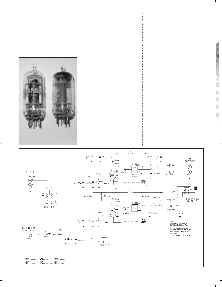
Because of their target application,
many of the low-voltage tubes are RF
tetrodes and pentodes. Fortunately for
us tube audio fanatics, there is also a
whole line of tubes that contain a small-
signal audio triode plus two diodes.
These tubes were used as the detector,
AVC, and first audio stage in a typical
AM radio. This is the type of tube I used
in this design. There are several inter-
changeable types to choose from, and
they are inexpensive and readily avail-
able. Two such tubes, a 12AE6A (left)
and 12FM6, are shown in
Photo 2.
The headphone/line amplifier pre-
sented here takes a similar approach to
those old car radios: a low-voltage tube
is used to amplify the audio signal, and
a solid-state output stage is used to pro-
vide a low-impedance drive for head-
phones or a power amplifier.
Here’s a simple, safe, inexpensive project for beginners and those who
wish to “try tubes.”
By Pete Millett
Build a Low-Voltage Tube Hybrid
Headphone/Line Amp
20 audioXpress 11/02
www.audioXpress.com
PHOTO 1: The low-voltage hybrid headphone amp.
THE CIRCUIT DESIGN
Refer to the schematic diagram (
Fig. 1),
as I walk you through the circuit and
describe how it works.
Input Stage
The audio input from J4 is fed to a 50k
Ω
volume control potentiometer, RV1.
The output of the volume control is con-
nected directly to the tube’s grid, so the
DC voltage on the grid is 0V.
The triode of a space-charge triode/
dual diode tube is used in a normal
grounded-cathode voltage amplifier cir-
cuit. There are several such tubes that
you can use; I tried the 12AE6 (or
12AE6A) and the 12FM6. Other tubes
that may work, and all with the same
pinout, include the 12AJ6, 12EL6,
12FK6, and 12FT6. Since the diode sec-
tions are unused, they are simply tied
to ground.
Bias for the tube stage is developed
across an adjustable resistor (R2, R6),
which is paralleled by both an elec-
trolytic capacitor and a film capacitor.
DC current flowing through the tube
raises the cathode voltage above the
grid, which provides negative bias for
the tube. The capacitors provide a low-
impedance path for the audio signal.
Note that the exact value of these ca-
pacitors is not at all critical.
The plate of the tube is loaded with a
0.56mA constant-current diode (D3,
D4). You can think of this part as a re-
sistor, which varies its resistance to try
to keep a constant current flowing
through it. The effect of this is to pre-
sent a very high AC impedance load to
the plate of the tube, which allows the
tube to operate at high gain and low
distortion. It also allows the plate to
swing very close to the power-supply
voltage.
There’s nothing sacred about using
0.56mA as the plate current—looking at
the plate curves, I thought it looked like
a good point to operate the 12AE6 tube.
I also tried a 1mA part, and got slightly
higher distortion. You may want to try
different currents, especially if you use
tubes other than the ones I tried.
You can also experiment with using
a resistor in place of the constant-cur-
rent diode as a plate load. I tried resis-
tors in the 47k to 100k range. I found
that I achieved lower distortion and
higher output levels with the constant-
current diode. I didn’t do extensive lis-
tening tests with the resistor load,
though.
The DC voltage present (with no sig-
nal) on the plate of the tube varies, de-
pending on the setting of the bias resis-
tor. I’ll discuss this setting in detail
later, but normally this voltage is be-
tween 12V and 20V.
Output Stage
The plate of the tube is directly coupled
to a unity-gain buffer amplifier IC, the
PHOTO 2: Low voltage triode/dual diode
tubes 12AE6A (left) and 12FM6.
FIGURE 1: Schematic diagram.
G-2115-1
22 audioXpress 11/02
www.audioXpress.com
BUF634, which is made by Burr Brown
(now owned by Texas Instruments).
The BUF634 is a follower, meaning that
it has no voltage gain; the output volt-
age is the same as the input voltage. It
has very low output impedance, and
can provide up to 200mA of current
from its output. Its input impedance is
very high, so it doesn’t load the tube
stage significantly.
For those familiar with the BUF634,
this application seems a bit strange.
The typical use of the BUF634 is to be
connected to the output of an op amp to
boost its current capability. Normally, it
is placed inside a feedback loop and is
powered with bipolar (positive and neg-
ative) power supplies. Here, the
BUF634 is used as an open-loop buffer,
powered with a single positive supply.
The DC coupling to the plate is re-
quired to provide the DC bias needed
for the BUF634 to operate.
Normally, with no connection made
to the BW pin, the BUF634 operates in
a very low quiescent current mode. If
you desire, you can operate the BUF634
in a wide-bandwidth, high-bias mode,
by connecting the BW pin to ground (at
JP1 and JP2). This lowers the open-loop
distortion of the part ever so slightly.
The difference in THD is barely mea-
surable, but I found that the character of
the distortion did change. In the high-
bias mode, I saw fewer odd harmonics.
This is the mode that I used, but feel free
to experiment with both settings.
The output of the BUF634 is con-
nected through a 22
Ω
resistor, which is
needed only to help protect the
BUF634 in case of a short circuit of the
output, but it also affects how different
headphones sound. I usually recom-
mend a series resistor of between 10%
and 50% the impedance of your head-
phones—e.g., if you have 200
Ω
head-
phones, use a resistor between 20 and
100
Ω
. If you don’t know what imped-
ance your headphones are, or are
going to use several different head-
phones, stick with a smaller resistor
(such as 22
Ω
). Again, you can experi-
ment with this resistor value to see
what differences you hear without wor-
rying about hurting anything. For line
amp use, the value of the resistor
makes very little difference.
Since the BUF634 is being operated
with a single-ended power supply, its
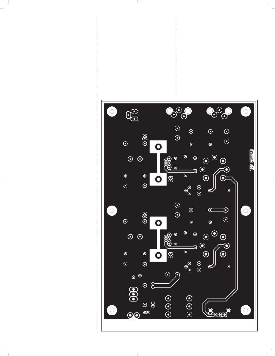
PHOTO 3: Bare PC board.
TABLE 1
PARTS LIST
REFERENCE
DESCRIPTION
MANUFACTURER/PN
DISTRIBUTOR/PN
COST EACH
C1, C7, C9, C10, Capacitor, electrolytic,
Elna ROA 100
µ
F Welborne
$2
C16, C18, C19
100
µ
F 100V
100V
ROA102
C2, C11
Capacitor, electrolytic,
Elna ROA 220
µ
F
Welborne
$0.80
220
µ
F 16V
16V
ROA221
C3–C5, C8,
Capacitor, film,
Wima MKP10 0.22
µ
F
Welborne
$1.80
C12–C14
0.22
µ
F 50V
160V
WM214
C6, C15
Capacitor, axial ceramic,
generic
Digi-Key
$0.12
0.01
µ
F 50V
1103PHCT
D1
LED, right-angle
Dialight
Digi-Key
$0.69
PCB mount
550-0205
350-1002
D2
Transient suppressor,
P6KE30A
Digi-Key
$0.47
P6KE30 P6KE30ADICT
D3, D4
Current regulator
1N5291
Mouser
$1.78
diode, 1N5291
610-1N5291
HS1, HS2
Heatsink, PCB
Aavid
Digi-Key
$1.20
mount
531002B02500
HS190
IC1, IC2
IC, buffer,
TI BUF634T
Digi-Key
$6.20
BUF634T
BUF634T
J1
Jack, ¼
″
Rean
Mouser
$1.36
headphone
550-22302
J2
Jack, DC power,
CUI-Stack
Digi-Key
$0.38
2.5mm pin
CP-102B
CP-102B
J3, J4
Jack, dual RCA
DGS
Mouser
$0.57
161-4219
PF1
PTC fuse, RXE050
Raychem RXE050
Digi-Key
$0.59
RXE050
R1, R3, R5,
Resistor, 1k
Ω
generic
Mouser
$0.21
R7, R8
¼W
71-RN60D-F-1.0K
R2, R6
Trimpot, 5k
Ω
Bourns 3266W
Digi-Key
$3.58
3266W-502
R4, R9
Resistor, 22
Ω
generic
Mouser
$0.21
¼W
71-RN60D-F-22.1
RV1
Potentiometer,
Panasonic
Digi-Key P2Y7503
$2.53
stereo audio, 50k
Ω
S1
Switch, toggle,
C&K
Digi-Key
$4.50
PC mount
CKN1059
VT1, VT2
Tube, 12FM6 or
AES 12FM6 or
$3.10
12AE6A (see text)
12AE6A
at VT1, VT2
Tube socket, 7-pin mini
AES P-ST7-195
$0.50
at RV1
Knob, press-on
Rean
Mouser
$0.46
6mm shaft
550-67001
Case, plastic
Serpac 071I
Digi-Key
$8.88
SR071-IB
Wall supply, 24V
CUI-Stack
Digi-Key
$8.75
DC 400mA
DPD240040-P6P
T520-P6P
PCB
$20
Total: $100.18
24 audioXpress 11/02
www.audioXpress.com
output sits at a DC voltage above
ground (the same as the tube plate). To
connect to headphones or other audio
equipment, the DC must be removed
with a coupling capacitor. I used an
audio-grade 100
µ
F electrolytic capaci-
tor, paralleled by a small film capacitor.
The exact value of these caps is not
critical, but it does set the low-frequen-
cy response limit of the amplifier. For
most headphones, anything over
47
µ
F is adequate. The output side of
the capacitors then connects to both
the headphone jack (J1) and an RCA
line output jack (J3).
Power Supply
Input power is provided by a 24V DC
wall-mount supply through the DC
input connector, J2. By using an off-
the-shelf DC wall adapter, there’s no
AC line voltage present anywhere in
the headphone amplifier, so it’s very
safe. The supply does not need to be
regulated; any voltage between 20V
and 28V is fine.
The DC power is controlled by the
power switch S1, and then flows
through a PTC fuse device, PF1. This
device is like a fuse, in that when too
much current flows through it (in
this case, over 500mA), it becomes
an open circuit, stopping current
flow. It is different from a fuse in that
once it has a chance to cool off, it re-
covers and closes the circuit again.
D2, which is connected between
the PTC fuse and ground, is a 30V
transient protection diode. Forward
biased (anode positive), it conducts
current like a normal diode; reverse
biased (anode negative), it does not
conduct until 30V is exceeded, at
which point it conducts. The pur-
pose of this device, in conjunction
with the PTC fuse, is to protect the
circuit from the connection of a DC
supply that either is wired with the
wrong polarity or exceeds 30V. In ei-
ther case, the transient protector
will conduct, essentially shorting
the supply, which will cause the
PTC fuse to open.
A power-on LED, D1, and its cur-
rent limiting resistor, R1, provide a
visual power-on indicator. C1 acts as
a filter, helping lower noise and hum
coming in on the DC power.
The 24V DC power is applied to
the filaments of the two tubes, which
are connected in series. As long as the
two tubes are the same, each filament
will get one half of the 24V supply, or
12V. Note that the tubes designed for
car radios are designed to work correct-
ly with any voltage between 10 and 16V
on their filaments.
The 24V DC power is also used to
provide power to the two BUF634 am-
plifier ICs. This power is decoupled, or
filtered, with several capacitors in par-
allel—an electrolytic capacitor, a film
capacitor, and a ceramic capacitor.
The reason for this is to provide a low
impedance over a wide frequency
range to the IC. Each type of capacitor
has a low impedance over a different
frequency range, and paralleling them
accomplishes this.
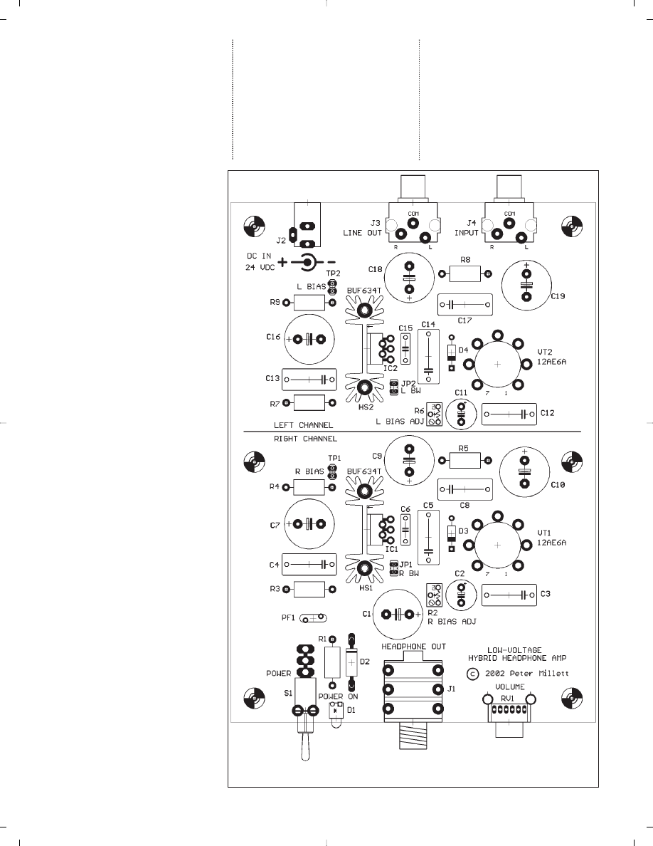
FIGURE 2: PCB component layout (PCB size: 4.75
″ ×
6.75
″
).
G-2115-2
26 audioXpress 11/02
www.audioXpress.com

Power for the voltage amplifier tube
stage is further filtered by a 1k resistor
and another 100
µ
F electrolytic capaci-
tor, paralleled by a small film cap. The
tube stage is sensitive to hum or noise
on the power supply, so this filter pre-
vents any ripple or noise present on
the supply from being amplified and
appearing at the output. The decou-
pling also prevents any feedback from
the output stage to the input stage
caused by perturbations of the power
supply.
CONSTRUCTION
Since my goal with this project was to
do something that would be easy to
build, I designed a printed circuit
board (PCB), which contains all of the
components, including input and out-
put connectors and the volume control
(
Photo 3).
Assembly
Assembly is a simple matter of inserting
the components into the PCB, soldering
the leads to the board, and trimming any
excess wire from the back. Make sure
that you install the electrolytic capaci-
tors and diodes in the right orientation,
matching the designation on the PCB.
The BUF634 buffers are bolted to
small PCB-mount heatsinks. I found
that even in high-bias mode, they run
barely warm to the touch during nor-
mal operation, but the heatsinks will
help protect the part in the event of a
short-circuited output.
Since there are no dangerous high
voltages present, I designed the PCB to
mount into one half of an inexpensive
plastic instrument case, with the top
side of the PCB exposed. I just mounted
the board into one half of the enclosure
and discarded the other half (
Photo 1).
This made a simple, easy way to mount
the PC board, and still allow access to
the board to adjust bias, change tubes,
and make measurements. You could
also mount the PCB into a more con-
ventional metal box if you choose.
Once the PCB is assembled and
mounted to the plastic case, all you
need to do is install the tubes into their
sockets, plug in the power supply, and
adjust the tube bias as detailed later. Of
course, the more experienced builder
could also build this project using con-
ventional point-to-point wiring inside a
chassis.
Parts
I used only parts that are readily avail-
able for a reasonable cost from mail-
order distributors that cater to hobby-
ists.
Table 1 is a listing of all the parts
used, where I purchased them, and
about what they cost. Refer to the con-
tacts listing at the end of the article for
information on how to get in touch with
the vendors listed.
The parts list is all-inclusive, includ-
ing the plastic enclosure, volume con-
trol knob, and so on. You can see that
the entire project can be assembled for
about $100. The only tools you’ll need
are a screwdriver, wire cutters, and sol-
dering iron. You’ll also need a volt-
meter (any analog or digital meter will
do) to set the bias, which I’ll describe
later.
Exact part selection is not at all criti-
cal. Capacitors should be rated for at
least 50V, except the cathode bypass ca-
pacitors, which can be rated as low as
16V. Capacitance values can vary be-
tween about 50% and 200% of the values
audioXpress November 2002 27
4470 Avenue Thibault
St-Hubert, QC J3Y 7T9
Canada
SOLEN INC.
Tel: 450.656.2759
Fax: 450.443.4949
Email: solen@solen.ca
WEB: http://www.solen.ca
[ y
COMPONENTS:
SOLEN HEPTA-LITZ
AND STANDARD
INDUCTORS AND
CAPACITORS - THE
CHOICE OF MANY
HIGH-END SPEAKER
MANUFACTURERS.
HARDWARE:
POWER RESISTORS,
L-PADS, CABLE,
ABSORBING AND
DAMPING MATERIALS,
GOLD SPEAKER
TERMINALS, GOLD
BANANA PLUGS AND
BINDING POSTS, GRILL
FASTENERS, PORT
TUBES AND TRIM
RINGS, PAN HEAD
SCREWS, SPIKES
AND TEE NUTS WITH
ALLEN HEAD BOLTS
AND PLENTY MORE...
Solen crossover components -
used by the most discriminating
loudspeaker manufacturers.
S O L E N H E P TA - L I T Z I N D U C T O R S
Air Cored Inductors, Litz-Wire Perfect Lay Hexagonal Winding
Values from .10 mH to 30 mH
Wire Size from 1.3 mm (16AWG) to 2.6 mm (10 AWG) 7 Strands
S O L E N S TA N D A R D I N D U C T O R S
Air Cored Inductors, Solid Wire Perfect Lay Hexagonal Winding
Values from .10 mH to 30mH
Wire Size from 0.8 mm (20AWG) to 2.6 mm (10 AWG)
S O L E N F A S T C A PA C I T O R S
Fast Capacitors, Metalized Polypropylene
Values from 0.10 µF to 330 µF
Voltage Rating: 630, 400, 250 VDC
C R O S S O V E R A N D S P E A K E R PA R T S
Metalized Polyester Capacitors, 1.0 µF to 47 µF, 160 VDC, Non Polar
Electrolytic Capacitor, 22 µF to 330 µF, 100 VDC, Power Resistors
10 W, 1.0
Ω
to 82
Ω
, 8
Ω
L-Pads plus all the hardware and supplies
to complete any speaker project.
O R D E R T H E F R E E S O L E N C A T A L O G A N D C D .
F O R W A R D Y O U R R E Q U E S T B Y P H O N E , F A X ,
M A I L O R E M A I L - O R F I L L I N T H E O N L I N E
R E Q U E S T F O R M A T S O L E N . C A .
I used with little change. Resistors, too,
can be anything close to what I used
with not much effect.
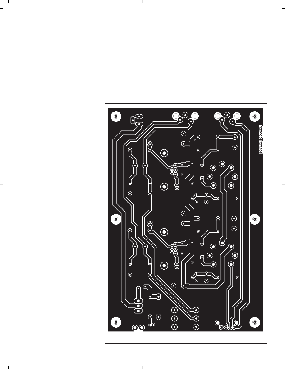
The PCB
I hope to be able to provide bare PCBs
for sale to individuals who want to
build this project. You can also make
your own, or have them made in small
quantity for a reasonable amount of
money at prototype PCB vendors who
specialize in small runs.
Figure 2 shows the top side of the
PCB, showing parts placement.
Figures
3 and 4 are the top foil and bottom cop-
per foil layers. You can also download
the artwork files from the author’s web-
site at: www.pmillett.addr.com.
SETTING THE BIAS
I decided to make the bias voltage for
the tubes adjustable, partly so you
could easily try out different tubes, and
partly so you could try different operat-
ing points for the tubes. Since the bias
voltage is just developed across the
cathode resistor, making this resistor a
trimmer potentiometer provides an
easy way to vary the bias.
If you measure the voltage at the out-
put of the BUF634 with no audio ap-
plied (which is the same DC voltage as
on the plate of the tube), you can set the
operating point of the tube by adjusting
the bias trimpot. Measuring at the out-
put of the BUF634 guarantees that the
voltmeter won’t load the voltage on the
high-impedance plate.
Since the plate load is a 0.56mA con-
stant-current diode, moving the bias
point around does not affect the plate
current. If you substitute a resistor for
the constant-current diode, you can
still adjust the bias in the same man-
ner, but the plate current will vary with
the bias setting.
Setting the bias is a great way to ex-
periment with the “sound” of different
tube distortion. For example, as you ad-
just the bias to get a progressively lower
plate voltage, you get more and more
“single-ended” second harmonic distor-
tion. As you raise the voltage to one half
the supply voltage, you can get a higher
output voltage before clipping, at the ex-
pense of higher third-harmonic distor-
tion at lower levels. Raising the voltage
further lowers the distortion products at
low signal levels at the expense of a
lower maximum output level.
I looked at the distortion products of
the output using an audio analyzer, but
you really don’t need sophisticated test
equipment to set the bias on your am-
plifier. If you just put a voltmeter on the
bias test points, you can adjust the bias
based on the DC voltage you measure
there. Then, use your ears to evaluate
the result. I found that you really can
hear differences in sound with chang-
ing the bias, especially in low-level
detail.
With both the 12AE6 and 12FM6
tubes that I tried, adjusting the bias to
one-half the input power-supply voltage
provided mostly symmetric clipping,
and the highest output voltage. My wall
supply was putting out 27V, so I set the
bias to 13.5V.
Photo 4 shows what the
output looked like at this bias setting,
using a 12FM6 tube, driven hard into
clipping.
Note that clipping is nearly symmet-
rical, but the top of the waveform is
clipped more abruptly than the bottom.
This is the point where the output hits
the positive power-supply rail.
Photo 5 shows the output signal and
distortion residual (what’s left of the
FIGURE 3: PCB top copper.
G-2115-3
28 audioXpress 11/02
www.audioXpress.com
signal after you cancel out the original
input signal) for a 1kHz, 1V RMS output
with the same bias. The residual,
shown at a much higher scale than the
output signal, is very nearly a sine wave
at a frequency of 2kHz. This indicates
that the distortion is primarily second
harmonic.
If you adjust the bias voltage lower
than one-half the supply voltage, you
can avoid the sharp clipping at the top
of the waveform—but distortion increas-
es dramatically, since the tube be-
comes very nonlinear as the grid be-
gins being driven positive with respect
to the cathode. If you adjust the voltage
above one-half the supply voltage, you
can reduce the distortion at 1V RMS
out, at the expense of slightly decreas-
ing the maximum output that can be
obtained before clipping.
Photo 6 shows the waveform in
heavy clipping at a bias voltage of 19V.
You can see that the top of the wave-
form is more clipped than in
Photo 4.
However, the distortion at 1V RMS out
is actually slightly lower (
Photo 7). I
found this bias setting to be much more
pleasurable to listen to than the lower
plate voltage bias point.
CIRCUIT PERFORMANCE
For those not used to tube circuits, the
CT101 key specifications
Gain (selectable)
0, 6 or 12
dB
25
MHz
Slew rate (at 0dB gain)
500
V/uS
S/N ratio (IHF A)
112
dB
THD
0.0002
%
Output resistance
0.1
ohm
Channel matching
± 0.05
dB
PCB dimensions:
100 x 34
mm
3.97 x 1.35 "
General attenuator specifications
Number of steps:
24
Bandwidth (10kOhm):
50
MHz
THD:
0.0001
%
Attenuation accuracy:
±0.05
dB
Channel matching:
±0.05
dB
Mechanical life, min.
25,000
cycles
Fax: (+66) 2 260 6071
E-mail: info@DACT.com
g
with a stereo CT1 attenuator added.
CT100 key specifications
Gain (selectable):
40 to 80
dB
RIAA eq. deviation:
± 0.05
dB
S/N ratio (40/80dB gain): 98/71
dB
THD:
0.0003
%
Output resistance:
0.1
ohm
Channel separation:
120
dB
Bandwidth:
2
MHz
PCB dimensions:
105 x 63
mm
4.17 x 2.5 "
CT2 6-gang
volume control for A/V Audio
audioXpress November 2002 29
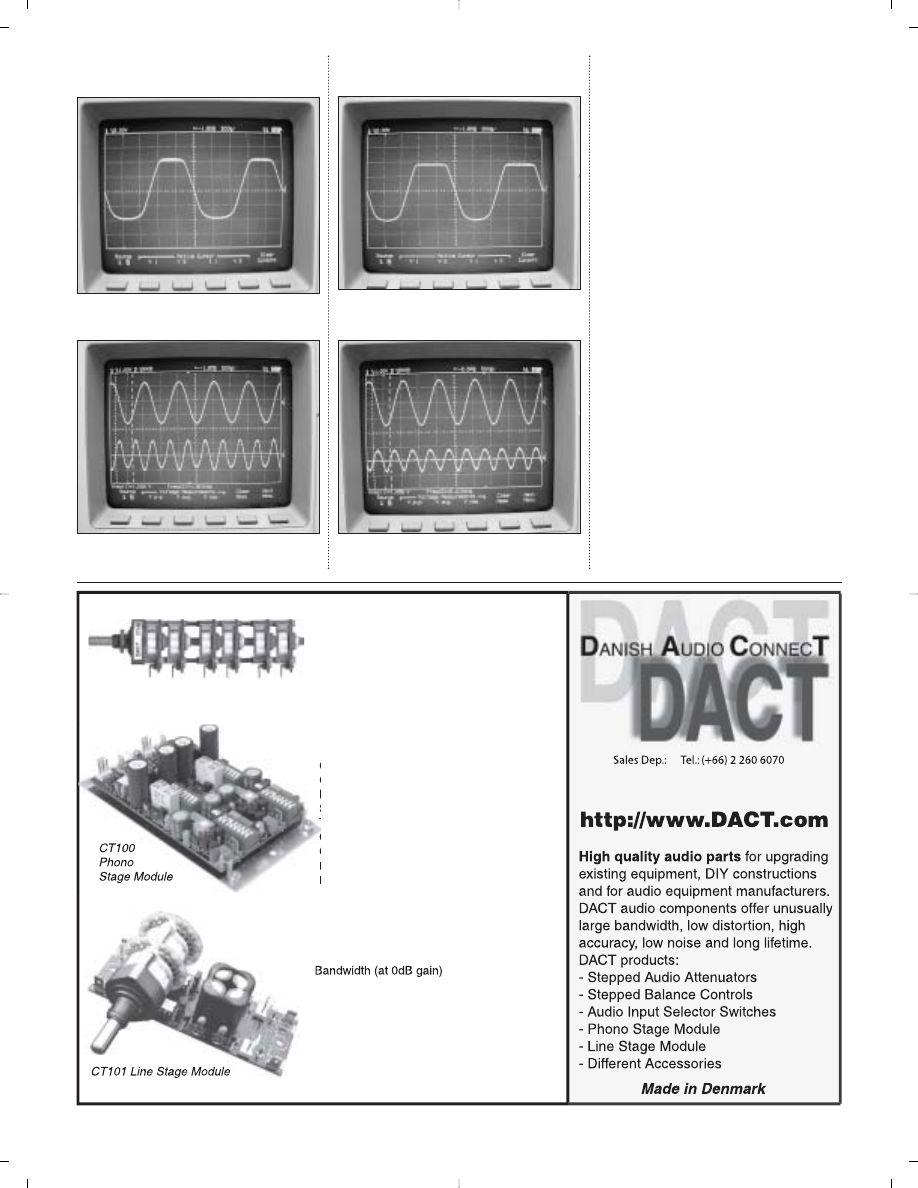
PHOTO 4: 12FM6, 13.5V bias driven to
clipping.
PHOTO 5: 12FM6, 13.5V bias, 1V RMS out
(top) and distortion residual (bottom).
PHOTO 6: 12FM6, 19V bias driven to clip-
ping.
PHOTO 7: 12FM6, 19V bias, 1V RMS out
(top) and distortion residual (bottom).
distortion figures that follow will seem
large. Indeed, this is not a low-distor-
tion amplifier, but THD alone is not
much of an indicator of perceived sonic
performance. In fact, I believe that
much of the appealing sound of a sin-
gle-ended triode amplifier has to do
with the introduction of second-order
harmonics into the music. That’s one of
the purposes of this project—to allow
you to listen to, and experiment with,
this distortion.
I made distortion measurements of
the amplifier, using both a 12AE6A
tube and a 12FM6 tube, at two different
bias settings, both using a 0.56mA con-
stant-current diode as the plate load.
Here are the results:
12AE6A, bias
=
13.5V
Maximum output at clipping: 2.7V RMS
Maximum output, 5% THD: 1.8V RMS
THD, 1V RMS out: 0.6%, largely third
harmonic
12AE6A, bias
=
19V
Maximum output at clipping: 2V RMS
Maximum output, 5% THD: 2V RMS
THD, 1V RMS out: 0.5%, virtually all sec-
ond harmonic
12FM6, bias
=
13.5V
Maximum output at clipping: 3V RMS
Maximum output, 5% THD: 2V RMS
THD, 1V RMS out: 1.5%, mostly second
harmonic
12FM6, bias
=
19V
Maximum output at clipping: 2V RMS
Maximum output, 5% THD: 1.7V RMS
THD, 1V RMS out: 1%, virtually all sec-
ond harmonic
The relatively low maximum output
levels are limited by the low plate volt-
age used on the tubes. You can experi-
ment with different tubes, different bias
settings, and different constant-current
diodes, and probably find operating
points different than the ones I used
that may provide higher output, and/or
lower distortion.
For most headphones, the output
from this amp is adequate to drive to
quite loud listening levels. With
Sennheiser HD600, Beyerdynamic
DT831, and Grado SR60 headphones,
there was ample output before distor-
tion to well beyond the loudness that I
can tolerate. This was verified both by
ear and by looking at the waveforms to
verify that the amp was not driving any-
where near clipping.
With my AKG K240 headphones, the
amp couldn’t drive as loud before
reaching the onset of clipping. These
are 600
Ω
impedance headphones,
which require quite a lot of voltage. I
would say this amp was marginally ac-
ceptable driving them.
Just for comparison, I measured the
output level at the headphone jack of
two portable CD players. With the first
unit, a brand new midrange player, I
could not drive the headphone output
to clipping. The maximum output level,
with a 0dBFS test CD, was 0.4V RMS. I
could drive the second CD player, an
older and more expensive unit, into
hard clipping at 3V RMS.
As a line amplifier, the output of this
amp should be more than adequate to
drive all but the most insensitive power
amps. Its low output impedance should
be able to drive just about any intercon-
nect cable.
The frequency response measured
very flat, within
±
0.1dB from 20Hz
−
20kHz, into a 200
Ω
load. At 100kHz, the
30 audioXpress 11/02
www.audioXpress.com
FIGURE 4: PCB bottom copper.
G-2115-4
limit of my audio analyzer, the output
was down only 0.8dB. Into a lower im-
pedance load, the low-frequency re-
sponse will drop a little, since the output
is coupled through a capacitor. With the
100
µ
F capacitor I used, you can expect
about
−
3dB into a 30
Ω
load at 20Hz.
I measured the noise at the output
(terminated in a 200
Ω
load) with
no input signal at 200
µ
V. This was
an un-weighted measurement, which
corresponds to
−
74dB below 1V RMS,
very near the measurement limit of my
test setup. This is very quiet for a tube
amplifier.
CONCLUSION
I’d be lying if I were to tell you that this
is the best-sounding headphone amp
I’ve ever listened to. But I’ve listened to
dozens of headphone amps, some of
which cost more than the average new
car. This amp does well, considering its
cost and the design compromises I
made. It will certainly be an improve-
ment over what you would hear with
headphones plugged into a portable CD
player. And being a fan of tube sound
myself, I think it sounds a whole lot bet-
ter than one of those $350 “op-amp in a
wooden box” audiophile headphone
amps.
The main goal with this project is not
to build a headphone amp, but rather to
build a project that can be a positive
learning experience for someone who’s
just getting started with building and
designing audio equipment. I think
from that perspective, this design is a
success: It’s an easy, inexpensive proj-
ect that will allow you to experiment
with the sound of tubes.
❖
audioXpress November 2002 31
CONTACTS
Antique Electronics Supply (AES)—tubes, tube
sockets, capacitors, and so forth.
www.tubesandmore.com
(480) 820-5411
Welborne Labs—resistors, capacitors, audiophile
parts, and so on.
www.welbornelabs.com
(303) 470-6585
Digi-Key—full-line parts distributor
www.digikey.com
(800) 344-4539
Mouser Electronics—full-line parts distributor
www.mouser.com
(800) 346-6873
Pete Millett—author
www.pmillett.addr.com
pmillett@hotmail.com
TURBOCHARGING YOUR REGA ARM
“Nothing less than total dynamite”
HI-FI WORLD MAGAZINE
If you are the proud owner of any Rega arm why not utterly transform it
into the league of super arms with the Origin live structural modification:-
$91. This modification will enable your Rega to perform at a level
exceeding that of arms costing over $1700. Rewiring with high grade litz
cable is also offered at an additional $85 and external rewiring is $99. All
these modifications are available in kit form if you wish to do the job
yourself or you can send us your arm for us to do the work.
"I have to say the Rega modifications turn this humble arm into a real
Giant killer. Gone is the rather grey, sterile sound of the cooking Rega.
Instead, tonal colour is fresh, dynamics have great speed and impact, and
the sound stage is huge." HI FI WORLD SUPPLEMENT (structural
modification to an RB250)
WHAT HI-FI MAGAZINE gave this modification a 5 star rating.
For arm modifications we normally turn around your arm in 1 - 2 days
FULL INFORMATION ON WEB SITE OR CONTACT:-
Origin live, 87 Chessel Crescent,Bitterne, Southampton SO19 4BT
Tel: 023 80442183 / 80578877 Fax: 023 80398905
E MAIL: originlive@originlive.com WEB SITE: http://www.originlive.com
OTHER KITS &
ROM ORIGIN LIVE INCLUDE:-
¾
TURNTABLES (Kits & Retail)
“the best sounding deck here...sounds
fantastic” WHAT HI-FI MAGAZINE” group
comparison test of 8 leading turntables
¾
SIlVER 250 TONEARM $729
Probably the best tonearm available at any
price (except for the Silver Taper).
¾
SILVER TAPER TONEARM $1491
¾
DC MOTOR UPGRADE
suitable to upgrade all turntables including
Linn Lingo, Armageddon, Roksan, Thorens,
Ariston, Rega, Systemdek etc $319
Well reviewed as a massive upgrade for all
turntables
PRODUCTS
F
D
URIN HE
MONTH
OF
N
OVEMBER
,
BUY
ANYTHING
FROM
OUR
WEB
STORE
AND
RECEIVE
10%
OFF
! S
IMPLY
PLACE
YOUR
ORDER
THROUGH
OUR
WEB
STORE
AND
USE
A
COUPON
CODE
OF
:
SALE
You will receive
10% off your entire
order! Good for
November 2002 only!
THANKSGIVING DAY
Adire Audio carries a full range of kits, products,
and services for the DIYer. Please contact us at:
ADIRE AUDIO
WWW.ADIREAUDIO.COM
PH/FAX: 206-789-2919/800-437-2613
AX-NOV-SALE
T
G
Wyszukiwarka
Podobne podstrony:
DoZ Headphone Amp
Alton full class A headphones amp
Mike Holt Guide to Low Voltage Systems
Home Power Magazine Extract Low Voltage Battery Disconnect
Low Voltage Power Supply Circuits
High Current, Low Voltage Shunt Regulator
Designing With Low Dropout Voltage Regulators
SP6FIN 160m HF receiver ECC82 low power supply voltage
Build A 10 Amp 13 8 Volt Power Supply
99 Voltage and Current Feedback Op Amp Comparison
100 Voltage Feedback Op Amp Compensation
Biochemia TZ wyklad 12 integracja metabolizmu low
O'Reilly How To Build A FreeBSD STABLE Firewall With IPFILTER From The O'Reilly Anthology
AMP E 323
HF 91110 80 Amp Inverter Arc Welder
Micele na?lowniku
Łow
L 5357 Dress with low cut neckline
Induction Generator Based System Providing Regulated Voltage With Constant Frequency
więcej podobnych podstron