1
Interface module
MIM-B14
2
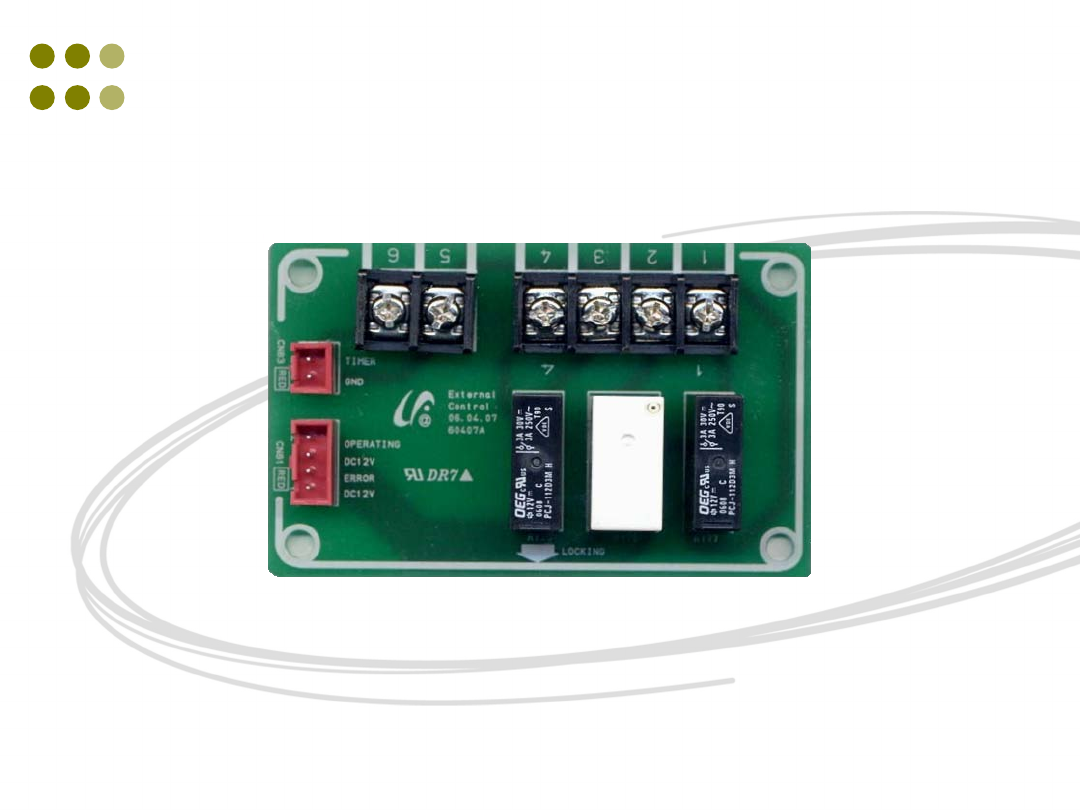
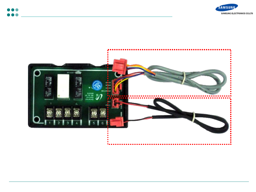
Contact interface module – MIM-B14
- Components
State output cable
Control input cable
Interface module
3
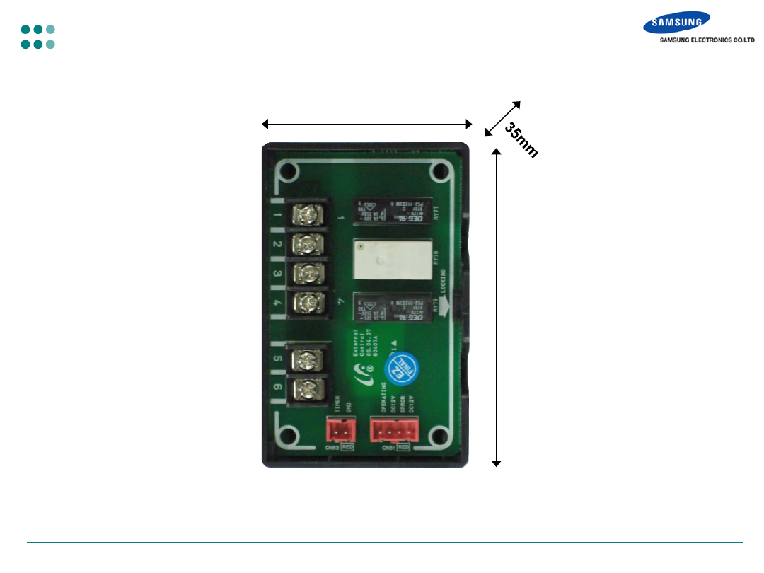
- Dimensions
80mm
50mm
Contact interface module – MIM-B14
4
- MIM-B14
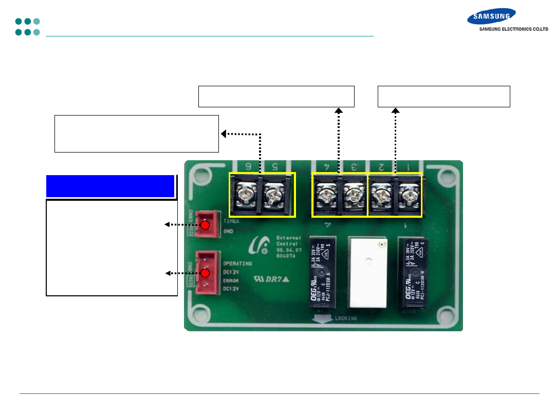
Contact interface module – MIM-B14
Control input contact
Indoor unit state
(Operation, Error)
To indoor unit PCB
External control input contact
(voltage-free)
Indoor unit operation output
Indoor unit error output
5
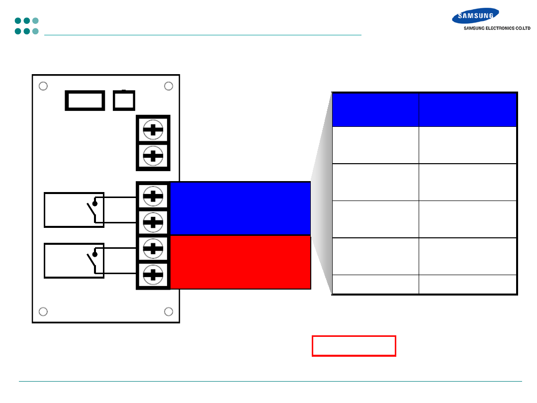
- MIM-B14
Contact interface module – MIM-B14
250VAC, 3A
250VAC, 3A
Operation state
Close : Indoor unit ON
Open : Indoor unit OFF
Error state
Close : No Error
Open : Error
Indoor unit
Operation
Operation state
Cooling
(Thermal
ON
)
Close
Cooling
(Thermal
OFF
)
Open
Heating
(Thermal
ON
)
Close
Heating
(Thermal
OFF
)
Open
FAN
Open
NOTE : Indoor unit operation/error output : Voltage-free relay contact
6
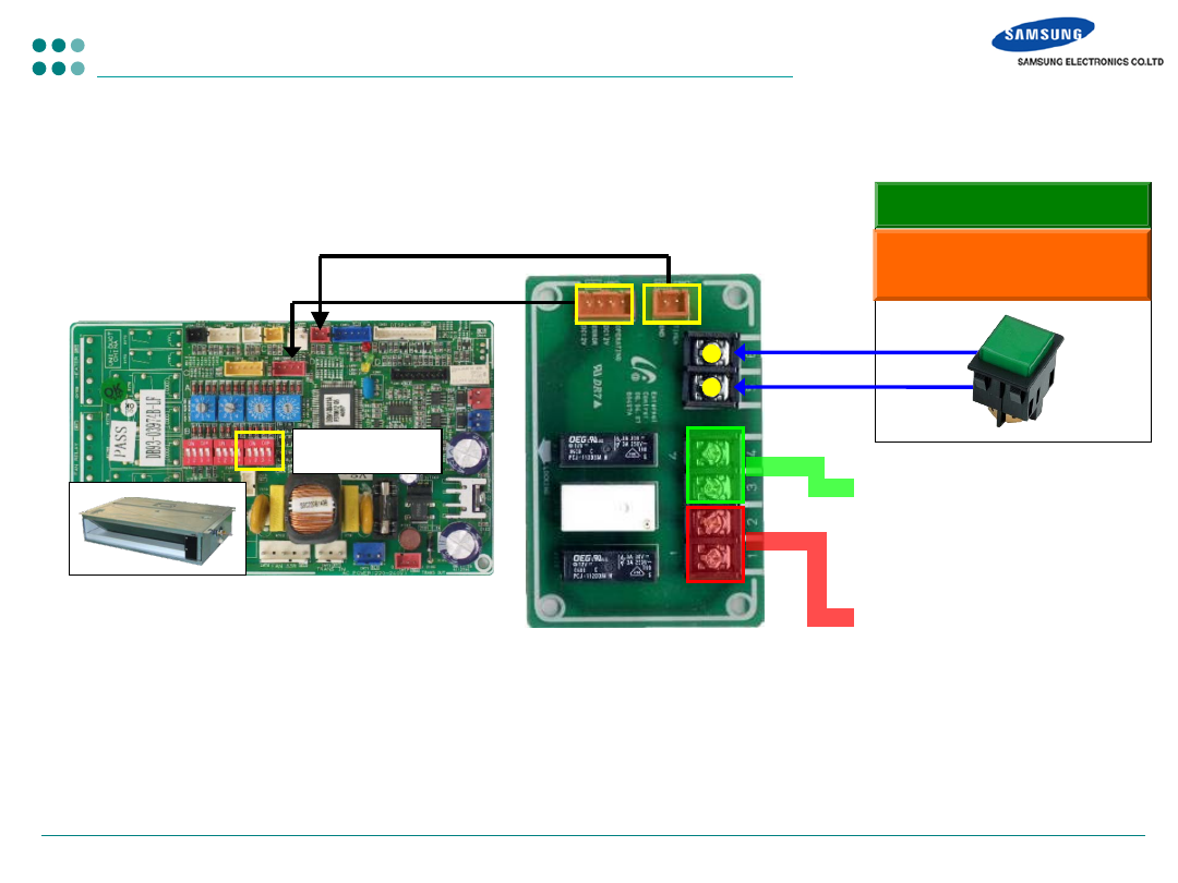
Contact interface module – MIM-B14
- Connection to indoor unit
To control the indoor unit and make synchronous control with other
devices through the external contact input/output signal
External input
Contact Output (operation)
- Close : Indoor unit ON
- Open : Indoor unit OFF
Contact Output (error)
- Close : No Error
- Open : Error
ON/
OFF
Indoor unit option switch K11 – ON : external control enabled, OFF : disabled
Input load – 5V, 5mA, Output load - 250VAC, 3A
Applied indoor units : DVM Plus III (HR) Slim 1way, 2/4way, mini 4way, DUCT, Ceiling
Initial operation : Auto mode, temperature setting : 24, Auto fan speed, Stop airflow direction
Closed : Indoor unit ON
Open : indoor unit OFF
K11 : OFF
7
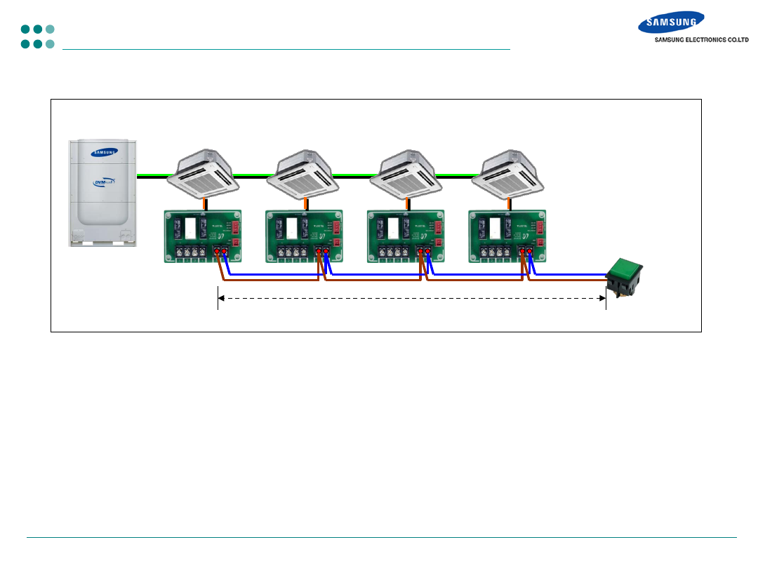
- Contact wiring length
Contact interface module – MIM-B14
Max. 100m
Voltage free
contact
Document Outline
- Slide Number 1
- Slide Number 2
- Slide Number 3
- Slide Number 4
- Slide Number 5
- Slide Number 6
- Slide Number 7
Wyszukiwarka
Podobne podstrony:
HP System Management Homepage Installation Guide (September 2008)
HP System Management Homepage Installation Guide (March 2008)
Groove XR OS53 Operating System Installation and Upgrade Guide 31 Oct 2011
installation guide
Control System Toolbox
10 Emission control system
07 emission control system
04 vpuml installation guide
Kerberos opis systemu i instalacja w OS Linux
10 Engine Control System
systemy instalacyjne TMDIOXUYDTHXS62BO3MEZKBHQ6DP6JA43R6FANQ
install guide
ENGINE CONTROL SYSTEM
Installation Guide
10 Engine Control System
install guide
Core Wall Survey Control System for High Rise Buildings
więcej podobnych podstron