
Telecontrol via a Dial-Up Line
S 40-AM-TD
Application Module
01/99 AWB 27-1300 GB
1st published 1999, edition 01/99
© Moeller GmbH, Bonn
Author:
Thomas Dahmen
Editor:
Klaus Früger, Thomas Kracht
Translators: Mary Allonby-Briggs, Terence Osborn
U1_g.fm Seite 1 Dienstag, 29. Juni 1999 9:41 09

Caution!
Dangerous electrical voltage!
Before commencing the installation
●
Disconnect the power supply of the
device.
●
Ensure that the device cannot be
accidentally restarted.
●
Verify isolation from the supply.
●
Earth and short circuit.
●
Cover or enclose neighbouring units that
are live.
●
Follow the engineering instructions
(AWA) of the device concerned.
●
Only suitably qualified personnel may
work on this device/system.
●
Before installation and before touching
the device ensure that you are free of
electrostatic charge.
●
Connecting cables and signal lines
should be installed so that inductive or
capacitive interference do not impair the
automation functions.
●
Install automation devices and related
operating elements in such a way that
they are well protected against
unintentional operation.
●
Suitable safety hardware and software
measures should be implemented for
the I/O interface so that a line or wire
breakage on the signal side does not
result in undefined states in the
automation devices.
●
Ensure a reliable electrical isolation of
the low voltage for the 24 volt supply.
Only use power supply units complying
with IEC 60 364-4-41 or HD 384.4.41 S2.
●
Deviations of the mains voltage from the
rated value must not exceed the
tolerance limits given in the
specifications, otherwise this may cause
malfunction and dangerous operation.
●
Emergency stop devices complying with
IEC/EN 60 204-1 must be effective in all
operating modes of the automation
devices. Unlatching the emergency-stop
devices must not cause uncontrolled
operation or restart.
●
Devices that are designed for mounting
in housings or control cabinets must only
be operated and controlled after they
have been installed with the housing
closed. Desktop or portable units must
only be operated and controlled in
enclosed housings.
●
Measures should be taken to ensure the
proper restart of programs interrupted
after a voltage dip or failure. This should
not cause dangerous operating states
even for a short time. If necessary,
emergency-stop devices should be
implemented.
IBM is a registered trademark of International
Business Machines Corporation.
All other brand and product names are
trademarks or registered trademarks of the
owner concerned.
All rights reserved, including those of the
translation.
No part of this manual may be reproduced in
any form (printed, photocopy, microfilm or
any otherprocess) or processed, duplicated
or distributed by means of electronic
systems without written permission of
Moeller GmbH, Bonn.
Subject to alterations without notice.

1
01
/99
A
W
B
27-
13
00-
G
B
Contents
Hardware and software requirements
11
Assigning parameters to the data arrays
for telecontrol function blocks
Adapting range limits
in the variable declaration
21

2
01
/99
A
W
B
27-
13
00-
G
B

3
01
/99
A
W
B
27-
13
00-
G
B
About This Manual
This manual describes how to install and how to
assign parameters to the application modules for
telecontrol cards/ modules that communicate with
one another via a dial-up line per EN 60870-5
(IEC 870-5).
Other Manuals (AWBs)
The fundamentals of telecontrol using compact
PLCs are described in a separate manual. Each of
the individual components also has its own manual.
Hardware and Engineering
ZB 4-501-TC1 telecontrol module
AWB 27-1297-GB
Hardware and Engineering
PS 416-TCS-200 telecontrol card
AWB 27-1298-GB
Telecontrol via Leased Line
S 40-AM-TL application module
AWB 27-1301-GB

4
01
/99
A
W
B
27-
13
00-
G
B

5
01
/99
A
W
B
27-
13
00-
G
B
1
General
Field of application
In the controller, function blocks provide the
interface between the telecontrol card/module and
the user program.
The function blocks described are employed if the
telecontrol cards/modules communicate with one
another via dial-up line.
In dial-up line systems, all stations are of equal
status, i.e. each station can establish a connection
with another station via a dial-up modem. Usually,
communication takes place between a controlling
station and several outstations.
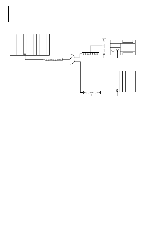
Figure 1 shows the structure of a telecontrol system
using Moeller components that communicate with
one another via dial-up lines.
General
6
01
/99
A
W
B
27-
13
00-
G
B
Figure 1: Telecontrol system communicating via dial-up
line
햲 Controlling station (PS 416 modular controller)
햳 Telecontrol module/card
햴 Outstation (PS 4-200 compact PLC)
햵 Outstation (PS 426 modular PLC)
햶 Dial-up modem
The PS 416 modular controller, plus the PS 416-
TCS-200 telecontrol card acts as the controlling
station. The PS 416-TCS-200 is connected to two
outstations via dial-up modems:
One PS 4-200 compact PLC and ZB 4-501-TC1
telecontrol module,
Another PS 416 modular controller and the
PS 416-TCS-200 telecontrol card.
PS 416-CPU
PS 416-T
C
S-200
PS 416-T
CS-200
PS 4-200
ZB 4-501-TC1
PS 416
PS 416
햲
햳
햶
햶
햴
햵
햳
햶
햳
PS 416-CPU
Field of application
7
01
/99
A
W
B
27-
13
00-
G
B
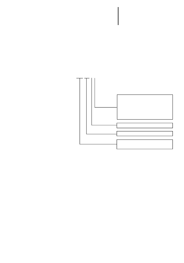
Key to the Type Reference for Function Blocks
Function blocks are available to the user for data
transmission via dial-up line.
The function blocks offer the user many
transmission services by means of which even
complex projects can be set up unproblematically.
Figure 2: Key to the Type Reference for Function Blocks
S 4 0 T 1_U 0
S 4 – PS 4-150/200/300
S 40 – PS 416
Version 0 for 1 station
Version 1 for 2 stations
Version 2 for 4 stations
Version 3 for 8 stations
Version 4 for 16 stations
Version 5 for 32 stations
Version U – universal function block
Type 1- Dial-up line

General
8
01
/99
A
W
B
27-
13
00-
G
B
Application module S40-AM-TD contains the
function blocks listed in Table 1. In addition to the
telecontrol function blocks for PS 4/PS 416,
selectable function blocks for modems will be
available for use in the application module.
Table 1: Function blocks of the S40-AM-TD application
module
Controller Description FB
PS 4-150/200/300 1 configurable station
S4T1_U0
2 configurable stations
S4T1_U1
4 configurable stations
S4T1_U2
8 configurable stations
S4T1_U3
16 configurable stations
S4T1_U4
PS 416 1 configurable station S40T1_U0
2 configurable stations
S40T1_U1
4 configurable stations
S40T1_U2
8 configurable stations
S40T1_U3
16 configurable stations r S40T1_U4
32 configurable stations
S40T1_U5
Call function block (FB) Universal-Modem TCD_UNI
Modem LGH 28.8 (ke) TCD_KE28
Modem LGH 64K (ke) TCD_KE64
Modem Loges 64K/M TCD_KE64
Modem TD-32DC (westermo) TCD_WE32

Hardware and software
requirements
9
01
/99
A
W
B
27-
13
00-
G
B
Hardware and software
requirements
Table 2 gives an overview of the hardware and
software requirements for use of call function
blocks.
Table 2: Hardware and Software Requirements
Installation
왘 Copy the function blocks for the application
module to the “KOMPO.SYS” directory for your
project.
왘 Use the “Edit 씮 Register sources” menu option
to register your function blocks in the Project
Manager .
왘 Open and save the requisite function blocks.
You can then employ these function blocks as user-
specific function blocks when editing your program.
Please note that the function blocks must be called
up for each cycle of your user program.
Function
block
S4T1_xx
S40T1_xx
Software
Sucosoft S 40 from Version 3.01 onwards
Sucosoft S 40 from Version 3.01 onwards
Hardware
Central controller PS 4 – 150/200/300
Telecontrol card ZB 4-501-TC1
Version 2.0
Memory expansion ZB 4-032-SR1 or
ZB 4-160-SM1
Telecontrol module PS 416-TCS-200
Version 2.0
PS 416-CPU-200/300/400 with operating
system
from Version 2.0 onwards
Optional RAM PS 416-MEM-430 or PS 416-
MEM-431 memory card
)
You must initialise the westermo TD-32DC
modem prior to connection to the telecontrol
modules via a terminal program, e.g. Windows
hyperterminal, using the following parameters:
AT&F&C1&K0&Y0S0=01X3&W0

General
10
01
/99
A
W
B
27-
13
00-
G
B
Program type entries into the POU variable
declaration
If you wish to edit the S4T1_Ux telecontrol function
block for the PS 4 compact controller in the user
program, you must input data into the variable
declaration.
Enter the following data in the “program” type POU
variable declaration:
VAR_GLOBAL
TC1_rdata AT %RDB1.1.0.0 : ARRAY [1..36] OF BYTE ;
TC1_tdata AT %SDB1.1.0.0 : ARRAY [1..36] OF BYTE ;
END_VAR
11
01
/99
A
W
B
27-
13
00-
G
B
2
Data Arrays
Data is exchanged betweeen stations via “byte”
type data arrays. This means that data formatted
differently in the application require conversion prior
to entry in the data array. Conversely, array
elements must be converted to the data format of
the application before they can be read.
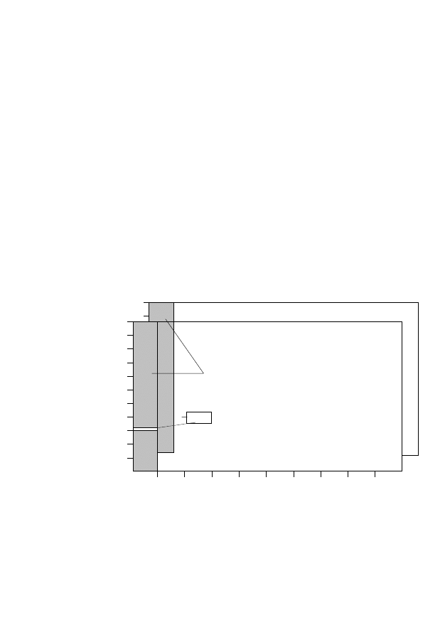
Organisation
Within the function block, data arrays are defined in
the variable declaration. Each outstation requires
one data array for the receive data and one for the
send data.
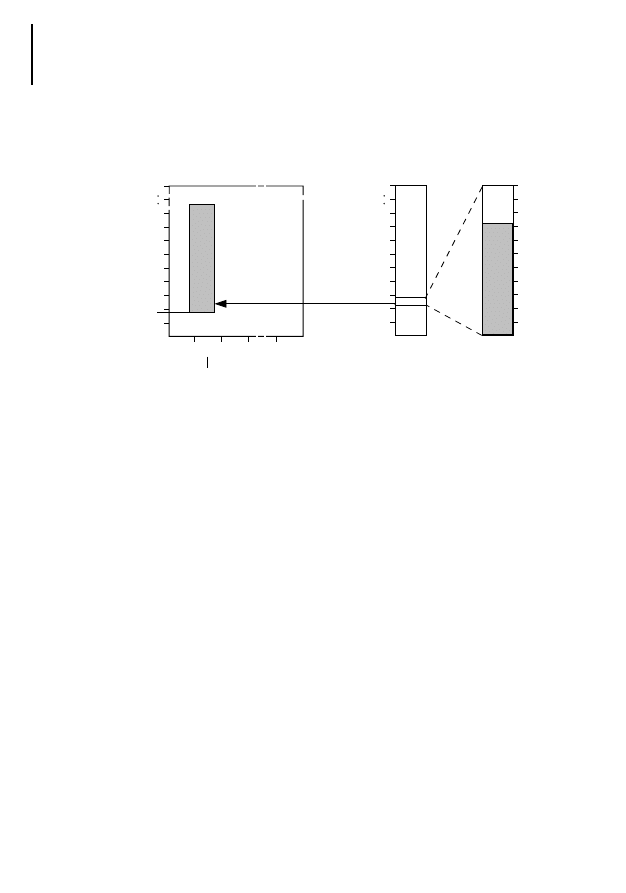
Figure 3: Structure of the send and receive data array of
an outstation in the telecontrol function block
2
0
1
3
4
5
6
7
. . .
255
10
20
30
40
50
60
70
80
90
219
0
.
.
30
219
255
Offset address
Send data array
Receive data array
Data area for fixed length frames
(In fixed length frames, the offset is always 0)
byte
Subaddress

Data Arrays
12
01
/99
A
W
B
27-
13
00-
G
B
The subaddress
Specifies the number of available offset address
ranges.
The offset address
Specifies the maximum number of bytes within a
subaddress.
The maximum definable size of each data array in
the controlling station is approx. 6.5 kbytes (PS 4-
150/200) and approx. 13 kbytes (PS 4-300/PS 416)
for send and receive data arrays together. This
available range must be distributed equally to all
outstations in the telecontrol line.
It is possible to assign different settings tosend and
receive arrays. Please make sure that the size of the
controlling station send data array matches the size
of the outstation receive data array and vice-versa.
When using a PS 416 or PS 4-300 controller as the
controlling station, calculate the maximum available
quantity of data (send and receive data arrays) per
outstation as follows:
When assigning offset addresses and
subaddresses, make sure that the maximum
available quantity of data is not exceeded.
Offset addresses x subaddresses (send data array)
+ offset addresses x subaddresses (receive data array)
= quantity of data <=maximum data quantity per outstation
Maximum quantity of data per outstation
13000 bytes
Number of outstations in the telecontrol line
---------------------------------------------------------------------------------------------------------------------
=

Assigning parameters to
the data arrays for
telecontrol function blocks
13
01
/99
A
W
B
27-
13
00-
G
B
Assigning parameters
to the data arrays for
telecontrol function
blocks
Telecontrol function blocks are supplied with a
parameter set based on a 20 byte data transmission
in send and receive modes.
Data arrays in the variable declaration of the
function blocks come complete with a ready-
assigned set of parameters. However, the
parameters need to be adapted accordingly if the
default parameters do not conform to requirements.
Function blocks have the following data array-
related basic settings and range limits.
VAR_INPUT
requested_station : USINT
(1..x) ;
Number of partner stations
tra_dat: ARRAY
[1..x, 0..0, 0..19] OF BYTE ;
Send data array (x = station number
according to the function block,
subaddresses and offset addresses
selected).
END_VAR
VAR_OUTPUT
rec_dat: ARRAY
[1..x, 0..0, 0..19] OF BYTE ;
Receive data array (x = number of
stations according to the function block
selected), subaddresses, offset
addresses.
END_VAR
VAR_CONSTANT
tra_dfl_max: USINT:
20;
Limit on the maximum length of data
array in “send” mode
rec_dfl_max: USINT:
20;
Limit on the maximum length of data
array in “receive” mode.
tra_sub_max: USINT:
0 ;
Maximum subaddress in “send” mode
rec_sub_max: USINT:
0 ;
Maximum subaddress in “receive”
mode
END_VAR

Data Arrays
14
01
/99
A
W
B
27-
13
00-
G
B
Identical
fixed_length
entries must be selected within
a telecontrol line (controlling station plus all
outstations).
Adapting range limits
in the variable
declaration
If the function blocks have not yet been
incorporated in their S 40 software, start by reading
the “Installation” chapter on page 9 and then read
on from this point.
When setting the range limits, be sure to observe
the following rules:
Variables:
requested_station
The lower range limit for variables must always be 1.
The upper range limit for variables determines the
maximum number of planned outstations.
Constants)
tra_dfl_max
For the tra_dfl_max constant, the maximum number
of offset addresses must be specified for the
tra_dat
send data array.
Rec_dfl_max
For the Rec_dfl_max constant, the maximum
number of offset addresses must be specified for
the
rec_dat
receive data field.
Tra_sub_max
For the Tra_sub_max constant, the highest value of
the valid sub-adresses must be input for the
tra_dat
send data array.
Rec_sub_max
For the Rec_sub_max constant, the highest value of
valid subaddresses must be input for the
rec_dat
receive data array.

Adapting range limits in the
variable declaration
15
01
/99
A
W
B
27-
13
00-
G
B
Arrays (Controlling station:)
tra_dat, rec_dat
Established by the range limits of the
requested_station variables and the tra_dfl_max,
rec_dfl_max, tra_sub_max and rec_sub_max.
constants.
Send data array
tra_dat(1..(Anzahl Teilnehmer),0..(tra_sub_max),
0..((tra_dfl_max)-1)
Receive data array
rec_dat(1..(Anzahl Teilnehmer),0..(rec_sub_max),
0..((rec_dfl_max)-1)
Save the function block under another name.
Change the desired parameters in the variable
declaration.
Check your changes by checking syntax using
(ALT+F10).
The modified function block is retained for further
use in the list of user-defined function blocks.
Example
Two outstations are connected to the controlling
station via dial-up modem. The outstations
communicate solely with the controlling station. The
controlling station sends 5 bytes to the outstations
and receives 30 bytes from the outstations. This is
achieved by setting the following parameters in the
variable declarations of the controlling and
outstations:
Controlling Station
Block S40T1_U1 is used for the controlling station.
The above-mentioned parameters generate a 70
byte data memory requirement.

Data Arrays
16
01
/99
A
W
B
27-
13
00-
G
B
VAR_INPUT
requested_station : USINT
(1..2) ;
tra_dat: ARRAY
[1..2, 0..0, 0..4] OF BYTE ;
(*send data array (station number,
subaddresses, offset addresses)*)
END_VAR
VAR_OUTPUT
rec_dat: ARRAY
[1..2, 0..0, 0..29] OF BYTE ;
(*Receive data array (station number
subaddresses, offset addresses)*)
END_VAR
VAR_CONSTANT
tra_sub_max : USINT:0;
rec_sub_max : USINT:0;
tra_dfl_max : USINT:5;
rec_dfl_max : USINT:30;
END_VAR
Outstation
Block S4T1_U0 is used for the outstations. The
above-mentioned parameters generate a 35 byte
memory requirement. The following array definitions
and range limits must be used in the variable
declaration:
VAR_INPUT
requested_station : USINT
(1..1) ;
tra_dat: ARRAY
[1..1, 0..0, 0..29] OF BYTE ; (*Send data array (station number,
subaddresses, offset addresses)*)
END_VAR
VAR_OUTPUT
rec_dat: ARRAY
[1..1, 0..0, 0..4] OF BYTE ; (*Receive data array (station number,
subaddresses, offset addresses)*)
END_VAR
VAR_CONSTANT
tra_sub_max : USINT:0;
rec_sub_max : USINT:0;
tra_dfl_max : USINT:30;
rec_dfl_max : USINT:5;
END_VAR

Working with data arrays
17
01
/99
A
W
B
27-
13
00-
G
B
Working with data
arrays
The next section describes how to read or write data
arrays taking the send or receive data arrays of a
controlling station as the example.
Ensure that all the array indices are within range
limits when accessing data arrays. If the array index
limits are outside range limits, the controller will
HALT and the NOT READY-LED will light up.
In the variable declaration of the function block, the
data arrays have been defined as follows:
VAR_INPUT
tra_dat: ARRAY
[1..2, 0..0, 0..29] OF BYTE ;
(*Send data array (station number,
subaddresses, offset addresses)*)
END_VAR
VAR_OUTPUT
rec_dat: ARRAY
[1..2, 0..0, 0..4] OF BYTE ;
(*Receive data array (station number
subaddresses, offset addresses)*)
END_VAR
Writing data array elements
The 5 constant should be saved in the 2 station,
subaddress 0, offset address 3 array element.
LD 5
ST Instance_name.tra_dat
[2,0,3]
.
.
END_PROGRAM
Reading data array elements
The content of the 2 station, subaddress 0 and
offset address 3 array element of the receive data
array is stored under the
VALUE_1
variable.

Data Arrays
18
01
/99
A
W
B
27-
13
00-
G
B
VAR
VALUE_1 : USINT ;
END_VAR
.
.
LD
Instance_name.rec_dat
[2,0,3]
BYTE_TO_USINT
ST
WERT_1
.
.
END_PROGRAM
Accessing data arrays with fixed-length frames
When data is transmitted using fixed length frames,
only the data array range for subaddress 0 is
defined. The data is read and written starting with
tra_source_offset:=0
up to length specified under the
fixed_length
parameter.
Accessing data arrays with variable-length
frames
All the elements of the data array can be accessed
using variable-length data frames. The
tra_subaddress,
tra_source_offset
and/or
tra-destination_offset
function
block inputs and
tra_variable_length
user data length
can be used to access from one byte up to the
entire data array length of a subaddress.
User_status bits
User_status bits are used to transfer up to four bits
of information and are relayed from the passive
station to the active station. . If status changes are
detected at the
user_status_1
to
user_status_4
FB inputs
of the outstation while a service is being processed,
the inputs will be automatically updated in the array
of user_status bits at the active station.
Working with data arrays
19
01
/99
A
W
B
27-
13
00-
G
B
User_status bits are suitable for transferring bits
such as battery monitoring (DBM) without the need
for a separate service to the partner station.
Active station
Passive station_1
User_status
_1
_2
_3
_4
_1
_2
_3
_4
Outstation_1
Outstation_2
Passive station_2
Outstation_n

20
01
/99
A
W
B
27-
13
00-
G
B

21
01
/99
A
W
B
27-
13
00-
G
B
3
Function Blocks
Function blocks form the link between the user
program and the card/module.
The S 40-AM-TD application module provides both
the telecontrol function blocks and call function
blocks required. . Function blocks are functional
only when used in combination. Error-free
communication requires respectively one call
function block –depending upon the modem
employed and one telecontrol function block –
depending upon the number of configurable
stations.
Call function blocks
Call function blocks undertake the following
functions: modem initialisation
Connection establishment/clearance to the
partner station
Connection monitoring
Recall within the defined timing frame
Modem communication display
The scope of the supply includes several call
function blocks for modems tested and
recommended by Moeller. These function blocks
come with parameters already assigned to the
initialisation string thereby dispensing with the need
for any further modem-specific adjustments
(universal modem excepted). The universal modem
function block is used if a modem other than the
specified modem is employed or if changes need to
be made to the initialisation string.

Function Blocks
22
01
/99
A
W
B
27-
13
00-
G
B
The modem must satisfy the following requirements:
Direct mode (no data compression, no correction
process)
8E1 data format
RTS, CTS, DTR, DSR, DCD control lines
Table 3: Type of call function block depending on the
modem used
Tabelle 4: Interface of the call function blocks
)
If you want to use the universal modem function
block, first of all read the section on “Modem
codes” on page 28.
Modem
Manufacturer
Call function block
Universal-Modem
any
TCD_UNI
LGH 28.8
ke Kommunikations Elektronik
TCD_KE28
LGH 64K
ke Kommunikations Elektronik
TCD_KE64
LOGES64K/M
ke Kommunikations Elektronik
TCD_KE64
TD-32DC
westermo
TCD_WE32
Call function block
Input/output
TCD_KExx
TCD_WExx
TCD_UNI
reset :=,
҂
҂
lock_station :=,
҂
҂
dial :=,
҂
҂
dial_repeat :=,
҂
҂
dial_wait_repeat:=,
҂
҂
dial_timeout :=,
҂
҂
dial_praefix :=,
҂
҂
dat_format:=,
–
҂
cmd_format:=,
–
҂
telegramformat :=,
҂
҂
baudrate :=,
҂
҂
slotnumber:=,
҂
҂

Call function blocks
23
01
/99
A
W
B
27-
13
00-
G
B
Call function block inputs
Table 5 shows all of the function block inputs that
are liable to be encountered with individual types of
call function blocks.
Tabelle 5: Call function block inputs
init_string:=,
–
҂
modem_response :=,
҂
҂
modem_notify,
҂
҂
|
:=active,
҂
҂
:=result
҂
҂
:=dcd,
҂
҂
:=alarm,
҂
҂
:=modem_request,
҂
҂
:=modem_control,
҂
҂
:=message,
҂
҂
:=wait_time,
҂
҂
:=modem_code,
҂
҂
:=fail_code,
҂
҂
Call function block
Input/output
TCD_KExx
TCD_WExx
TCD_UNI
Designation
Data type
Value range
Description
reset
BOOL
0/1
Put the call and relevant telecontrol function block
in basic mode and initialise the modem.
lock_station
BOOL
0/1
Lock_station: =1 locks the station against any
services from other stations (except for service 33).
If the station is locked, error code 4B will be
displayed.
dial
BOOL
0/1
Activation of the dial input establishes a connection
to the predetermined partner station. The
connection is cleared once dial has been
deactivated.

Function Blocks
24
01
/99
A
W
B
27-
13
00-
G
B
dial_repeat
UINT
Number of dial repeats, if no connection could be
established. If the dial-repeat entry is set to “0”,
then alarm is activated only if the function block
output registers a 2F error code.
dial_wait_repeat
TIME
T#0s
T#30s – T#60min
Waiting time between dial repeats. After each abor-
tive attempt, the time is doubled, the maximum
length of time being, however, 60 minutes. After a
successful attempt, the time is reset to the specified
value. The minimum waiting time must be 30
seconds (country-specific value).
If the entry is not given a time parameter, this
function is deactivated.
dial_timeout
TIME
Maximum bus idle time.
If no data traffic is taking place for the specified
time, the connection is severed once this time has
elapsed. If the input is not accompanied by a
specified time value, this function I deactivated.
dial_praefix
STRING
max.
10 characters
For the modem call prefix, see also table 8 on
page 27.
dat_format
STRING
8N1,8N2,8E1,8O1 Character format in data mode.
cmd_format
STRING
8N1,8N2,8E1,8O1 Character format in command mode.
telegramformat
BOOL
0/1
Selection of telecontrol frame format
0: FT1.2
1: FT3
baudrate
UINT
->
Baud rate: 2400, 4800, 9600, 19200; the 19200
Bd baud rate is not suitable for the TD-32DC
modem.
slotnumber
USINT
4 – 20
Slot number of the installed PS 416-TCS-200.
init_string
STRING
max.
90 characters
For the modem initialisation string, see also table 7
on page 26.
modem_response
STRING
–
Communications buffer for the telecontrol function
block. This input must be linked with the
modem_response
output of the telecontrol function
block.
modem_notify
ARRAY OF
BYTE
–
Communications buffer for the telecontrol function
block. This input must be linked with the
modem_notify output of the telecontrol function
block.
Designation
Data type
Value range
Description

Call function blocks
25
01
/99
A
W
B
27-
13
00-
G
B
Call function block outputs
Table 6 shows all of the function block outputs liable
to occur with individual types of call function blocks.
Table 6: Call function block outputs
Designation
Data type
Description
active
BOOL
Indicates that the connection is being established to the specified
station.
result
BOOL
If the connection has been made successfully,
result
is registered.
If connection has been unsuccessful, no
result
is displayed.
result
is activated by a falling edge at the output.
dcd
BOOL
Connection is established.
alarm
BOOL
Output is achieved if, after the specified number of attempts has
failed to establish a connection. If the
dial_repeat
input is set to
“0”, alarm is triggered only if function block output has an H2F error
code.
modem_request
STRING
Communication buffer for the telecontrol function block. You must
link this output with the
modem_request
input of the telecontrol
function block.
modem_control
ARRAY OF BYTE
Communication buffer for the telecontrol function block. You must
link this output with the
modem_control
input of the telecontrol
function block.
message
STRING
For plain text status reports, see also table 9 on page 27.
wait_time
TIME
Time pending the next attempt at connection.
modem_code
USINT
Modem numerical data displays. To discover what the digits means,
refer to the manual for the modem used. The call function blocks
generate an additional five modem signals of their own.
251:
Incoming call is being processed (ring detected)
252:
Partner station clears connection (BREAK)
253:
Local disconnection (DISCONNECT)
254:
Connection broken after
dial_timeout
bus idle time expiry
(CUT LINE)
255:
Active code during initialisation or dial-up phase (DIAL. INIT.)
fail_code
USINT
Error codes, see table 15 on page 53

Function Blocks
26
01
/99
A
W
B
27-
13
00-
G
B
Initialisation string
Modem parameters are adapted to the telecontrol
application by sending an initialisation string to the
modem after switching on the controller or after a
RESET.
For the universal modem function block TCD_UNI,
you must apply the initialisation string to the
init_string
FB input.
The initialisation strings for the function blocks of
the recommended modems come ready installed –
see table 7. The transfer process is selected
according to the set baud rate.
Table 7: Initialisation string settings of the function blocks
for the recommended modems
Description
Modem parameter
Modem
LGH 28.8D1
LGH 64K
Loges64K/M
TD-32DC
Transfer process
2400 Bd
V.22
4800 Bd
V.32
9600 Bd
V.32
19200 Bd
V.34
F3
F21
F23
F48
F3
F21
F23
F48
F5
F6
F8
–
Direct mode
N1
N1
N1
Echo off
E0
E0
E0
Output signal code
Q0
Q0
Q0
Signal code numerically
V0
V0
V0
Signal code expanded
X3
X3
X3
M5/109 control and signal line
&C2
&C2
&C1
DSR Option (DSR is always ON)
&S0
&S0
&S0
When an ON-OFF pulse is received at S1,
the connection is broken
&D2
&D2
&D2
Number of call characters
S0=1
S0=1
S0=1
Carrier recognition time
S7=20
S7=20
S7=20
Data format in the 8E1 data transfer phase
S60=2
S60=2
–
Compatibility to LGH28.8
–
S47=2
–

Call function blocks
27
01
/99
A
W
B
27-
13
00-
G
B
Dial-up prefix
The dial-up procedure is defined by the dial_prefix
function block input. Check the general specification
for the telephone exchange or network. Also, read
about this aspect in your modem manual.
Table 8: Call prefix settings
ATD
Connection configured with dial-up
character sequence
P
Pulse dial
T
Tone dial
*
Special tone dial character (analog counterpart
in the case of the Loges 64K/M modem)
0
Subscriber line request obtain dial tone,
(important for PABX)
W
Waiting for dial tone recognition
,
dial interval
Function block output
message
Whilst the telecontrol block is communicating with
the modem, the modem generates status messages
which are displayed on the FB output
message
as plain
text and on the FB-output
modem_code
as a numerical
value.
Table 9: Plain text messages on the FB output message
1
2
3
4
ATD
P
0
w
T
*
xx
_
i
_
Modem status report
message
Meaning
OK
Correct input
RING
Incoming call
NO_CARRIER
No or excessively low signal reception level

Function Blocks
28
01
/99
A
W
B
27-
13
00-
G
B
Modem codes
The modem uses the modem codes to inform the
telecontrol block about modem status. The codes
are evaluated in the call function block.
Codes 0 to 10 usually have the same meaning even
if the modems are from different manufacturers.
Modem codes above the value of 10, on the other
hand, differ from one modem manufacturer to
another.
ERROR
Input error
NO_DIALTON
No dial tone or loop current available
BUSY
Busy tone received
NO_ANSWER
No reply tone received
ABORT
Abort
BLACK_LISTED
Auto-dial blocked (see modem manual).
DELAYED_CALL
Delayed call (see modem manual)
CONNECT
Xxxxbd data connection
DISCONNECT
Local disconnect
CUT_LINE
Connection cleared after timeout
DIAL
Active code during the dial-up phase
SEND INIT
Modem initialisation.
GET NUMBER
Loading of telephone number from telecontrol function block.
RESET
The
reset
FB input is activated. The telecontrol and call function block are reset
and the modem is initialised.
NO COM_REF_VALUE
No communication reference is available for the selected station.
NO DIALNUMBER
No telephone number is available for the selected station.
TC ERROR
Communication error between modem, telecontrol and call function block.
ANY MESSAGE
The modem emits a code (FB output
modem_code
) unknown to the call function
block and cannot be converted into a plain text message
Modem status report
message
Meaning

Telecontrol function blocks
29
01
/99
A
W
B
27-
13
00-
G
B
In the universal call function block TCD_UNI, the
initialisations listed below are located in the variable
declaration. If you use the universal function block,
you must adapt your modem codes to these
settings. Where appropriate, adjust your modem
accordingly.
Var constant
mo_ok
: USINT:=
0 ; (*“O.K.” message *)
mo_ring
: USINT:=
2 ; (*“RING” message *)
mo_no_carrier
: USINT:=
3 ; (*“NO_CARRIER” message *)
mo_error
: USINT:=
4 ; (*“ERROR” message *)
mo_no_dialton
: USINT:=
6 ; (*“NO_DIALTON” message *)
mo_busy
: USINT:=
7 ; (*“BUSY” message *)
mo_no_answer
: USINT:=
8 ; (*“NO_ANSWER” message *)
mo_abort
: USINT:=
15 ; (*“ABORT” message *)
mo_blacklisted
: USINT:=
26 ; (*“BLACKLISTED” message *)
mo_delayed_call
: USINT:=
27 ; (*“DELAYED_CALL” message *)
mo_connect_1
: USINT:=
1 ; (*“CONNECT” message *)
mo_connect_2
: USINT:=
5 ; (*“CONNECT_1200” message *)
mo_connect_3
: USINT:=
10 ; (*“CONNECT_2400” message *)
mo_connect_min
: USINT:=
30 ; (*“Lowest value of the
CONNECT message area“ *)
mo_connect_max
: USINT:=
79 ; (*”Highest value of the
CONNECT message area“ *)
End_Var
These entries in the variable declaration are not
available for the call function blocks for modems
tested and recommended by Moeller.
Telecontrol function
blocks
The telecontrol function blocks are responsible for
the following functions:
Evaluating the station address of a receive frame
Monitoring the timeout of a service
Generating interface services and/or
communications services
Modem communication

Function Blocks
30
01
/99
A
W
B
27-
13
00-
G
B
Function blocks differ according to the controller
used and the number of responding stations.
Table 10: Available function blocks
PS 4-150/200/300
plus ZB 4-501-TC1
PS 416 plus
PS 416-TCS-200
Maximum number of
responding stations
Telecontrol function blocks
1
S4T1_U0
S40T1_U0
2
S4T1_U1
S40T1_U1
4
S4T1_U2
S40T1_U2
8
S4T1_U3
S40T1_U3
16
S4T1_U4
S40T1_U4
32
–
S40T1_U5

Telecontrol function blocks
31
01
/99
A
W
B
27-
13
00-
G
B
Telecontrol function block inputs
Table 11 describes all of the function block inputs.
Table 11: Telecontrol function block inputs
Input
Data
type
Value
range
Description
strobe
BOOL
0/1
Start of the service associated with the command.
Active only when ready =1
station_type
BOOL
0/1
Station type
0: type B (all services available up to service 30)
1: type A (all services available)
requested_station
USINT
1 – x
Partner station with which the connection is to be
made.
The upper value limit depends on the telecontrol
function block selected.
command
USINT
10 – 33
For the command code for the services offered, see
table 13 on page 35.
lock_data
BOOL
0/1
Lock_data
:=1 means that writing of the data array
is disabled.
lock_time
BOOL
0/1
Lock_time
:=1 means that time synchronisation is
disabled.
lock_flash
BOOL
0/1
Lock_flash
:=1 means that writing of the flash is
disabled or is not available.
tel_repeat
USINT
0..255
Number of frame repeats in the event of a protocol
error
time_adjust
UINT
0..59
Time correction value in seconds for synchronising
the PLC clock
The value is added to the clock time value received.
It must be determined as a function of baud rate
and signal transit time. (0-59 value range)
fixed_length
USINT
–
Data length for fixed length frames
user_status_1
BOOL
0/1
User status bit 1
user_status_2
BOOL
0/1
User status bit 2
user_status_3
BOOL
0/1
User status bit 3
user_status_4
BOOL
0/1
User status bit 4

Function Blocks
32
01
/99
A
W
B
27-
13
00-
G
B
tra_status
WORD
0 – 65535
Status word
The status word is relayed automatically between
stations after each connection has been made and
upon completion of service 31.
(It is indicated in the status array of the partner
station).
tra_variable_length
USINT
–
Data length in the case of variable length frames.
tra_subaddress
USINT
0 – 255
Definition of the subaddress for variable length
frames
tra_source_offset
USINT
0 – 219
Source offset address in the case of variable length
frames
tra_destination_offset
USINT
0 – 219
Target offset address in the case of variable length
frames
tra_flash_segment
UINT
0 – 511
Segment number of the flash memory and/or RAM
memory card in the partner station.
Over 512 segments can be called up with the RAM
memory card (see also page 38 und page 41).
tra_dat
ARRAY
OF BYTE
Send data array
com_ref_1
UINT
1 – 65534
Communication reference 1
com_ref_2
UINT
1 – 65534
Communication reference 2
com_ref_n
UINT
1 – 65534
Communication reference n
phone_number_1
STRING
32 characters
Telephone number of 1
st
partner station
phone_number_2
STRING
32 characters
Telephone number of 2
nd
partner station
phone_number_n
STRING
32 characters
Telephone number of n
th
partner station
tra_information
STRING
32 characters
Text string for transmission; relayed upon
implementation of service 33.
modem_request
STRING
50 characters
Communications buffer for the call function block.
You must combine this input with the
modem_request
output of the call function block.
modem_control
ARRAY
OF BYTE
–
Communications buffer for the call function block.
You must combine this input with the
modem_control
output of the call function block.
Input
Data
type
Value
range
Description

Telecontrol function blocks
33
01
/99
A
W
B
27-
13
00-
G
B
Telecontrol function block outputs
Table 12 describes all function block outputs.
Table 12: Telecontrol function block outputs
Output
Data
type
Description
ready
BOOL
Once the output is live, the connection is made and the telecontrol
function block is ready to perform services.
tra_active
BOOL
Indicates that a service, initiated by the station itself, is being
provided. If command processing is terminated, this signal reverts to
0.
tra_result
BOOL
Tra_result
is updated after a falling edge on the
tra_active
output.
A
tra_result =0
denotes that there has been an error in executing
the service.
tra_fail
BOOL
An error indicated at a station that has activated a service. It is
updated with every falling edge of the
tra_active
output.
rec_active
BOOL
Indicates the processing of a service. If command processing is
terminated, then this signal reverts to 0.
rec_result
BOOL
Rec_result
is updated after a falling edge on the
rec_active
output.
A
rec_result =0
means that an error has occurred during execution
of a service.
rec_fail
BOOL
An error indicated at a station that has received a service. It is
updated whenever there is a falling edge on the
rec_active
output.
rec_length
UINT
Number of data bytes in a data frame activated by the partner station.
rec_subaddress
UINT
Subaddress in a data frame activated by the partner station.
rec_offset
UINT
Offsetaddress in a data frame activated by the partner station.
rec_flash_segment
UINT
Segment number of the flash memory and/or the RAM memory card
to which the partner station has access.
rec_action
UINT
Code of the service received activated by the partner station.
rec_com_ref
UINT
Communication reference for which a frame has been input.
rec_information
STRING
Received text string relayed using service 33 by the partner station.

Function Blocks
34
01
/99
A
W
B
27-
13
00-
G
B
1)
Updated after services 20 and 21 executed.
2)
Updated with connection establishment and after service 31 "Read Status"
executed.
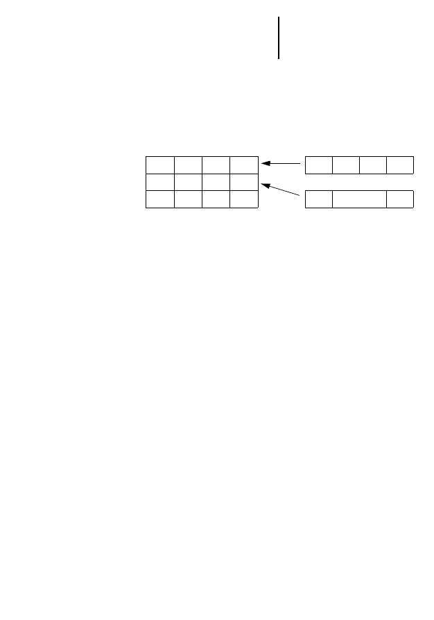
user_status
ARRAY
Two-dimensional user status bit ARRAY
(
user_status
(
Station_n
,
user_status_n
))
user_status_ 1 2 3 4
_________
Station_1 | | | | |
---------
Station_2 | | | | |
---------
Station_n | | | | |
---------
rec_clock
1)
DT
Partner station clock
rec_status_array
2)
ARRAY
OF WORD
[0]:
tra_status
value
[1]:
fixed_length
parameter
[2]
dial_repeat
parameter
[3]:
dial_timeout
parameter
[4]:
dial_wait
parameter
[5]:
Transmit frame counter
[6]:
Receive frame counter
[7]:
Protocol error counter
[8]:
Frame error counter
[9]:
Local error counter
[10]: Other error counter
[11]: Dial-up repeats
[12]: Successful communications connections counter
[13]: Alarm counter
com_ref_value
UINT
Current communications reference value
rec_dat
ARRAY
OF BYTE
Receive data array
fail_code
USINT
In the event of errors, where
tra_result =0
or
rec_result =0
, the
error code will be indicated under
fail_code
. The output is updated
with every falling edge of the
tra_active
or
rec_active
outputs.
modem_response
STRING
Communication buffer for the call function block.
You must combine this output with the
modem_response
input of the
call function block.
modem_notify
ARRAY
OF BYTE
Communication buffer for the call function block.
You must combine this output with the
modem_notify
input of the call
function block.
Output
Data
type
Description

Services
35
01
/99
A
W
B
27-
13
00-
G
B
Services
After the connection has been made between
stations via the call function block, the telecontrol
function blocks make data exchange services
available between individual telecontrol stations.
They are activated by relaying the corresponding
code to the command input of the function block
and via a signal at the strobe input.
Table 13: Overview: Services obtainable from the
telecontrol blocks
Function group
Designation
Code
Variable access
services
RAM send data fixed
frame length
10
RAM send data variable
frame length
12
FLASH/RAM memory card
send data variable frame length
13
RAM read data
variable frame length
15
FLASH/RAM memory card read data
variable frame length
16
RAM send/read data
fixed frame length
17
Support services
Read programmable controller clock –
partner station
20
Synchronising the programmable
controller clock – partner station
21
Remote control
Remote reset
30
Read status
31
Send information string
33
Function Blocks
36
01
/99
A
W
B
27-
13
00-
G
B
Service 10: Send data fixed frame length RAM
When calling up this service using a fixed length
frame, fixed length-data bytes from the RAM send
requested_station data array are transferred from
Station A to the RAM receive data array of station B.
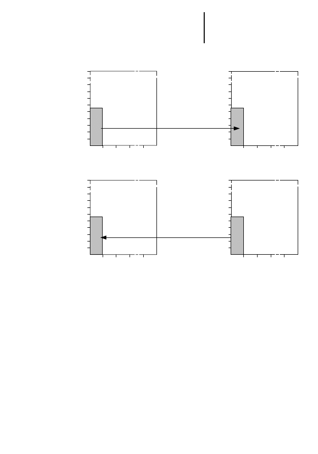
Figure 4: Service 10: RAM send data fixed frame length
The
fixed_length
parameter must be identical in all
stations using the service.
Subaddress
RAM send data array
Station A
Subaddress
Offset
address
RAM receive data array
Station B
Offset
address
2
0
1
. . . 255
10
30
40
50
60
70
80
90
219
0
.
.
2
0
1
. . . 255
10
20
40
50
60
70
80
90
219
0
.
.
30
20
fixed_length
Services
37
01
/99
A
W
B
27-
13
00-
G
B
Service 12: Send data variable frame length RAM
From the RAM send requested_station data array of
the controlling station, a data segment (specified by
the subaddress
tra_subaddress
, offset
tra_source_offset
and data frame length
tra_variable_length
) is sent to
the receive data array of the outstation, where the
data segment is stored in the receive data array with
the coordinates
tra_subaddress
(
rec_subaddress
) and
tra_destination_offset
(
rec_offset
)
Figure 5: Service 12: RAM send data variable frame length
Subaddress
RAM receive data array
Station A
Subaddress
Offset
address
RAM send data array
Station B
Offset
address
tra_subaddress
tra_
source_offset
tra_destination_
offset
2
0
1
. . . 255
10
30
40
50
60
70
80
90
219
0
2
0
1
. . . 255
20
40
50
60
70
80
90
219
0
30
tra_variable_
length

Function Blocks
38
01
/99
A
W
B
27-
13
00-
G
B
Service 13: FLASH/RAM Memory card send data
variable frame length
A data segment (specified by
tra_subaddress
,
tra_source_offset
and
tra_variable_length
) from the RAM
requested_station
send data array of station A is sent
into the
tra_flash_segment
of the Flash memory (PS 4)
or RAM memory card (PS 416) of station B.
If station B is a PS 416 controller, the number of
segments is adjustable. The standard arrangement
in the user module consists of 512 segments. If you
wish to change the number of available segments
on the memory card, refer to the section entitled
“Function block SetMCFileLength” of the manual
“S 40 Language Elements for PS 4-150/ -200/-300
and PS 416” (AWB 2700-1306 GB).
If you change the number of available segments,
you must alter the range limit for FB input
tra_flash_segment in the variables declaration for
the function block.
VAR_INPUT
flash_segment : UINT(
0..511) ;(*Adapt the number
of segments)
END_VAR
See also “Adapting range limits in the variable
declaration” on page 14.
)
If station B is a PS 4-300 controller, format the
memory card with a recipe area.
Services
39
01
/99
A
W
B
27-
13
00-
G
B
Figure 6: Service 13: FLASH/RAM memory card send data
variable frame length
tra_subaddress
tra_
source_offset
2
0
1
. . . 255
10
30
40
50
60
70
80
90
219
0
20
40
50
60
70
80
90
511
0
30
tra_variable_
length
tra_flash_segment
0
127
10
Flash memory (PS 4)
RAM Memory Card (PS 416)
(512 Segmente at 128 Byte)
Subaddress
Station A
Segment
number
RAM send data array
Station B
Offset
address
Function Blocks
40
01
/99
A
W
B
27-
13
00-
G
B
Service 15: RAM read data variable frame length
A data segment (specified by subaddresses
tra_subaddress
, offset address
tra_source_offset
and data
frame length
tra_variable_length
) from the RAM send
data array of station B is sent to the receive data
array of station A. There, the data segment is stored
in the receive data area in a location having
coordinates
tra_subaddress
and
tra_destination_offset
.
Figure 7: Service 15: Read RAM data variable frame length
tra_subaddress
tra_source_
offset
tra_
destination_offset
2
0
1
. . . 255
10
30
40
50
60
70
80
90
219
0
2
0
1
. . . 255
20
40
50
60
70
80
90
219
0
30
tra_variable_
length
tra_subaddress
Subaddress
RAM receive data array
Station A
Subaddress
Offset
address
RAM send data array
Station B
Offset
address

Services
41
01
/99
A
W
B
27-
13
00-
G
B
Service 16: FLASH/RAM memory card read data
variable frame length
A data segment with the length
tra_variable_length
from the segment
tra_flash_segment
of FLASH
memory (PS 4) or RAM memory card (PS 416) of
Station B is sent to the RAM receive data array of
station A (specified by
tra_subaddress
and
tra_destination_offset
).
If station B is a PS 416 controller, the number of
segments is adjustable. The standard arrangement
in the user module consists of 512 segments. If you
wish to change the number of available segments
on the memory card, refer to the section entitled
“Function block SetMCFileLength” in the manual
“S 40 language components for PS 4-150/ -200/
-300 and PS 416” (AWB 2700-1306 GB).
If you change the number of available segments,
you must alter the range limits of the
tra_flash_segment
in the variables declaration of the function block:
VAR_INPUT
flash_segment : UINT(
0..511) ;(*Adapt the number
of segments)
END_VAR
See also “Adapting range limits in the variable
declaration” on page 14.
)
If station B is a PS 4-300 controller, format the
memory card with a recipe area.
Function Blocks
42
01
/99
A
W
B
27-
13
00-
G
B
Figure 8: Service 16: FLASH/RAM memory card read data
variable frame length
Service 17: FLASH/RAM memory card read data
fixed frame length
When calling up this service using a fixed length
frame,
fixed_length
data bytes are transferred from
the RAM send data array of station A to the RAM
receive data array of station B. After transfer from
station A to station B,
fixed_length
data is transferred
in the opposite direction from the send data array of
station B to the receive data array of station A.
tra_subaddress
tra_
destination_offset
2
0
1
. . . 255
10
30
40
50
60
70
80
90
219
0
20
40
50
60
70
80
90
511
0
30
tra_flash_segment
0
127
tra_variable_length
FLASH memory (PS 4)
RAM memory Card (PS 416)
(512 Segmente at 128 Byte)
Subaddress
Station A
Segment-
Number
RAM receive data array
Station B
Offset
address
Services
43
01
/99
A
W
B
27-
13
00-
G
B
Figure 9: Service 17: RAM send/read data array fixed
frame length
In all stations using the service, the
fixed_length
parameter must be identical.
2
0
1
. . . 255
10
30
40
50
60
70
80
90
219
0
.
.
2
0
1
. . . 255
10
20
40
50
60
70
80
90
219
0
.
.
30
20
fixed_length
2
0
1
. . . 255
10
30
40
50
60
70
80
90
219
0
.
.
2
0
1
. . . 255
10
20
40
50
60
70
80
90
219
0
.
.
30
20
fixed_length
Subadress
RAM receive data array
Station A
Subadress
Offset
address
RAM send data array
Station B
Offset
address
Subaddress
RAM receive data array
Subaddress
Offset
address
RAM send data array
Offset
address
RAM send data fixed
frame length
RAM read data fixed
frame length
Station A
Station B
Function Blocks
44
01
/99
A
W
B
27-
13
00-
G
B
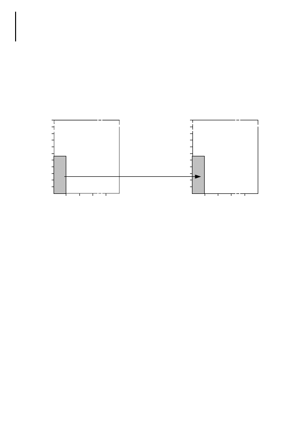
Service 20: Reading the PLC clock of the partner
station
When performing this service, the clock data for
station B, increased by the
time_adjust
value is
relayed to station A and output at the
rec_clock
FB
output of station A. The service is Y2K compatible:
the 1999 year number is followed by the year
number 2000.
Use it in conjunction with the function block
lock_time input and you can define whether station
A clock time is to be synchronised.
lock_time:=1: Read PLC clock of station B
The clock data of station B is increased by the
time_adjust value (of station A) and applied to the
rec_clock
FB output of station A.
Figure 10: lock_time:=1: Read the PLC clock of station B
lock_time:=1
rec_clock
Year
Month
Day
Weekday
Hour
Minute
Second
time_adjust
Station A
Date and time
Station A
Station B
RAM memory
RAM memory
Services
45
01
/99
A
W
B
27-
13
00-
G
B
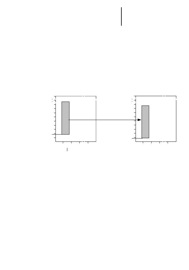
lock_time:=0: Synchronising to the PLC clock of
the partner station
Station B time data is increased by the
time_adjust
value (of station B). The new time value is output at
the
rec_clock
FB output and overwrites the PLC clock
data of station A.
Figure 11: lock_time:=0 Synchronising to the PLC clock of
station B
Date and time
Station A
Station B
RAM memory
RAM memory
Date and time
lock_time:=0
rec_clock
time_adjust
Station A
Year
Month
Day
Weekday
Hour
Minute
Second
Year
Month
Day
Weekday
Hour
Minute
Second
Function Blocks
46
01
/99
A
W
B
27-
13
00-
G
B
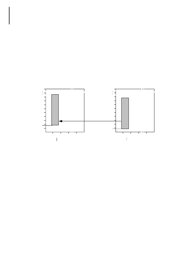
Service 21: Synchronising the PLC clock of the
partner station
Station A time data is increased by the
time_adjust
value (of station B) and the clock data of Station B
are then overwritten. If the
lock_time
FB input of
station B becomes active, no clock time
synchronisation takes place and 42H message code
is indicated.
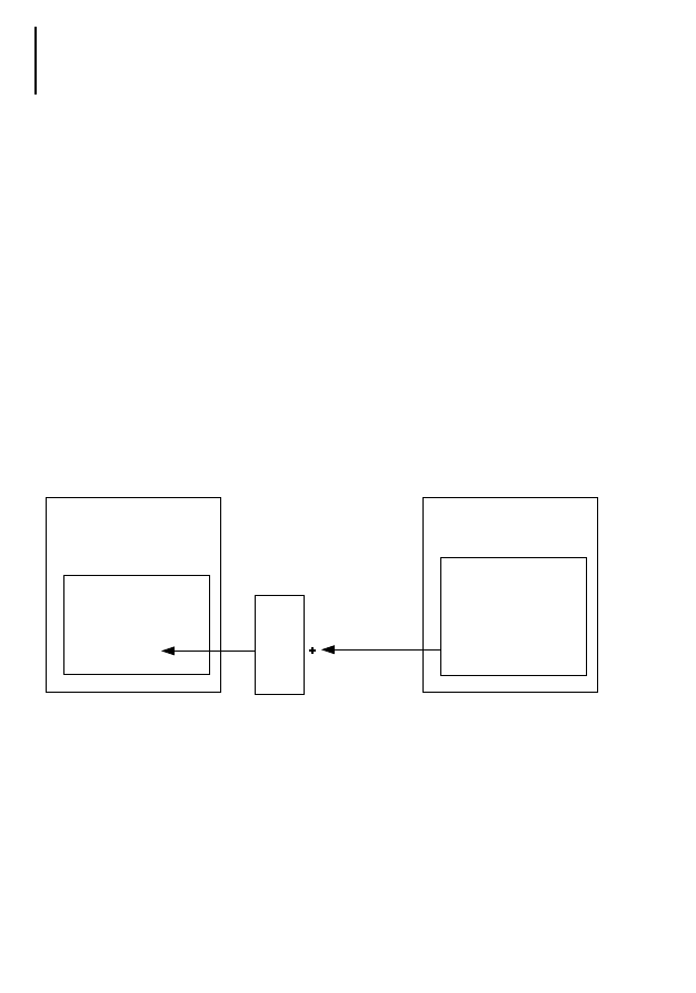
Figure 12: Service 21: Synchronising the PLC clock of
station B
Service 30: Remote Reset
This service can be activated only in those stations
in which the
station_type
FB input has the value
parameter 1. At the same time, the partner station
must be allocated a parameter value of 0. If these
conditions are met, the partner station will have
basic status. Basic status: error counters and frame
sequence bit are reset.
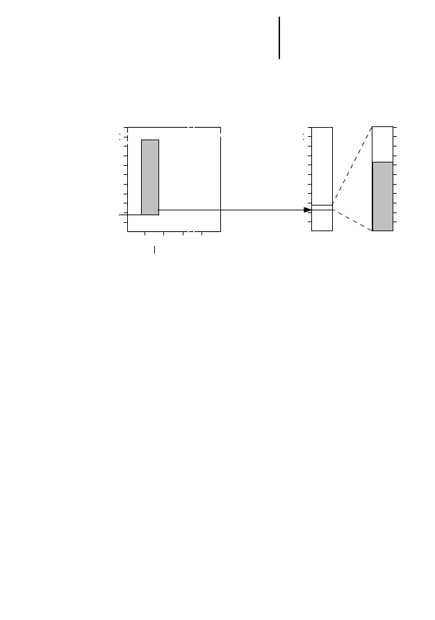
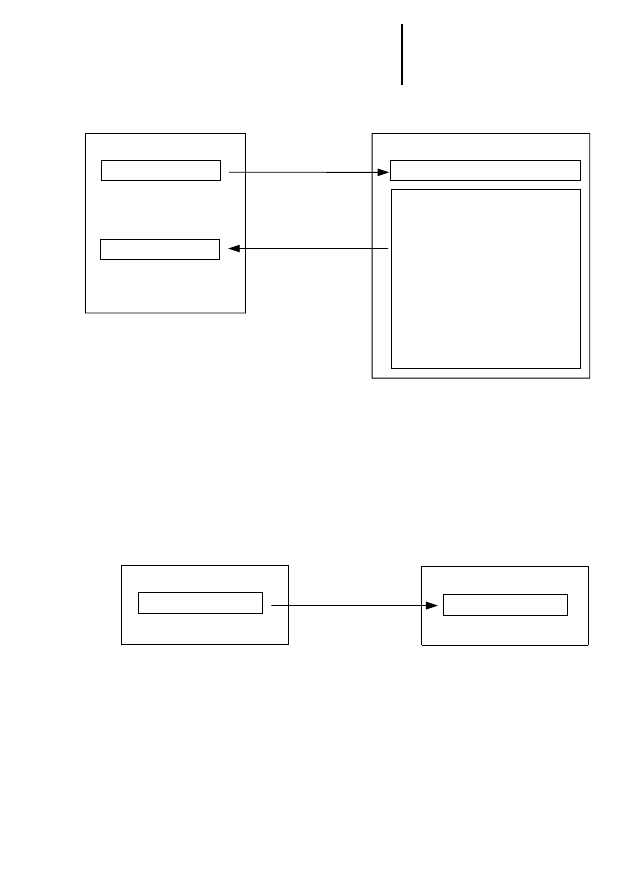
Service 31: Read status
When performing service 31, the parameters and
error counters of station B are transferred to station
A where they are consigned to the
rec_status_array
array.
time_adjust:=
Station B
Year
Month
Day
Weekday
Hour
Minute
Second
Year
Month
Day
Weekday
Hour
Minute
Second
Date and time
Station A
Station B
RAM memory
RAM memory
Date and time
Services
47
01
/99
A
W
B
27-
13
00-
G
B
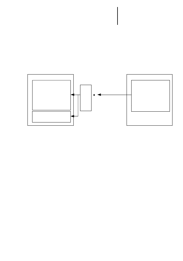
Figure 13: Service 31: Read status
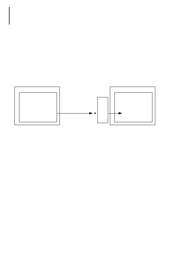
Service 33: Send information string
This service is used to relay the string at the
tra_information
FB input of station A to station B and
to output the
rec_information
FB output at station B.
Figure 14: Service 33: Send information string
RAM memory
Station A
RAM memory
Station B
Transmit frames counter
Receive frames counter
Protocol errors counter
Frame errors counter
Local errors counter
Other errors counter
Dial-up repeats counter
Alarms counter
tra_status
rec_status_array[0]
rec_status_array
tra_status
fixed_lenght
dial_repeat
dial_timeout
dial_wait
RAM memory
Station A
Station B
RAM memory
tra_information
rec_information

48
01
/99
A
W
B
27-
13
00-
G
B

49
01
/99
A
W
B
27-
13
00-
G
B
4
Operating Behaviour
Connection
establishment
After each connection has been made, the active
station checks whether an identical
com_ref_n
communication reference has been entered at the
partner station. If a valid entry is found, the “Read
status” service 31 is started automatically. After
establishment of a connection and positive
identification of the stations, the ready FB output
indicates that the telecontrol services can now be
started.
If the identification is negative, the partner station
acknowledges this and indicates error code 40h; no
services can then be transmitted.
Data communication between the tra_dat and
rec_dat now takes place in the area for which a valid
communication reference has been found.
Password
There are two ways of protecting a station against
unauthorised access:
Communication reference
For a communications relationship to be set up once
a positive connection has been established, the
stations automatically check, via the call function
blocks, whether identical
com_ref_n
communication
references have been entered. One UNIT is available
for the value range (1 – 65534). Non-matching
communications references generate an error
message.
Therefore only those stations sending a
communications reference with a corresponding
reference for
com_ref_n
FB inputs of the partner
station can communicate with one another.

Operating Behaviour
50
01
/99
A
W
B
27-
13
00-
G
B
Service 33 – Send information string
Each telecontrol station has the ability, via
lock_station
FB input, to protect itself against access
by other stations. In these circumstances, all
incoming services other than service 33 are
rejected.
Example:
Station A acts as controlling station and station B as
an outstation. Station B has shielded itself from
access by other stations via the
lock_station
FB input.
The password of station B is “Model station”.
Once a positive connection has been established by
station A via the call function block, it sends the
“model station” text string (
tra_information:=’model
station’
) via service 33 to station B. There, the text
string at the telecontrol rec_information FB output
(
‘model station’:=rec_information
) is indicated.
The text string received is then compared with an
internal password and, if it matches, the
lock_station
FB input is reset. Station A can now exchange all
available services with station B.
If the connection between the stations is broken, the
content of the
rec_information
FB output (vacant
string) is set and the
lock_station
function is
reactivated.
At the controlling station, you must activate service
33 via the user program. At the outstation, you must
observe the following program steps. You must also
make any appropriate entries in the variables
declaration.

Start-up behaviour
51
01
/99
A
W
B
27-
13
00-
G
B
VAR
lock_station AT %I0.0.0.0.0: BOOL;
password : STRING:=´Model station´;
dial : TCD_UNI ;
line : S40T1U0;
END_VAR
ld line.rec_information (*Information string,
telecontrol FB output*)
ne password (*Password*)
and lock_station (*Lock variable*)
st dial.lock_station (*Station locked,
call FB input*)
:
:
:
Cal dial
(
lock_station:=,
)
:
:
Cal line (
:=rec_information,
)
:
END_PROGRAM
Start-up behaviour After controller warm start or cold start or after
function block reset, interface parameters are
relayed from the PLC to the module/card. Should
the parameters contain incorrect adjustments (e.g.
invalid transmission rate of 610 baud) the preset
parameters are adopted and an error message is
generated. See also ”Error Codes“ on page 53.
Table 14: Default interface parameters in dial-up lines
Baud rate Start bit
(fixed
value)
Data bit Parity bit Stop bit
9600 1 8 even 1

Operating Behaviour
52
01
/99
A
W
B
27-
13
00-
G
B
If interface parameters are relayed to the module/
card, the modem is initialised with a time delay of
5 seconds. The module/card and the modem are
then ready for operation (modem code=0).
Further information on the startup behaviour is given
in the relevant telecontrol hardware manuals
(AWBs), in the chapter “Operation”.

53
01
/99
A
W
B
27-
13
00-
G
B
5
Error Codes
Call function blocks
Table 15 describes the error messages that may be
output during call function block processing. They
are indicated at the
fail_code
FB output.
Table 15: Call function block error codes
Error code
Meaning
HEX
DEC
20
32
The telecontrol module/card is not operationally ready.
Check that module/card ZB 4-501-TC1 or PS 416-
TCS-200 has been installed correctly.
Telecontrol card PS 416-TCS-200 has been installed
in the wrong slot. The slot number address
slotnumber
set on the function block must correspond
with the slot of PS 416-TCS-200 in the rack.
21
33
Wrong slot number
The value entered on the
slotnumber
FB input is
invalid. Input a valid value.
22
34
No communication reference.
No communication reference has been entered on the
telecontrol function block for the station number
entered on the
requested_station
FB input. Input a
valid communication reference.
23
35
No telephone number input
No telephone number has been entered on the
telecontrol function block for the station number
entered on the
requested_station
FB input. Input a
valid telephone number.
26
38
Character format parameter error
An invalid parameter has been entered on the FB
inputs
cmd_format
or char_
format
. Select a valid
character format.
27
39
Baud rate parameter error
An invalid error has been entered on the baud rate FB
input. Select a baud rate appropriate for the valid
value range for the
baudrate.
Input on page 24.

Error Codes
54
01
/99
A
W
B
27-
13
00-
G
B
Telecontrol function
blocks
The error codes are displayed via the
fail_code
FB
output
Table 16 describes the local error messages that
may be output whilst the telecontrol function blocks
are processing.
Table 16: Error messages from the telecontrol station
28
40
String error
An error has occurred during generation of the
initialisation or call strings. Check whether valid
parameters have been assigned on the
init_string
,
dial_prefix
,
baudrate
function block inputs (all call
function blocks) and
phone_number_n
(telecontrol
function block).
2D
45
The modem fails to make any connection or else the
connection has been cleared by the partner station.
After success in establishing a connection, the error
code is reset.
2E
46
The
dial_timeout
FB input set has expired and the
connection cleared.
2F
47
Time overshoot
A time overshoot has occurred in communication
between the function blocks and the modem and/or
the telecontrol card/module. RESET or switch off the
controller and the modem and then switch on again.
Error code
Meaning
HEX
DEC
Error code
Meaning
HEX
DEC
31
49
Service invalid
The code for the command function block input is
invalid.
Select a valid code number per table 13 on page 35.
32
50
Service disabled
The command service set at the FB input is disabled for
the type of station employed (station type:=0).
Choose another service or give the
stationtype
the
parameter value 1.

Telecontrol function blocks
55
01
/99
A
W
B
27-
13
00-
G
B
34
52
fixed_length
parameter incorrect.
The
fixed_length
value entered at the FB input does
not agree with the parameter in the card/module.
Reset block or carry out a warm or cold start in order to
transfer the modified value into the module.
35
53
Data length in fixed length frame incorrect
The
fixed_length
parameter entered at the FB input is
equal to 0 or exceeds the parameter set for the offset
address data array.
Check the parameters and input a permissible value for
fixed_length
.
36
54
Data length or offset address incorrect
Addition of the input parameters to the
tra_variable_length
and
tra_source_offset
and/or
tra_destination_offset
at the FB inputs exceeds the
value entered in the variable declaration for the
constants
tra_dfl_max
or
rec_dfl_max
.
Check the parameters and input a permissible value for
tra_variable_length
or
tra_source_offset
and/or
tra_destination_offset
. The impermissible value 0
has been entered at the
tra_variable_length
FB
input. Enter a permissible value.
If the error message appears in conjunction with
access to FLASH memory or the RAM memory card
(service 13, service 16), an impermissible value has
been used for the data length (>128 bytes).
37
55
Subaddress too large
The parameter entered at the
tra_subaddress
FB input
exceeds the set value of the constant
tra_sub_max
.
Check the parameters and enter a permissible value for
the
tra_subaddress
.
Error code
Meaning
HEX
DEC

Error Codes
56
01
/99
A
W
B
27-
13
00-
G
B
38
56
Baud rate parameter error
The parameter entered at the
baudrate
FB input is not
permissible.
From the module/card manuals (AWBs) select a valid
value for the baud rate.
39
57
Character format parameter error
The telecontrol module/card has been assigned an
incorrect character format.
Switch off and then switch on the controller in order to
remove the error.
3A
58
Frame type parameter error
The telecontrol module/card has been assigned an
incorrect frame type parameter.
Switch off and then switch on the controller in order to
remove the error.
3B
59
Signal quality error DCD evaluation
Modem signal quality monitoring has resulted in the
posting of a message on the DCD line.
Check your telephone line
3D
61
Absence of DSR signal
The modem coupled is not ready for operation.
Check the functional reliability of the connected
modem.
3E
62
Timeout CTS signal
The modem does not respond to the RTS signal of the
telecontrol module/card.
Check the functional reliability of the connected
modem and of the connecting lead.
3F
63
Timeout error
The telecontrol partners fail to respond.
7F
127
Communication error
The data received by the station is unintelligible.
Ensure that
all stations have the same baud rate setting
there are no problems with the transmission lines
the modems are working smoothly.
Error code
Meaning
HEX
DEC

Telecontrol function blocks
57
01
/99
A
W
B
27-
13
00-
G
B
Table 17 describes the error codes generated in a
partner station. These error codes are output at the
fail_code
output of the telecontrol station and partner
station function block.
Table 17: Partner station error messages
Error code
Meaning
HEX
DEC
40
64
Invalid communication reference.
After a connection has been established successfully,
no corresponding communication reference is
discovered at the partner station. Check the entries in
the
com_ref_n
FB inputs.
41
65
Data access disabled (
lock_data
)
The
lock_data
FB input is activated in the partner
station and the station performs a service whereby
data is written to the partner station RAM.
Select the station, choose another service for execution
or deactivate the
lock_data
FB input of the partner
station.
42
66
Time access disabled (
lock_time
)
The
lock_time
FB input is activated in the partner
station. The station will perform service 21 whereupon
the system clock of the partner station will be
overwritten.
Select another service to be performed at the partner
station or deactivate
thelock_time
FB input of the
partner station.
43
67
Flash access disabled (
lock_flash
)
The lock_flash FB input is activated in the partner
station. The station will perform service 13 whereupon
the data will be written to the FLASH of the partner
station.
Select another service to be performed at the partner
station or deactivate the
lock_flash
FB input of the
partner station.
44
68
fixed_length
parameter defective
The value entered for the
fixed_length
FB input does
not tally with the parameter in the partner station. For
all stations, set an identical value for
fixed_length
and
perform a block reset.

Error Codes
58
01
/99
A
W
B
27-
13
00-
G
B
45
69
Data length of a fixed length frame incorrect
The parameter entered at the
fixed_length
FB input is
equal to 0 or exceeds the set parameter of the data
array.
Check the parameter and enter a permissible value for
fixed_length
.
46
70
Data length or offset address defective
Addition of the parameters entered in the
tra_variable_length
and
tra_source_offset
or
tra_destination_offset FB inputs exceeds the value of
the constants
tra_dfl_max
or
rec_dfl_max
entered in
the variable declaration.
Check the parameters and enter a permissible value for
the variables.
The impermissible value 0 has been entered at the
tra_variable_length
FB input.
47
71
Subaddress too large
The parameter entered at the
tra_subaddress
FB input
exceeds the value of the constants
tra_sub_max
or
rec_sub_max
entered in the variable declaration.
Check the parameter and enter a permissible value for
tra_subaddress
.
48
72
Service not enabled
The service 30 performed is rejected by the partner
station because the
station_type
FB input of the
partner station has been assigned 0 value.
49
73
Frame sequence bit error
The frame sequence bit is used to prevent
communication loss or duplication. In the next frame to
the partner station, the frame sequence bits of the
stations are synchronised.
4A
74
Time synchronisation error
A system error has materialised when using service 21
at the polled station.
Check the station CPU.
Error code
Meaning
HEX
DEC

Telecontrol function blocks
59
01
/99
A
W
B
27-
13
00-
G
B
4B
75
lock_station
Access to the partner station by other stations is disab-
led. Deactivate the lock_station FB input of the partner
station.
4C
76
Error when writing to the FLASH/RAM memory card or
the FLASH/RAM memory card is not available. A
system error is encountered in the partner station using
service 13.
Check the FLASH memory of the CPU, the CPU of the
partner station or install the FLASH memory/ RAM
memory card.
4D
77
Error when reading the FLASH/RAM memory card or
the FLASH/RAM memory card is not available.
A system error has occurred in the partner station
using service 16.
Check the FLASH memory of the CPU, the partner
station CPU or install the FLASH memory/RAM memory
card.
7F
127
Communication error
Unintelligible data have been received from the station.
Ensure that
all stations have the same transmission rates set,
there are no disruptions to the transmission lines
the modems are working smoothly
Error code
Meaning
HEX
DEC

60
01
/99
A
W
B
27-
13
00-
G
B
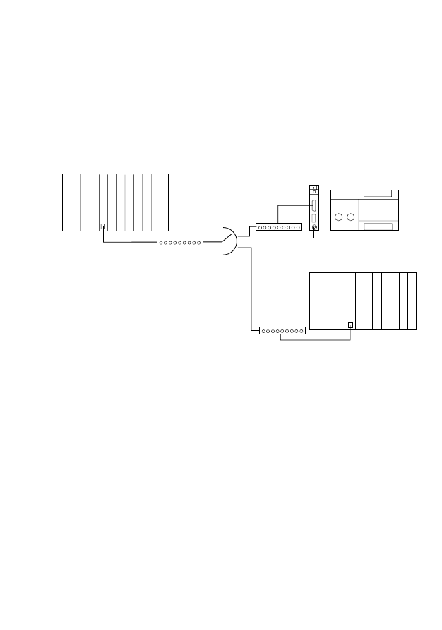
61
01
/99
A
W
B
27-
13
00-
G
B
6
Example
In the following example, three controllers are
communicating with one another via a dial-up line.
Figure 15: Sample configuration
Station A is acting as a controlling station and
gathers data from outstations B and C. At 22h00,
the controlling station sends 5 bytes of data to
outstation B and requests 30 bytes of data. At
23h00, the controlling station communicates
similarly with outstation C. In addition, the time of
the outstations is set to the time of the controlling
station as each connection is made.
PS 416-CPU
PS 416-T
CS-200
PS 416-T
CS-200
PS 4-200
ZB 4-501-TC1
PS 416
PS 416
PS 416-CPU
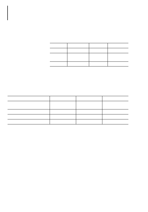
Example
62
01
/99
A
W
B
27-
13
00-
G
B
The stations are equipped with the following
hardware:
Table 18: Sample configuration: Hardware equipment
The following function blocks, communication
references and telephone numbers are selected for
the stations:
Table 19: Sample configuration: function blocks,
communication references and telephone numbers
With this information, the following input and output
parameters are assigned to the call function blocks
in the individual stations. The value allocation is thus
established.
Station
A
B
C
Controller
PS 416
PS 4-200
PS 416
Telecontrol
module/card
PS 416-TCS-200
ZB 4-501-TC1
PS 416-TCS-200
Modem
LGH 28.8D1
LGH 28.8D1
LGH 28.8D1
Station
A
B
C
Call function block
TCD_KE28
(local connection)
TCD_KE28
(local connection)
TCD_KE28
(local connection)
Telecontrol function block
S40T1_U1
S4T1_U0
S40T1_U0
Communication references
33/22
33
22
Telephone numbers
07222/400022
07222/400033
07222/400044

Example
63
01
/99
A
W
B
27-
13
00-
G
B
Table 20: Assigning the call function block parameters
The telecontrol function blocks are supplied with a
set of parameters based on a data transmission rate
of 20 bytes in send and receive directions.
Station
A
B
C
Call FB
TCD_KE28
TCD_KE28
TCD_KE28
Instance name
dial_A
dial_B
dial_C
reset:=
0
0
0
lock_station:=
0
0
0
dial:=
dial_repeat:=
2
2
2
dial_wait_repeat:=
T#30s
T#40s
T#50s
dial_timeout:=
T#30s
T#30s
T#30s
dial_praefix:=
’ATDP’
’ATDP’
’ATDP’
telegramformat:=
0
0
0
baudrate:=
9600
9600
9600
slotnumber:=
4
–
4
modem_response:=
fw_A.modem_response
fw_B.modem_response
fw_C.modem_response
modem_notify:=
fw_A.modem_notify
fw_B.modem_notify
fw_C.modem_notify
|
:=active
:=result
:=dcd
:=alarm
:=modem_request
fw_A.modem.request
fw_B.modem.request
fw_C.modem.request
:=modem_control
fw_A.modem_control
fw_B.modem_control
fw_C.modem_control
:=message
:=wait_time
:=modem_code
:=fail_code

Example
64
01
/99
A
W
B
27-
13
00-
G
B
In the telecontrol function block variable declaration,
you must match the data to the incident data:
You must assign parameters to the function block
inputs and outputs as follows:
Station
A
B
C
Telecontrol function block
S40T1_U1
S4T1_U0
S40T1_U0
Instance name
fw_A
fw_B
fw_C
VAR_INPUT
requested_station : USINT
(1..x) ;
(1..2)
(1..1)
(1..1)
tra_dat: ARRAY
[1..x,0..x,x..x] OF BYTE;
[1..2,0..0,0..4]
[1..1,0..0,0..29]
[1..1,0..0,0..29]
END_VAR
VAR_OUTPUT
rec_dat: ARRAY
[1..x,0..x,x..x] OF BYTE;
[1..2,0..0,0..29]
[1..1,0..0,0..4]
[1..1,0..0,0..4]
END_VAR
VAR_CONSTANT
tra_sub_max:USINT:=
x
0
0
0
rec_sub_max:USINT:=
x
0
0
0
tra_dfl_max:USINT:=
x
5
30
30
rec_dfl_max:USINT:=
x
30
5
5
END_VAR
Station
A
B
C
Telecontrol function block
S40T1_U1
S4T1_U0
S40T1_U0
Instance name
fw_A
fw_B
fw_C
strobe:=
station_type:=
0
1
1
requested_station:=
command:=
lock_data:=
lock_time:=
lock_flash:=
tel_repeat:=
2
2
2

Example
65
01
/99
A
W
B
27-
13
00-
G
B
time_adjust:=
1
1
1
fixed_length:=
user_status_1:=
user_status_2:=
user_status_3:=
user_status_4:=
tra_status:=
tra_variable_length:=
tra_subaddress:=
tra_source_offset:=
tra_destination_offset:=
tra_flash_segment:=
tra_dat:=
com_ref_1:=
33
33
22
com_ref_2:=
22
phone_number_1:=
07222400033
07222400022
07222400022
phone_number_2:=
07222400044
tra_information:=
modem_request:=
Station A: dial_A.modem_request
Station B: dial_B.modem_request
Station C: dial_C.modem_request
modem_control:=
Station A: dial_A.modem_control
Station B: dial_B.modem_control
Station C: dial_C.modem_control
:=ready
:=tra_active
:=tra_result
:=tra_fail
:=rec_active
:=rec_result
:=rec_fail
Station
A
B
C
Telecontrol function block
S40T1_U1
S4T1_U0
S40T1_U0
Instance name
fw_A
fw_B
fw_C

Example
66
01
/99
A
W
B
27-
13
00-
G
B
For controlling station A and outstations B and C,
you must now write programs importing the call and
telecontrol function blocks. Listed below are the
necessary program stages and variable declarations
that meet the functional data transmission
requirements.
:=rec_length
:=rec_subaddress
:=rec_offset
:=rec_flash_segment
:=rec_action
:=rec_com_ref
:=rec_information
:=rec_user_status
:=rec_clock
:=rec_status_array
:=com_ref_value
:=rec_dat
:=fail_code
:=modem_response
Station A: dial_A.modem_response
Station B: dial_B.modem_response
Station C: dial_C.modem_response
:=modem_notify
Station A: dial_A.modem_notify
Station B: dial_B.modem_notify
Station C: dial_C.modem_notify
Station
A
B
C
Telecontrol function block
S40T1_U1
S4T1_U0
S40T1_U0
Instance name
fw_A
fw_B
fw_C

Example
67
01
/99
A
W
B
27-
13
00-
G
B
Program listing in station A
Station A variable declaration program
VAR
dial_A
: TCD_KE28 ;
(*Call function block*)
fw_A
: S40T1_U1;
(*Telecontrol function block*)
start_time
: GetRealTimeClock ;
(*Real-time via function block*)
pf_ready
: R_TRIG ;
(*Rising edge when connection present*)
pf_start_cond1 : R_TRIG ;
(*Rising edge when time = 22:00*)
pf_start_cond2 : R_TRIG ;
(*Rising edge when time = 23:00*)
nf_tra_active
: F_TRIG ;
(*Falling edge, if the service has been
terminated*)
dial_start
: BOOL ;
(*Activate connection establishment*)
Count
: CTU ;
(*Function block counter*)
END_VAR
Station A POU program
CAL start_time(
(*Calling up the real time clock function block*)
|
:=Year,
:=Month,
:=Day,
:=Weekday,
:=Hour,
:=Minute,
:=Second)
(*Daily connection made to station B at 22h00*)
ld
start_time.hour
eq
22
st
pf_start_cond1.CLK
CAL pf_start_cond1(CLK :=
|
:=Q)
ld
pf_start_cond1.Q
jmpcn
end_station1
ld
1
st
fw_A.requested_station
ld
1
s
dial_start
end_station1:
(*Daily connection made to station C at 23h00*)
ld
start_time.hour
eq
23
st
pf_start_cond2.CLK

Example
68
01
/99
A
W
B
27-
13
00-
G
B
CAL pf_start_cond2(CLK :=
|
:=Q)
ld
pf_start_cond2.Q
jmpcn
end_station2
ld
2
st
fw_A.requested_station
ld
1
s
dial_start
end_station2:
(* Commencement of the 1
st
telecontrol service as soon as the connection has been made
and the station address has been recognised (ready=1). Other services are started when
the falling edge occurs at the tra_active FB output*)
CAL pf_ready (CLK :=fw_A.ready
|
:=Q)
(*Falling edge if the service has been terminated*)
CAL nf_tra_active (CLK :=fw_A.tra_active
|
:=Q)
ld
nf_tra_active.Q
and fw_A.tra_result
and
fw_A.ready
or
pf_ready.Q
st
count.CU
st
fw_A.strobe
ldn
dial_start
st
count.reset
(*Calling up the function block counter*)
CAL count(
CU :=,
RESET :=,
PV :=1000
|
:=Q,
:=CV
)
(*Sending 5 bytes to the partner station*)
ld
count.cv
eq
1
jmpcn
E1
ld
12
st fw_A.command

Example
69
01
/99
A
W
B
27-
13
00-
G
B
ld
5
st fw_A.tra_variable_length
E1:
(*Read 30 bytes from the partner station*)
ld
count.cv
eq
2
jmpcn
E2
ld
15
st fw_A.command
ld
30
st fw_A.tra_variable_length
E2:
(*Synchronise partner station clock time*)
ld
count.cv
eq
3
jmpcn
E3
ld
21
st fw_A.command
E3:
(*Connection broken*)
ld
count.cv
eq
4
jmpcn
E4
ld
1
r
dial_start
r
fw_A.strobe
E4:
(*Call function block. Interface, see table*)
Cal
dial_a(
:
|
:
)
(*Telecontrol function block. Interface, see table*)
Cal
fw_A(
:
|
:
)
End_of_program

Example
70
01
/99
A
W
B
27-
13
00-
G
B
Program listing in station B
Station B variable declaration
VAR
dial_B
: TCD_KE28 ;
(*Call function block*)
fw_B
: S4T1_U0;
(*Telecontrol function block*)
END_VAR
VAR_GLOBAL
TC1_rdata AT %RDB1.1.0.0 : ARRAY [1..36] OF BYTE ;
TC1_tdata AT %SDB1.1.0.0 : ARRAY [1..36] OF BYTE ;
END_VAR
Station B POU program
(*Call function block. Interface, see table*)
Cal
dial_B(
:
|
:
)
(*Telecontrol function block. Interface, see table*)
Cal
fw_B(
:
|
:
)
End_of_program

Example
71
01
/99
A
W
B
27-
13
00-
G
B
Program listing in station C
Station C variable declaration
VAR
dial_C : TCD_KE28 ;
(*Call function block*)
fw_C : S40T1_U0;
(*Telecontrol function block*)
END_VAR
Station B POU program
(*Call function block. Interface, see table*)
Cal
dial_C(
:
|
:
)
(*Telecontrol function block. Interface, see table*)
Cal
fw_C(
:
|
:
)
End_of_program

72
01
/99
A
W
B
27-
13
00-
G
B

73
01
/99
A
W
B
27-
13
00-
G
B
Glossary
Application module
Application modules are programs or parts of a
program for the PLC or PC that support a function
or completely execute a function in an application.
Application modules provide ready-made solutions
for the most diverse applications.
Asymmetrical configuration
Configurations of telecontrol stations consisting of
primary and secondary stations are known as
asymmetrical configurations.
Asynchronous transmission
Each communications character is synchronised
individually mainly via start and stop elements.
Character
Data format arrangement, e.g. 1 start bit, 8 data bits,
1 parity bit, 1 stop bit; i.e. 1 character = 11 bits.
Controlling station
The station remotely monitoring and/or remotely
controlling outstations.
DEE
Standing for Datenendeinrichtung, DEE is the
German equivalent of English data terminal
equipment or DTE.
Dial-up line
Transmission line that can be used via a dialling
process.
DTE
Data terminal equipment can, for example, be
computer terminals or other input/output
equipment. A DTE data sender is termed a data
source. A DTE data receiver is termed a data sink.

Glossary
74
01
/99
A
W
B
27-
13
00-
G
B
DTrE
Standing for data transmission equipment and the
English equivalent of the German DueE
(Datenuebertragungseinrichtung). See also under
modem.
Handshake
Established signal sequence for making and
controlling a connection.
ISO/OSI
The ISO/OSI model describes a model for dividing
data transmission and processing between two
computers.
Modem
Abbreviation for “modulator-demodulator”, a unit
which converts digital signals to analog and vice-
versa.
Parity
Data security process; a check bit added to each
character.
Secondary station
A station monitored or controlled and monitored by
a primary unit.
Symmetrical configuration
Configurations of telecontrol stations consisting of
stations of equal rank, are known as symmetrical
configurations. The stations in these configurations
combine the properties of primary and secondary
stations.
Telecontrol
Telecontrol is the monitoring and controlling of
geographically widely distributed processes via
serial by bit coded data transmission.

Glossary
75
01
/99
A
W
B
27-
13
00-
G
B
Telecontrol configuration
The combination of telecontrol stations and
transmission paths between stations.
Telecontrol station
Controlling station or outstation in a telecontrol
system
Telecontrol system
A telecontrol system is used for controlling and
monitoring geographically widely distributed
processes.
The system comprises all equipment and functions
for data acquisition, processing, transmission and
display of the necessary process information.

76
01
/99
A
W
B
27-
13
00-
G
B

77
01
/99
A
W
B
27-
13
00-
G
B
Index
A
Adapting the range limits in the variables declaration
Arrays ......................................................................... 15
Constants ................................................................... 14
Example ...................................................................... 15
Variables ..................................................................... 14
Arrays
Controlling station ...................................................... 15
Assigning parameters .................................................... 13
C
Call function block
Inputs .......................................................................... 23
Interface ..................................................................... 22
Outputs ....................................................................... 25
Call function blocks ................................................... 8, 21
Connection establishment ............................................. 49
Controlling station .......................................................... 15
D
Data array
Range limits ................................................................ 13
Data array access .......................................................... 18
Data array elements
Data array size ............................................................... 12
Data arrays ..................................................................... 11
Organisation ............................................................... 11
Working with ............................................................... 17
Dial repeats .................................................................... 24
Dial-up line ....................................................................... 6
Default interface parameters ...................................... 51
Dial-up prefix .................................................................. 27

Index
78
01
/99
A
W
B
27-
13
00-
B
E
Error codes ..................................................................... 53
Call function blocks .................................................... 53
Telecontrol function blocks ........................................ 54
Example .......................................................................... 61
F
Field of application ........................................................... 5
Function block .................................................................. 7
Type key ....................................................................... 7
Function block output
message
........................................ 27
Function blocks .............................................................. 21
G
Glossar ........................................................................... 73
H
Hardware requirements .................................................... 9
I
Initialisation string ........................................................... 26
Installation ........................................................................ 9
M
Making the connection to the partner station ................ 21
Modem
Communication display .............................................. 21
Initialising .................................................................... 21
Requirements .............................................................. 22
Modem codes ................................................................ 28
O
Offset address ................................................................ 12
Operating behaviour ....................................................... 49
Outstation ....................................................................... 16
P
Password ........................................................................ 49
POU ................................................................................ 10
R
Receive data ................................................................... 11
Receive data array .......................................................... 12

Index
79
01
/99
A
W
B
27-
13
00-
G
B
S
Send data ....................................................................... 11
Send data array .............................................................. 12
Services ......................................................................... 35
Service 10: Send data fixed frame length RAM ............. 36
Service 12: Send data variable frame length RAM ........ 37
Service 13: FLASH/RAM Memory card send data
variable frame length .................................................. 38
Service 15: RAM read data variable frame length ......... 40
Service 16: FLASH/RAM memory card read data
variable frame length .................................................. 41
Service 17: FLASH/RAM memory card read data fixed
frame length ............................................................... 42
Service 20: Reading the PLC clock
of the partner station .................................................. 44
Service 21: Synchronising the PLC clock
of the partner station .................................................. 46
Service 30: Remote Reset ............................................. 46
Service 31: Read status ................................................. 46
Service 33: Send information string ............................... 47
Severing the connection to the partner station ............. 21
Software requirements ..................................................... 9
Start-up behaviour ......................................................... 51
Status messages ........................................................... 27
Subaddress .................................................................... 12
T
Telecontrol function block
Inputs .......................................................................... 31
Outputs ....................................................................... 33
Telecontrol function blocks ............................................ 29
Type key ........................................................................... 7
U
User module S 40-AM-TD
Function blocks ............................................................ 8
User_status bit ............................................................... 18
V
Variables declaration
Range limits ................................................................ 14

80
01
/99
A
W
B
27-
13
00-
G
B
Document Outline
- About This Manual
- 1 General
- 2 Data Arrays
- 3 Function Blocks
- 4 Operating Behaviour
- 5 Error Codes
- 6 Example
- Glossary
- Index
- H1300U1f.pdf
- Téléconduite par ligne commutée
- S 40-AM-TD
- Module utilisateur
- U2_f_si1.pdf
- Avant de commencer les travaux d’installation
- U2_g_si1.pdf
- Before commencing the installation
- 1300U1g.pdf
Wyszukiwarka
Podobne podstrony:
akumulator do jeep grand cherokee i z 40 i 25 td
40 - 47, AM SZCZECIN, GMDSS ( GOC ), Egzamin
akumulator do land rover land rover discovery iii 40 v8 25 td
akumulator do audi a8 4e 30 tdi qquattro 40 tdi quattro 42 td
PS4 Sucosoft S 40 h1310g
TD 01
MSR 40 KOREFERAT NIERUCHOMOSCI INWEST
TD 09
TD 05
AM FM SSB Empfänger Teil 1
2006 EGZ WSTĘPNY NA AM
40
40 0610 013 05 01 7 General arrangement
Nasze opracowanie pytań 1 40
DTR KWSOI 40
cwiczenie8b am 13 14
page 40 41
39 40
więcej podobnych podstron