Transporter
Fitting Locations
No. 803 / 1
Edition 02.2010
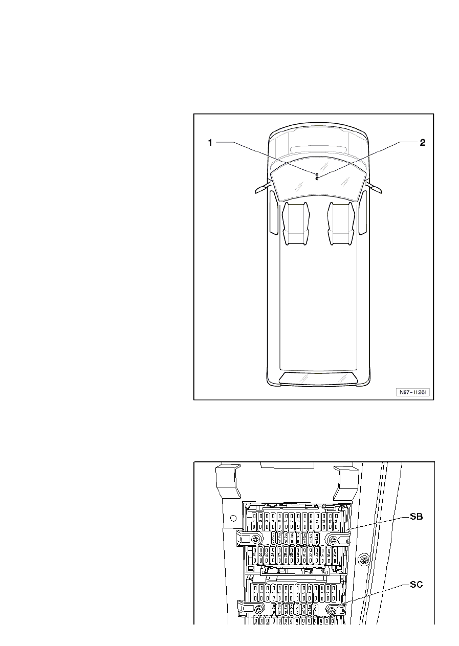
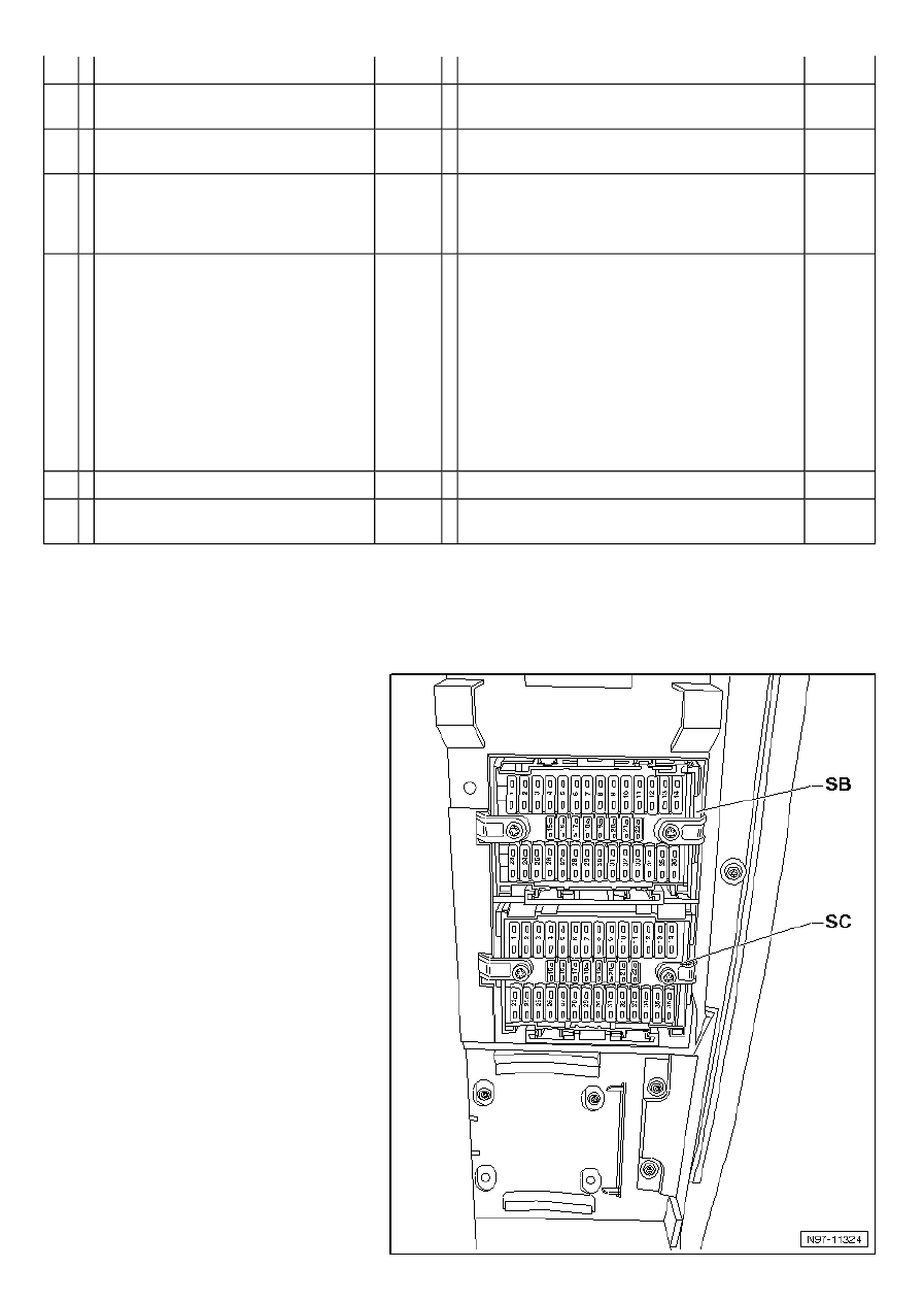
Interior fuses (SB and SC)
Overview of fuse carrier
1 - Fuses (SB) on fuse holder B, in
centre of dash panel
Location
→ chapter
from March 2003
→ chapter
from June 2004
→ chapter
from August 2006
→ chapter
from November 2007
→ chapter
2 - Fuses (SC) on fuse holder C, in
centre of dash panel
Location
→ chapter
from March 2003
→ chapter
from June 2004
→ chapter
from August 2006
→ chapter
from November 2007
→ chapter
Fuse (SB) on fuse holder B
Location:
In the upper fuse box on centre of
dash panel
Fuse colours
40 A - blue
30 A - green
25 A - white
20 A - yellow
15 A - blue
10 A - red
7.5 A - brown
5 A - beige
Page 1 of 22
WI-XML
24/01/2014
file://C:\ElsaWin\docs\slp\N\en-GB\K00589850803.htm

Page 2 of 22
WI-XML
24/01/2014
file://C:\ElsaWin\docs\slp\N\en-GB\K00589850803.htm
Transporter
Fitting Locations
No. 803 / 3
Position of fuses on fuse carrier B, from March 2003
No.
Current Flow Diagram designation
Nominal
value
Function/component
Terminal
1
- SB1 - Fuse 1 on fuse holder B
30 A
-
-
-
J18 - X-contact relay
J487 - Fresh air blower isolation relay
V306 - Rear blower Bitron regulation motor
3)
30
- SB1 - Fuse 1 on fuse holder B
25 A
- J487 - Fresh air blower isolation relay
4)
30
2
- SB2 - Fuse 2 on fuse holder B
5 A
- G85-steering angle sender
30
3
- SB3 - Fuse 3 on fuse holder B
10 A
- J519-Onboard power supply control unit
30
4
- SB4 - Fuse 4 on fuse holder B
10 A
-
-
-
E102 - Headlight range control regulator
V48 - Left headlight range control motor
V49 - Right headlight range control motor
56b
5
- SB5 - Fuse 5 on fuse holder B
15 A
- L1 - Left headlight twin filament bulb
M29 - Left headlight dipped beam bulb
S293 - Special vehicle fuse 3
2)
56b
6
- SB6 - Fuse 6 on fuse holder B
15 A
- L1 - Left headlight twin filament bulb
M30-Left main beam bulb
S296 - Special vehicle fuse 6
2)
56a
7
- SB7 - Fuse 7 on fuse holder B
15 A
- J519 - Onboard power supply control unit
(interior light)
30
8
- SB8 - Fuse 8 on fuse holder B
5 A
- T16 - 16-pin connector, diagnostic connector
30
9
- SB9 - Fuse 9 on fuse holder B
15 A
10 A
-
-
F - Brake light switch
1)
F - Brake light switch
2)
30
Note
1)
applicable up to August 2003
2)
applicable from September 2003
3)
applicable from June 2003
4)
applicable from February 2004
No.
Current Flow Diagram designation
Nominal
value
Function/component
Terminal
10 - SB10 - Fuse 10 on fuse holder B
5 A
-
-
E22 - Intermittent wiper switch
E34 - Rear wiper switch
15
11 - SB11 - Fuse 11 on fuse holder B
5 A
-
-
E20 - Switches and instruments illumination
regulator
X - number plate light
58
12 - SB12 - Fuse 12 on fuse holder B
15 A
- U1-Cigarette lighter
30
13 - SB13 - Fuse 13 on fuse holder B
5 A
-
-
J419 - Brake light additional relay
1)
J234 - Airbag control unit
2)
15
14 - SB14 - Fuse 14 on fuse holder B
30 A
-
-
-
-
E9 - Fresh air blower switch
E30 - Air conditioning system switch
J493-Auxiliary coolant heater relay
V305 - Front blower Bitron regulation motor
30
or
75
15 - SB15 - Fuse 15 on fuse holder B
7,5 A
-
-
-
E30 - Air conditioning system switch
J255 - Climatronic control unit
N280 - Air conditioning system compressor
regulating valve
15
16 - SB16 - Fuse 16 on fuse holder B
5 A
- J519-Onboard power supply control unit
15
Page 3 of 22
WI-XML
24/01/2014
file://C:\ElsaWin\docs\slp\N\en-GB\K00589850803.htm
17 - SB17 - Fuse 17 on fuse holder B
5 A
-
-
-
-
F216 - Rear fog light cut-out contact switch
K13 - Rear fog light warning lamp
L46 - Rear left fog light bulb
U10 -Trailer socket
RFL
18 - SB18 - Fuse 18 on fuse holder B
5 A
- J285 - Control unit in dash panel insert
30
Note
1)
applicable up to January 2004
2)
applicable from February 2004
No.
Current Flow Diagram designation
Nominal
value
Function/component
Terminal
19 - SB19 - Fuse 19 on fuse holder B
5 A
-
-
-
-
E153 - Operating and display unit for camping
equipment
J285 - Control unit in dash panel insert
J503 - Control unit with display for radio and
navigation system
J519-Onboard power supply control unit
J768 - Roof hydraulics control unit
R - Radio
86s
20 - SB20 - Fuse 20 on fuse holder B
5 A
-
-
-
-
-
M1 - Left side light bulb
M4 - Left tail light bulb
M21 - Left brake and tail light bulb
T10bh - 10-pin connector, purple
4)
U10 -Trailer socket
LPL
21 - SB21 - Fuse 21 on fuse holder B
5 A
-
-
-
-
M2 - Right tail light bulb
M3 - Right side light bulb
M22 - Right brake and tail light bulb
U10 -Trailer socket
RPL
22 - SB22 - Fuse 22 on fuse holder B
10 A
-
-
-
J285 - Control unit in dash panel insert
K45 - Front differential lock warning lamp
T16 - 16-pin connector, diagnostic connector
15
23 - SB23 - Fuse 23 on fuse holder B
25 A
25 A
5 A
-
-
-
U10 - Trailer socket
1)
B - Starter
2)
J207 - Starter inhibitor relay
3)
30
50
50
24 - SB24 - Fuse 24 on fuse holder B
5 A
- G85-steering angle sender
15
Note
1)
applicable up to January 2004
2)
applicable from February 2004, for manual gearbox only without
electric interface
3)
applicable from February 2004, manual gearbox with electric
interface
4)
for models with electric interface only (UF1)
No.
Current Flow Diagram designation
Nominal
value
Function/component
Terminal
25 - SB25 - Fuse 25 on fuse holder B
5 A
-
-
E30 - Air conditioning system switch
J255 - Climatronic control unit
30
26 - SB26 - Fuse 26 on fuse holder B
30 A
- E1 - Lighting switch
1)
75
27 - SB27 - Fuse 27 on fuse holder B
15 A
-
-
-
L2 - Right headlight twin filament bulb
M31 - Right headlight dipped beam bulb
S294 - Special vehicle fuse 4
2)
56b
28 - SB28 - Fuse 28 on fuse holder B
15 A
- K1 - Main beam warning lamp
56a
Page 4 of 22
WI-XML
24/01/2014
file://C:\ElsaWin\docs\slp\N\en-GB\K00589850803.htm

-
-
-
L2 - Right headlight twin filament bulb
M32-Right main beam bulb
S297 - Special vehicle fuse 7
2)
29 - SB29 - Fuse 29 on fuse holder B
- Vacant
-
Note
1)
applicable from February 2004
2)
for models with electric interface only (UF1)
No.
Current Flow Diagram designation
Nominal
value
Function/component
Terminal
30 - SB30 - Fuse 30 on fuse holder B
10 A
-
-
-
-
-
V12 - Rear window wiper motor
V92 - Rear left wing door window wiper motor
V93 - Rear right wing door window wiper motor
Z20 - Left washer jet heater element
Z21 - Right washer jet heater element
75
31 - SB31 - Fuse 31 on fuse holder B
30 A
- J519-Onboard power supply control unit (signal
horn)
30
32 - SB32 - Fuse 32 on fuse holder B
25 A
- J519-Onboard power supply control unit
(windscreen wiper motor)
30
33 - SB33 - Fuse 33 on fuse holder B
15 A
-
-
-
J503 - Control unit with display for radio and
navigation system
J559-Traffic information control unit
R - Radio
30
34 - SB34 - Fuse 34 on fuse holder B
25 A
-
-
-
-
G22-Speedometer sender
G70 - Air mass meter
J60 - Automatic gearbox relay
J623 - Engine control unit
15
35 - SB35 - Fuse 35 on fuse holder B
5 A
- Instruments illumination
58d
36 - SB36 - Fuse 36 on fuse holder B
25 A
- J519-Onboard power supply control unit (turn
signal)
30
Position of fuses on fuse carrier B, from June 2004
No.
Current Flow Diagram designation
Nominal
value
Function/component
Terminal
1
- SB1 - Fuse 1 on fuse holder B
25 A
- J487 - Fresh air blower isolation relay
30
- SB1 - Fuse 1 on fuse holder B
30 A
- V306-Rear blower Bitron regulation motor
30
2
- SB2 - Fuse 2 on fuse holder B
5 A
- G85-steering angle sender
30
3
- SB3 - Fuse 3 on fuse holder B
10 A
- J519-Onboard power supply control unit
30
4
- SB4 - Fuse 4 on fuse holder B
10 A
-
-
-
E102 - Headlight range control regulator
V48 - Left headlight range control motor
V49 - Right headlight range control motor
56b
5
- SB5 - Fuse 5 on fuse holder B
15 A
-
-
-
L1 - Left headlight twin filament bulb
M29 - Left headlight dipped beam bulb
S293 - Special vehicle fuse 3
2)
56b
6
- SB6 - Fuse 6 on fuse holder B
15 A
-
-
-
L1 - Left headlight twin filament bulb
M30-Left main beam bulb
S296 - Special vehicle fuse 6
2)
56a
7
- SB7 - Fuse 7 on fuse holder B
15 A
- J519 - Onboard power supply control unit
(interior light)
1)
30
8
- SB8 - Fuse 8 on fuse holder B
5 A
- T16-16-pin connector, diagnostic connector
30
Page 5 of 22
WI-XML
24/01/2014
file://C:\ElsaWin\docs\slp\N\en-GB\K00589850803.htm
9
- SB9 - Fuse 9 on fuse holder B
10 A
- F - Brake light switch
30
10 - SB10 - Fuse 10 on fuse holder B
10 A
-
-
E22 - Intermittent wiper switch
E34 - Rear wiper switch
15
11 - SB11 - Fuse 11 on fuse holder B
5 A
- X - number plate light
58
Note
1)
for models with roof console only
2)
for models with electric interface only (UF1)
No.
Current Flow Diagram designation
Nominal
value
Function/component
Terminal
12 - SB12 - Fuse 12 on fuse holder B
15 A
- U1-Cigarette lighter
30
13 - SB13 - Fuse 13 on fuse holder B
5 A
- J234 - Airbag control unit
15
14 - SB14 - Fuse 14 on fuse holder B
30 A
-
-
-
-
E9 - Fresh air blower switch
E30 - Air conditioning system switch
J493-Auxiliary coolant heater relay
V305 - Front blower Bitron regulation motor
30
or
75
15 - SB15 - Fuse 15 on fuse holder B
7,5 A
-
-
-
-
-
E30 - Air conditioning system switch
E159 - Fresh air/air recirculation flap switch
E179 - Rear fresh air blower switch
J255 - Climatronic control unit
N280 - Air conditioning system compressor
regulating valve
15
1)
15
2)
75
3)
16 - SB16 - Fuse 16 on fuse holder B
5 A
- J519-Onboard power supply control unit
15
17 - SB17 - Fuse 17 on fuse holder B
5 A
-
-
-
-
F216 - Rear fog light cut-out contact switch
K13 - Rear fog light warning lamp
L46 - Rear left fog light bulb
U10 -Trailer socket
RFL
18 - SB18 - Fuse 18 on fuse holder B
5 A
- J285 - Control unit in dash panel insert
30
Note
1)
for models with Climatronic only
2)
for models without Climatronic only, applicable up to December
2005
3)
for models without Climatronic only, applicable from January 2006
No.
Current Flow Diagram designation
Nominal
value
Function/component
Terminal
19 - SB19 - Fuse 19 on fuse holder B
5 A
-
-
-
-
-
-
-
E153 - Operating and display unit for camping
equipment
J285 - Control unit in dash panel insert
J503 - Control unit with display for radio and
navigation system
J519-Onboard power supply control unit
J768 - Roof hydraulics control unit
R - Radio
S291 - Special vehicle fuse 1
1)
86s
20 - SB20 - Fuse 20 on fuse holder B
5 A
-
-
-
-
-
M1 - Left side light bulb
M4 - Left tail light bulb
M21 - Left brake and tail light bulb
T10bh - 10-pin connector, purple
1)
U10 -Trailer socket
LPL
21 - SB21 - Fuse 21 on fuse holder B
5 A
-
-
-
M2 - Right tail light bulb
M3 - Right side light bulb
M22 - Right brake and tail light bulb
RPL
Page 6 of 22
WI-XML
24/01/2014
file://C:\ElsaWin\docs\slp\N\en-GB\K00589850803.htm
- U10 -Trailer socket
22 - SB22 - Fuse 22 on fuse holder B
10 A
-
-
-
J285 - Control unit in dash panel insert
K145 - Front passenger side airbag deactivated
warning lamp
T16-16-pin connector, diagnostic connector
15
Note
1)
for models without Climatronic only, applicable from January 2006
No.
Current Flow Diagram designation
Nominal
value
Function/component
Terminal
23 - SB23 - Fuse 23 on fuse holder B
40 A
25 A
30 A
5 A
-
-
-
-
B - Starter
1)
B - Starter
2)
B - Starter
3)
J207 - Starter inhibitor relay
4)
50
24 - SB24 - Fuse 24 on fuse holder B
5 A
- G85-steering angle sender
15
25 - SB25 - Fuse 25 on fuse holder B
5 A
-
-
-
E30 - Air conditioning system switch
E159 - Fresh air/air recirculation flap switch
J255 - Climatronic control unit
30
26 - SB26 - Fuse 26 on fuse holder B
30 A
- E1 - Lighting switch
75
27 - SB27 - Fuse 27 on fuse holder B
15 A
-
-
-
L2 - Right headlight twin filament bulb
M31 - Right headlight dipped beam bulb
S294 - Special vehicle fuse 4
5)
56b
28 - SB28 - Fuse 28 on fuse holder B
15 A
-
-
-
-
K1 - Main beam warning lamp
L2 - Right headlight twin filament bulb
M32-Right main beam bulb
S297 - Special vehicle fuse 7
5)
56a
29 - SB29 - Fuse 29 on fuse holder B
10 A
- J741-Dual signal inverter relay
30
Note
1)
for models with manual gearbox and without electric interface,
applicable up to December 2004
2)
for models with manual gearbox and without electric interface only,
applicable from January 2005 up to December 2005
3)
for models with manual gearbox and without electric interface only,
applicable from January 2006
4)
for models with manual gearbox and electric interface only
5)
for models with electric interface (UF1) only
No.
Current Flow Diagram designation
Nominal
value
Function/component
Terminal
30 - SB30 - Fuse 30 on fuse holder B
10 A
-
-
-
-
-
V12 - Rear window wiper motor
V92 - Rear left wing door window wiper motor
V93 - Rear right wing door window wiper motor
Z20 - Left washer jet heater element
Z21 - Right washer jet heater element
75
31 - SB31 - Fuse 31 on fuse holder B
30 A
- J519-Onboard power supply control unit (signal
horn)
30
32 - SB32 - Fuse 32 on fuse holder B
25 A
- J519-Onboard power supply control unit
(windscreen wiper motor)
30
33 - SB33 - Fuse 33 on fuse holder B
15 A
-
-
-
J503 - Control unit with display for radio and
navigation system
J559-Traffic information control unit
R - Radio
30
Page 7 of 22
WI-XML
24/01/2014
file://C:\ElsaWin\docs\slp\N\en-GB\K00589850803.htm
34 - SB34 - Fuse 34 on fuse holder B
25 A
-
-
-
-
-
-
-
-
-
-
-
J60 - Automatic gearbox relay
SD3 - Fuse 3 on fuse holder D
SD12-Fuse 12 on fuse holder D
SD14 - Fuse 14 on fuse holder D
SD15 - Fuse 15 on fuse holder D
SD16 - Fuse 16 on fuse holder D
SD17 - Fuse 17 on fuse holder D
SD19 - Fuse 19 on fuse holder D
SD20 - Fuse 20 on fuse holder D
SD24 - Fuse 24 on fuse holder D
D17 - Positive connection 1 (15), in engine
harness
15
35 - SB35 - Fuse 35 on fuse holder B
5 A
- Instruments illumination
58d
36 - SB36 - Fuse 36 on fuse holder B
25 A
- J519-Onboard power supply control unit (turn
signal)
30
Position of fuses in fuse holder B, from August 2006
No.
Current Flow Diagram designation
Nominal
value
Function/component
Terminal
1
- SB1 - Fuse 1 on fuse holder B
25 A
- J487 - Fresh air blower isolation relay
30
- SB1 - Fuse 1 on fuse holder B
30 A
- V306-Rear blower Bitron regulation motor
30
2
- SB2 - Fuse 2 on fuse holder B
5 A
- G85-steering angle sender
30
3
- SB3 - Fuse 3 on fuse holder B
10 A
- J519-Onboard power supply control unit
30
4
- SB4 - Fuse 4 on fuse holder B
10 A
-
-
-
E102 - Headlight range control regulator
V48 - Left headlight range control motor
V49 - Right headlight range control motor
56b
5
- SB5 - Fuse 5 on fuse holder B
15 A
-
-
-
L1 - Left headlight twin filament bulb
M29 - Left headlight dipped beam bulb
S293 - Special vehicle fuse 3
2)
56b
6
- SB6 - Fuse 6 on fuse holder B
15 A
-
-
-
L1 - Left headlight twin filament bulb
M30-Left main beam bulb
S296 - Special vehicle fuse 6
2)
56a
7
- SB7 - Fuse 7 on fuse holder B
15 A
- J519 - Onboard power supply control unit
(interior light)
1)
30
8
- SB8 - Fuse 8 on fuse holder B
5 A
- T16-16-pin connector, diagnostic connector
30
9
- SB9 - Fuse 9 on fuse holder B
10 A
- F - Brake light switch
30
10 - SB10 - Fuse 10 on fuse holder B
10 A
-
-
E22 - Intermittent wiper switch
E34 - Rear wiper switch
15
Note
1)
for models with roof console only
2)
for models with electric interface only (UF1)
No.
Current Flow Diagram designation
Nominal
value
Function/component
Terminal
11 - SB11 - Fuse 11 on fuse holder B
5 A
- X - number plate light
58
12 - SB12 - Fuse 12 on fuse holder B
15 A
- U1-Cigarette lighter
30
13 - SB13 - Fuse 13 on fuse holder B
5 A
- J234 - Airbag control unit
15
14 - SB14 - Fuse 14 on fuse holder B
30 A
-
-
-
E9 - Fresh air blower switch
E30 - Air conditioning system switch
J493-Auxiliary coolant heater relay
30
or
75
Page 8 of 22
WI-XML
24/01/2014
file://C:\ElsaWin\docs\slp\N\en-GB\K00589850803.htm

- V305 - Front blower Bitron regulation motor
15 - SB15 - Fuse 15 on fuse holder B
7,5 A
-
-
-
-
-
E30 - Air conditioning system switch
E159 - Fresh air/air recirculation flap switch
E179 - Rear fresh air blower switch
J255 - Climatronic control unit
N280 - Air conditioning system compressor
regulating valve
15
1)
75
2)
16 - SB16 - Fuse 16 on fuse holder B
5 A
- J519-Onboard power supply control unit
15
17 - SB17 - Fuse 17 on fuse holder B
5 A
-
-
-
-
F216 - Rear fog light cut-out contact switch
K13 - Rear fog light warning lamp
L46 - Rear left fog light bulb
U10 -Trailer socket
RFL
18 - SB18 - Fuse 18 on fuse holder B
5 A
- J285 - Control unit in dash panel insert
30
Note
1)
for models with roof console only
2)
for models without roof console only
No.
Current Flow Diagram designation
Nominal
value
Function/component
Terminal
19 - SB19 - Fuse 19 on fuse holder B
5 A
-
-
-
-
-
-
-
E153 - Operating and display unit for camping
equipment
J285 - Control unit in dash panel insert
J503 - Control unit with display for radio and
navigation system
J519-Onboard power supply control unit
J768 - Roof hydraulics control unit
R - Radio
S291 - Special vehicle fuse 1
1)
86s
20 - SB20 - Fuse 20 on fuse holder B
5 A
-
-
-
-
-
M1 - Left side light bulb
M4 - Left tail light bulb
M21 - Left brake and tail light bulb
T10bh - 10-pin connector, purple
1)
U10 -Trailer socket
LPL
21 - SB21 - Fuse 21 on fuse holder B
5 A
-
-
-
-
M2 - Right tail light bulb
M3 - Right side light bulb
M22 - Right brake and tail light bulb
U10 -Trailer socket
RPL
22 - SB22 - Fuse 22 on fuse holder B
10 A
-
-
-
-
J285 - Control unit in dash panel insert
K145 - Front passenger side airbag deactivated
warning lamp
T16-16-pin connector, diagnostic connector
T16j - 16-pin connector, diagnostic connector 2
2)
15
Note
1)
for models with electric interface (UF1) only
2)
applicable from June 2007
No.
Current Flow Diagram designation
Nominal
value
Function/component
Terminal
23 - SB23 - Fuse 23 on fuse holder B
30 A
5 A
-
-
B - Starter
1)
J207 - Starter inhibitor relay
2)
50
24 - SB24 - Fuse 24 on fuse holder B
5 A
- G85-steering angle sender
15
25 - SB25 - Fuse 25 on fuse holder B
5 A
-
-
E30 - Air conditioning system switch
E159 - Fresh air/air recirculation flap switch
30
Page 9 of 22
WI-XML
24/01/2014
file://C:\ElsaWin\docs\slp\N\en-GB\K00589850803.htm
- J255 - Climatronic control unit
26 - SB26 - Fuse 26 on fuse holder B
30 A
- E1 - Lighting switch
75
27 - SB27 - Fuse 27 on fuse holder B
15 A
-
-
-
L2 - Right headlight twin filament bulb
M31 - Right headlight dipped beam bulb
S294 - Special vehicle fuse 4
3)
56b
28 - SB28 - Fuse 28 on fuse holder B
15 A
-
-
-
-
K1 - Main beam warning lamp
L2 - Right headlight twin filament bulb
M32-Right main beam bulb
S297 - Special vehicle fuse 7
3)
56a
29 - SB29 - Fuse 29 on fuse holder B
10 A
- J741-Dual signal inverter relay
30
30 - SB30 - Fuse 30 on fuse holder B
10 A
-
-
-
-
-
V12 - Rear window wiper motor
V92 - Rear left wing door window wiper motor
V93 - Rear right wing door window wiper motor
Z20 - Left washer jet heater element
Z21 - Right washer jet heater element
75
Note
1)
for models with manual gearbox and without electric interface only
2)
for models with manual gearbox and with electric interface only
3)
for models with electric interface only (UF1)
No.
Current Flow Diagram designation
Nominal
value
Function/component
Terminal
31 - SB31 - Fuse 31 on fuse holder B
30 A
- J519-Onboard power supply control unit (signal
horn)
30
32 - SB32 - Fuse 32 on fuse holder B
25 A
- J519-Onboard power supply control unit
(windscreen wiper motor)
30
33 - SB33 - Fuse 33 on fuse holder B
15 A
-
-
-
J503 - Control unit with display for radio and
navigation system
J559-Traffic information control unit
R - Radio
30
34 - SB34 - Fuse 34 on fuse holder B
25 A
-
-
-
-
-
-
-
-
-
-
-
J60 - Automatic gearbox relay
SD3 - Fuse 3 on fuse holder D
SD12-Fuse 12 on fuse holder D
SD14 - Fuse 14 on fuse holder D
SD15 - Fuse 15 on fuse holder D
SD16 - Fuse 16 on fuse holder D
SD17 - Fuse 17 on fuse holder D
SD19 - Fuse 19 on fuse holder D
SD20 - Fuse 20 on fuse holder D
SD24 - Fuse 24 on fuse holder D
D17 - Positive connection 1 (15), in engine
harness
15
35 - SB35 - Fuse 35 on fuse holder B
5 A
- Instruments illumination
58d
36 - SB36 - Fuse 36 on fuse holder B
25 A
- J519-Onboard power supply control unit (turn
signal)
30
Position of fuses in fuse holder B, from November 2007
No.
Current Flow Diagram designation
Nominal
value
Function/component
Terminal
1
- SB1 - Fuse 1 on fuse holder B
25 A
- J487 - Fresh air blower isolation relay
30
- SB1 - Fuse 1 on fuse holder B
30 A
- V306-Rear blower Bitron regulation motor
30
Page 10 of 22
WI-XML
24/01/2014
file://C:\ElsaWin\docs\slp\N\en-GB\K00589850803.htm
2
- SB2 - Fuse 2 on fuse holder B
5 A
- G85-steering angle sender
30
3
- SB3 - Fuse 3 on fuse holder B
10 A
- J519-Onboard power supply control unit
30
4
- SB4 - Fuse 4 on fuse holder B
10 A
-
-
-
E102 - Headlight range control regulator
V48 - Left headlight range control motor
V49 - Right headlight range control motor
56b
5
- SB5 - Fuse 5 on fuse holder B
15 A
-
-
-
L1 - Left headlight twin filament bulb
M29 - Left headlight dipped beam bulb
S293 - Special vehicle fuse 3
2)
56b
6
- SB6 - Fuse 6 on fuse holder B
15 A
-
-
-
L1 - Left headlight twin filament bulb
M30-Left main beam bulb
S296 - Special vehicle fuse 6
2)
56a
7
- SB7 - Fuse 7 on fuse holder B
15 A
- J519 - Onboard power supply control unit
(interior light)
1)
30
8
- SB8 - Fuse 8 on fuse holder B
5 A
- T16-16-pin connector, diagnostic connector
30
9
- SB9 - Fuse 9 on fuse holder B
10 A
- F - Brake light switch
30
10 - SB10 - Fuse 10 on fuse holder B
10 A
-
-
E22 - Intermittent wiper switch
E34 - Rear wiper switch
15
Note
1)
for models with roof console only
2)
for models with electric interface only (UF1)
No.
Current Flow Diagram designation
Nominal
value
Function/component
Terminal
11 - SB11 - Fuse 11 on fuse holder B
5 A
- X - number plate light
58
12 - SB12 - Fuse 12 on fuse holder B
15 A
- U1-Cigarette lighter
30
13 - SB13 - Fuse 13 on fuse holder B
5 A
- J234 - Airbag control unit
15
14 - SB14 - Fuse 14 on fuse holder B
-
- Vacant
-
30 A
- E4 - Headlight dipper/flasher switch
3)
30
15 - SB15 - Fuse 15 on fuse holder B
7,5 A
-
-
-
-
-
E30 - Air conditioning system switch
E159 - Fresh air/air recirculation flap switch
E179 - Rear fresh air blower switch
J255 - Climatronic control unit
N280 - Air conditioning system compressor
regulating valve
15
1)
75
2)
16 - SB16 - Fuse 16 on fuse holder B
5 A
- J519-Onboard power supply control unit
15
17 - SB17 - Fuse 17 on fuse holder B
5 A
-
-
-
-
F216 - Rear fog light cut-out contact switch
K13 - Rear fog light warning lamp
L46 - Rear left fog light bulb
U10 -Trailer socket
RFL
18 - SB18 - Fuse 18 on fuse holder B
5 A
- J285 - Control unit in dash panel insert
30
Note
1)
for models with Climatronic only
2)
for models without Climatronic only
3)
applicable from June 2008
No.
Current Flow Diagram designation
Nominal
value
Function/component
Terminal
19 - SB19 - Fuse 19 on fuse holder B
5 A
-
-
E153 - Operating and display unit for camping
equipment
86s
Page 11 of 22
WI-XML
24/01/2014
file://C:\ElsaWin\docs\slp\N\en-GB\K00589850803.htm
-
-
-
-
-
J285 - Control unit in dash panel insert
J503 - Control unit with display for radio and
navigation system
J519-Onboard power supply control unit
J768 - Roof hydraulics control unit
R - Radio
S291 - Special vehicle fuse 1
1)
20 - SB20 - Fuse 20 on fuse holder B
5 A
-
-
-
-
-
M1 - Left side light bulb
M4 - Left tail light bulb
M21 - Left brake and tail light bulb
T10bh - 10-pin connector, purple
1)
U10 -Trailer socket
LPL
21 - SB21 - Fuse 21 on fuse holder B
5 A
-
-
-
-
M2 - Right tail light bulb
M3 - Right side light bulb
M22 - Right brake and tail light bulb
U10 -Trailer socket
RPL
22 - SB22 - Fuse 22 on fuse holder B
7,5 A
-
-
-
-
J285 - Control unit in dash panel insert
K145 - Front passenger side airbag deactivated
warning lamp
T16-16-pin connector, diagnostic connector
T16j - 16-pin connector, diagnostic connector 2
15
Note
1)
for models with electric interface (UF1) only
No.
Current Flow Diagram designation
Nominal
value
Function/component
Terminal
23 - SB23 - Fuse 23 on fuse holder B
30 A
5 A
-
-
-
B - Starter
1)
J207 - Starter inhibitor relay
2)
T10bj - 10-pin connector, yellow
2)
50
24 - SB24 - Fuse 24 on fuse holder B
5 A
- G85-steering angle sender
15
25 - SB25 - Fuse 25 on fuse holder B
5 A
-
-
-
E30 - Air conditioning system switch
E159 - Fresh air/air recirculation flap switch
J255 - Climatronic control unit
30
26 - SB26 - Fuse 26 on fuse holder B
30 A
- E1 - Lighting switch
75
27 - SB27 - Fuse 27 on fuse holder B
15 A
-
-
-
L2 - Right headlight twin filament bulb
M31 - Right headlight dipped beam bulb
S294 - Special vehicle fuse 4
3)
56b
28 - SB28 - Fuse 28 on fuse holder B
15 A
-
-
-
-
K1 - Main beam warning lamp
L2 - Right headlight twin filament bulb
M32-Right main beam bulb
S297 - Special vehicle fuse 7
3)
56a
29 - SB29 - Fuse 29 on fuse holder B
10 A
- J741-Dual signal inverter relay
30
30 - SB30 - Fuse 30 on fuse holder B
10 A
-
-
-
-
-
V12 - Rear window wiper motor
V92 - Rear left wing door window wiper motor
V93 - Rear right wing door window wiper motor
Z20 - Left washer jet heater element
Z21 - Right washer jet heater element
75
Note
1)
for models with manual gearbox and without electric interface only
2)
for models with manual gearbox and with electric interface only
3)
for models with electric interface only (UF1)
No.
Current Flow Diagram designation
Nominal
Function/component
Terminal
Page 12 of 22
WI-XML
24/01/2014
file://C:\ElsaWin\docs\slp\N\en-GB\K00589850803.htm
value
31 - SB31 - Fuse 31 on fuse holder B
30 A
- J519-Onboard power supply control unit (signal
horn)
30
32 - SB32 - Fuse 32 on fuse holder B
25 A
- J519-Onboard power supply control unit
(windscreen wiper motor)
30
33 - SB33 - Fuse 33 on fuse holder B
15 A
-
-
-
J503 - Control unit with display for radio and
navigation system
J559-Traffic information control unit
R - Radio
30
34 - SB34 - Fuse 34 on fuse holder B
25 A
-
-
-
-
-
-
-
-
-
-
-
J60 - Automatic gearbox relay
SD3 - Fuse 3 on fuse holder D
SD12-Fuse 12 on fuse holder D
SD14 - Fuse 14 on fuse holder D
SD15 - Fuse 15 on fuse holder D
SD16 - Fuse 16 on fuse holder D
SD17 - Fuse 17 on fuse holder D
SD19 - Fuse 19 on fuse holder D
SD20 - Fuse 20 on fuse holder D
SD24 - Fuse 24 on fuse holder D
D17 - Positive connection 1 (15), in engine
harness
15
35 - SB35 - Fuse 35 on fuse holder B
5 A
- Instruments illumination
58d
36 - SB36 - Fuse 36 on fuse holder B
25 A
- J519-Onboard power supply control unit (turn
signal)
30
Fuses (SC) on fuse holder C
Location:
In the lower fuse box on centre of
dash panel
Fuse colours
30 A - blue
30 A - green
25 A - white
20 A - yellow
15 A - blue
10 A - red
7.5 A - brown
5 A - beige
Page 13 of 22
WI-XML
24/01/2014
file://C:\ElsaWin\docs\slp\N\en-GB\K00589850803.htm
Position of fuses in fuse holder C, from March 2003
No.
Current Flow Diagram designation
Nominal
value
Function/component
Terminal
1
- SC1 - Fuse 1 on fuse holder C
15 A
- U18 - 12 V socket -2-
30
2
- SC2 - Fuse 2 on fuse holder C
5 A
-
-
G303 - Interior monitor send and receive module
1
G305 - Interior monitor send and receive module
2
30
3
- SC3 - Fuse 3 on fuse holder C
5 A
-
-
V320 - Right auxiliary blower
V321 - Left auxiliary blower
75
4
- SC4 - Fuse 4 on fuse holder C
15 A
- U19-12 V socket 3
30
5
- SC5-Fuse 5 on fuse holder C
15 A
- J698-Refrigerator box
30
6
- SC6 - Fuse 6 on fuse holder C
5 A
- G226 -Oil level and oil temperature sender
15
7
- SC7 - Fuse 7 on fuse holder C
10 A
- J180 - Switch-over relay 1 for roof ventilator
30
8
- SC8 - Fuse 8 on fuse holder C
5 A
- J446 - Parking aid control unit
15
9
- SC9 - Fuse 9 on fuse holder C
5 A
- J453-Multifunction steering wheel control unit
30
10 - SC10 - Fuse 10 on fuse holder C
30 A
- R12 - Amplifier
30
11 - SC11 - Fuse 11 on fuse holder C
20 A
-
-
-
-
J393 - Convenience system central control unit
J558 - Left sliding door control unit
J605 - Rear lid control unit
J731-Right sliding door control unit
30
12 - SC12 - Fuse 12 on fuse holder C
5 A
-
-
J493 - Auxiliary coolant heater relay
1)
J419 - Brake light additional relay
2)
75
15
Note
1)
up to January 2004
2)
from February 2004
No.
Current Flow Diagram designation
Nominal
value
Function/component
Terminal
13 - SC13 - Fuse 13 on fuse holder C
5 A
-
-
-
E45-Cruise control system switch
E221 - Operating unit in steering wheel
F138 - Airbag coil connector and return spring
with slip ring
15
14 - SC14 - Fuse 14 on fuse holder C
5 A
- J412 - Mobile telephone operating electronics
control unit
30
15 - SC15 - Fuse 15 on fuse holder C
5 A
- J98-Gearshift indicator control unit
15
16 - SC16 - Fuse 16 on fuse holder C
5 A
- J503 - Control unit with display for radio and
navigation system
15
17 - SC17 - Fuse 17 on fuse holder C
5 A
7,5 A
-
-
E265 - Rear Climatronic operating and display
unit
1)
J519 - Onboard power supply control unit
(interior light)
2)
30
18 - SC18 - Fuse 18 on fuse holder C
5 A
-
-
E179 - Rear fresh air blower switch
E265 - Rear Climatronic operating and display
unit
2)
15
30
19 - SC19 - Fuse 19 on fuse holder C
5 A
- Y7 - Automatic anti-dazzle interior mirror
15
20 - SC20 - Fuse 20 on fuse holder C
10 A
- J519-Onboard power supply control unit (heated
exterior mirror)
30
21 - SC21 - Fuse 21 on fuse holder C
5 A
- G303 - Interior monitor send and receive module
15
Page 14 of 22
WI-XML
24/01/2014
file://C:\ElsaWin\docs\slp\N\en-GB\K00589850803.htm
1
22 - SC22 - Fuse 22 on fuse holder C
5 A
-
-
G65 - High-pressure sender
G238 - Air quality sensor
15
Note
1)
up to January 2004
2)
from February 2004
No.
Current Flow Diagram designation
Nominal
value
Function/component
Terminal
23 - SC23 - Fuse 23 on fuse holder C
5 A
1)
10 A
2)
-
-
-
-
E153 - Operating and display unit for camping
equipment
E407-Auxiliary heater operating and display unit
J708 - Residual heat relay
R149-Remote control receiver for auxiliary
coolant heater
30
24 - SC24 - Fuse 24 on fuse holder C
5 A
- E153 - Operating and display unit for camping
equipment
3)
15
25 - SC25 - Fuse 25 on fuse holder C
15 A
-
-
-
-
E94 - Heated driver seat regulator
E95 - Heated front passenger seat regulator
G59 - Driver seat temperature sensor
G60 - Front passenger seat temperature sensor
75
26 - SC26 - Fuse 26 on fuse holder C
10 A
- G24 - Tachograph
30
27 - SC27 - Fuse 27 on fuse holder C
15 A
-
-
L22 - Left fog light bulb
L23 - Right fog light bulb
FL
28 - SC28 - Fuse 28 on fuse holder C
5 A
- E43 - Mirror adjustment switch
15
29 - SC29 - Fuse 29 on fuse holder C
25 A
- J364 - Auxiliary heater control unit
30
Note
1)
up to May 2003
2)
from June 2003
3)
up to January 2004
No.
Current Flow Diagram designation
Nominal
value
Function/component
Terminal
30 - SC30 - Fuse 30 on fuse holder C
5 A
-
-
E153 - Operating and display unit for camping
equipment
J493 - Auxiliary coolant heater relay
3)
15
75
31 - SC31 - Fuse 31 on fuse holder C
25 A
- J245 - Sliding sunroof adjustment control unit
30
32 - SC32 - Fuse 32 on fuse holder C
20 A
- J39 - Headlight washer system relay
30
33 - SC33-Fuse 33 on fuse holder C
5 A
- G24 - Tachograph
15
34 - SC34 - Fuse 34 on fuse holder C
20 A
- V192 - Vacuum pump for brakes
3)
75
25 A
- U10 - Trailer socket
4)
30
35 - SC35 - Fuse 35 on fuse holder C
10 A
- J519-Onboard power supply control unit
30
36 - SC36 - Fuse 36 on fuse holder C¹)
SC36 - Fuse 36 on fuse holder C²)
SC36 - Fuse 36 on fuse holder C²)
15 A
5 A
5 A
-
-
-
U20 - 12 V socket -4-
E153 - Operating and display unit for camping
equipment
Special vehicles
30
15
15
Note
Page 15 of 22
WI-XML
24/01/2014
file://C:\ElsaWin\docs\slp\N\en-GB\K00589850803.htm

1)
applicable up to May 2004
2)
applicable from March 2004
3)
applicable up to January 2004
4)
applicable from February 2004
Position of fuses in fuse holder C, from June 2004
No.
Current Flow Diagram designation
Nominal
value
Function/component
Terminal
1
- SC1 - Fuse 1 on fuse holder C
25 A
- U10 -Trailer socket
30
2
- SC2 - Fuse 2 on fuse holder C
5 A
-
-
G305 - Interior monitor send and receive module
2
J529-Anti-theft and tilt system control unit
30
3
- SC3 - Fuse 3 on fuse holder C
5 A
-
-
V320 - Right auxiliary blower
V321 - Left auxiliary blower
75
4
- SC4 - Fuse 4 on fuse holder C
10 A
- J492 - Four-wheel drive control unit
15
5
- SC5-Fuse 5 on fuse holder C
10 A
- T6bn-6-pin connector, grey
75
6
- SC6 - Fuse 6 on fuse holder C
5 A
- G226 -Oil level and oil temperature sender
15
7
- SC7 - Fuse 7 on fuse holder C
10 A
- B320 - Positive connection -6- (30), in main
wiring harrness
1)
30
15 A
- U20 - 12 V socket -4-
2)
30
8
- SC8 - Fuse 8 on fuse holder C
5 A
- J446 - Parking aid control unit
15
9
- SC9 - Fuse 9 on fuse holder C
5 A
- J453-Multifunction steering wheel control unit
30
10 - SC10 - Fuse 10 on fuse holder C
30 A
- R12 - Amplifier
30
11 - SC11 - Fuse 11 on fuse holder C
15 A
- J605 - Rear lid control unit
30
- SC11 - Fuse 11 on fuse holder C
20 A
-
-
-
-
-
H12-Alarm horn
J393 - Convenience system central control unit
J558 - Left sliding door control unit
J605 - Rear lid control unit
J731-Right sliding door control unit
30
Note
1)
applicable up to December 2004
2)
applicable from January 2005
No.
Current Flow Diagram designation
Nominal
value
Function/component
Terminal
12 - SC12 - Fuse 12 on fuse holder C
5 A
10 A
-
-
J419-Brake light additional relay
J419 - Brake light additional relay
1)
15
13 - SC13 - Fuse 13 on fuse holder C
5 A
-
-
-
E45-Cruise control system switch
E221 - Operating unit in steering wheel
F138 - Airbag coil connector and return spring
with slip ring
15
14 - SC14 - Fuse 14 on fuse holder C
5 A
- J412 - Mobile telephone operating electronics
control unit
30
15 - SC15 - Fuse 15 on fuse holder C
5 A
- J98-Gearshift indicator control unit
15
16 - SC16 - Fuse 16 on fuse holder C
5 A
-
-
J503 - Control unit with display for radio and
navigation system
J412 - Mobile telephone operating electronics
control unit
15
17 - SC17 - Fuse 17 on fuse holder C
7,5 A
-
-
J519 - Onboard power supply control unit
(interior light)
30
Page 16 of 22
WI-XML
24/01/2014
file://C:\ElsaWin\docs\slp\N\en-GB\K00589850803.htm
B315 - Positive connection -1- (30), in main
wiring harrness
18 - SC18 - Fuse 18 on fuse holder C
5 A
- E179 - Rear fresh air blower switch
15
- SC18 - Fuse 18 on fuse holder C
5 A
- E265 - Rear Climatronic operating and display
unit
30
19 - SC19 - Fuse 19 on fuse holder C
5 A
- Y7 - Automatic anti-dazzle interior mirror
15
20 - SC20 - Fuse 20 on fuse holder C
10 A
- J519-Onboard power supply control unit (heated
exterior mirror)
30
21 - SC21 - Fuse 21 on fuse holder C
5 A
- J529-Anti-theft and tilt system control unit
15
22 - SC22 - Fuse 22 on fuse holder C
5 A
-
-
G65 - High-pressure sender
G238 - Air quality sensor
15
23 - SC23 - Fuse 23 on fuse holder C
10 A
-
-
-
-
E153 - Operating and display unit for camping
equipment
E407-Auxiliary heater operating and display unit
J708 - Residual heat relay
R149-Remote control receiver for auxiliary
coolant heater
30
24 - SC24 - Fuse 24 on fuse holder C
7,5 A
- B250-Positive connection in roof wiring harness
(interior lighting)
30g
Note
1)
for models with TSP only, applicable from October 2005
No.
Current Flow Diagram designation
Nominal
value
Function/component
Terminal
25 - SC25 - Fuse 25 on fuse holder C
15 A
-
-
-
-
E94 - Heated driver seat regulator
E95 - Heated front passenger seat regulator
J131 - Heated driver seat control unit
J132 - Heated front passenger seat control unit
75
- SC25 - Fuse 25 on fuse holder C
25 A
- J774 - Heated front seats control unit
4)
75
26 -
-
SC26 - Fuse 26 on fuse holder C
SC26 - Fuse 26 on fuse holder C
10 A
15 A
-
-
G24 - Tachograph
1)
U18 - 12 V socket -2-
2)
30
30
27 - SC27 - Fuse 27 on fuse holder C
15 A
-
-
L22 - Left fog light bulb
L23 - Right fog light bulb
55
28 - SC28 - Fuse 28 on fuse holder C
5 A
- E43 - Mirror adjustment switch
15
29 - SC29 - Fuse 29 on fuse holder C
25 A
- J364 - Auxiliary heater control unit
30
30 -
-
SC30 - Fuse 30 on fuse holder C
SC30 - Fuse 30 on fuse holder C
5 A
5 A
-
-
E153 - Operating and display unit for camping
equipment
J493-Auxiliary coolant heater relay
15
X
31 - SC31 - Fuse 31 on fuse holder C
25 A
- J245 - Sliding sunroof adjustment control unit
30
32 - SC32 - Fuse 32 on fuse holder C
20 A
- J39 - Headlight washer system relay
30
33 - SC33-Fuse 33 on fuse holder C
5 A
- G24 - Tachograph
15
34 - SC34 - Fuse 34 on fuse holder C
15 A
- U19-12 V socket 3
30
35 - SC35 - Fuse 35 on fuse holder C
10 A
- J519 - Onboard supply control unit (reversing
light models with automatic gearbox)
30
36 - SC36 - Fuse 36 on fuse holder C
5 A
-
-
E153 - Operating and display unit for camping
equipment
Special vehicles
3)
15
Note
1)
for models with tachograph
Page 17 of 22
WI-XML
24/01/2014
file://C:\ElsaWin\docs\slp\N\en-GB\K00589850803.htm
2)
Multivan without tachograph and second battery only
3)
for models with electric interface (UF1) only
4)
applicable from January 2006
Position of fuses in fuse holder C, from August 2006
No.
Current Flow Diagram designation
Nominal
value
Function/component
Terminal
1
- SC1 - Fuse 1 on fuse holder C
25 A
- U10 -Trailer socket
30
2
- SC2 - Fuse 2 on fuse holder C
5 A
-
-
G305 - Interior monitor send and receive module
2
J529-Anti-theft and tilt system control unit
30
3
- SC3 - Fuse 3 on fuse holder C
5 A
-
-
V320 - Right auxiliary blower
V321 - Left auxiliary blower
75
4
- SC4 - Fuse 4 on fuse holder C
10 A
- J492 - Four-wheel drive control unit
15
5
- SC5-Fuse 5 on fuse holder C
10 A
- T6bn-6-pin connector, grey
75
6
- SC6 - Fuse 6 on fuse holder C
5 A
- G226 -Oil level and oil temperature sender
15
7
- SC7 - Fuse 7 on fuse holder C
10 A
- B320 - Positive connection -6- (30), in main
wiring harrness (roof ventilator)
30
- SC7 - Fuse 7 on fuse holder C
15 A
- U20 - 12 V socket -4-
30
8
- SC8 - Fuse 8 on fuse holder C
5 A
- J446 - Parking aid control unit
15
9
- SC9 - Fuse 9 on fuse holder C
5 A
- J453-Multifunction steering wheel control unit
30
10 - SC10 - Fuse 10 on fuse holder C
30 A
- R12 - Amplifier
30
11 - SC11 - Fuse 11 on fuse holder C
15 A
- J605 - Rear lid control unit
30
- SC11 - Fuse 11 on fuse holder C
20 A
-
-
-
-
-
H12-Alarm horn
J393 - Convenience system central control unit
J558 - Left sliding door control unit
J605 - Rear lid control unit
J731-Right sliding door control unit
30
No.
Current Flow Diagram designation
Nominal
value
Function/component
Terminal
12 - SC12 - Fuse 12 on fuse holder C
5 A
10 A
-
-
J419-Brake light additional relay
J419 - Brake light additional relay
1)
15
13 - SC13 - Fuse 13 on fuse holder C
5 A
-
-
-
E45-Cruise control system switch
E221 - Operating unit in steering wheel
F138 - Airbag coil connector and return spring
with slip ring
15
14 - SC14 - Fuse 14 on fuse holder C
5 A
- J412 - Mobile telephone operating electronics
control unit
30
15 - SC15 - Fuse 15 on fuse holder C
5 A
- J98-Gearshift indicator control unit
15
16 - SC16 - Fuse 16 on fuse holder C
5 A
-
-
J412 - Mobile telephone operating electronics
control unit
J503 - Control unit with display for radio and
navigation system
15
17 - SC17 - Fuse 17 on fuse holder C
7,5 A
-
-
J519 - Onboard power supply control unit
(interior light)
B315 - Positive connection -1- (30), in main
wiring harrness
30
18 - SC18 - Fuse 18 on fuse holder C
5 A
- E179 - Rear fresh air blower switch
15
- SC18 - Fuse 18 on fuse holder C
5 A
- E265 - Rear Climatronic operating and display
unit
30
Page 18 of 22
WI-XML
24/01/2014
file://C:\ElsaWin\docs\slp\N\en-GB\K00589850803.htm
19 - SC19 - Fuse 19 on fuse holder C
5 A
- Y7 - Automatic anti-dazzle interior mirror
15
20 - SC20 - Fuse 20 on fuse holder C
10 A
- J519-Onboard power supply control unit (heated
exterior mirror)
30
21 - SC21 - Fuse 21 on fuse holder C
5 A
- J529-Anti-theft and tilt system control unit
15
22 - SC22 - Fuse 22 on fuse holder C
5 A
-
-
G65 - High-pressure sender
G238 - Air quality sensor
15
Note
1)
for models with TSP only
No.
Current Flow Diagram designation
Nominal
value
Function/component
Terminal
23 - SC23 - Fuse 23 on fuse holder C
10 A
-
-
-
-
E153 - Operating and display unit for camping
equipment
E407-Auxiliary heater operating and display unit
J708 - Residual heat relay
R149-Remote control receiver for auxiliary
coolant heater
30
24 - SC24 - Fuse 24 on fuse holder C
7,5 A
- B250-Positive connection in roof wiring harness
(interior lighting)
30g
25 - SC25 - Fuse 25 on fuse holder C
25 A
-
-
-
E94 - Heated driver seat regulator
E95 - Heated front passenger seat regulator
J774 -Heated front seats control unit
75
26 -
-
SC26 - Fuse 26 on fuse holder C
SC26 - Fuse 26 on fuse holder C
10 A
15 A
-
-
G24 - Tachograph
1)
U18 - 12 V socket -2-
2)
30
30
27 - SC27 - Fuse 27 on fuse holder C
15 A
-
-
-
L22 - Left fog light bulb
L23 - Right fog light bulb
S298 - Special vehicle fuse 8
3)
55
28 - SC28 - Fuse 28 on fuse holder C
5 A
-
-
E43 - Mirror adjustment switch
J386 - Driver door control unit
15
29 - SC29 - Fuse 29 on fuse holder C
25 A
- J364 - Auxiliary heater control unit
30
30 -
-
SC30 - Fuse 30 on fuse holder C
SC30 - Fuse 30 on fuse holder C
5 A
5 A
-
-
E153 - Operating and display unit for camping
equipment
J493-Auxiliary coolant heater relay
15
X
Note
1)
for models with tachograph
2)
Multivan without tachograph and second battery only
3)
for models with electric interface (UF1) only
No.
Current Flow Diagram designation
Nominal
value
Function/component
Terminal
31 - SC31 - Fuse 31 on fuse holder C
25 A
- J245 - Sliding sunroof adjustment control unit
30
- SC31 - Fuse 31 on fuse holder C
5 A
- A11 - Onboard supply charger unit
5)
30
32 - SC32 - Fuse 32 on fuse holder C
20 A
- J39 - Headlight washer system relay
30
33 - SC33-Fuse 33 on fuse holder C
5 A
15 A
15 A
-
-
-
G24 - Tachograph¹)
G24 - Tachograph²)
J351 - Folding exterior mirror control unit
2), 3)
15
34 - SC34 - Fuse 34 on fuse holder C
15 A
- U19-12 V socket 3
30
35 - SC35 - Fuse 35 on fuse holder C
10 A
- J519 - Onboard supply control unit (reversing
light models with automatic gearbox)
30
Page 19 of 22
WI-XML
24/01/2014
file://C:\ElsaWin\docs\slp\N\en-GB\K00589850803.htm
36 - SC36 - Fuse 36 on fuse holder C
5 A
-
-
E153 - Operating and display unit for camping
equipment
Special vehicles
4)
15
Note
1)
for models with tachograph
2)
for models with tachograph and electric folding exterior mirror only
3)
for models with electric folding exterior mirror only
4)
for models with electric interface only (UF1)
5)
for camper only, applicable from November 2006
Position of fuses in fuse holder C, from November 2007
No.
Current Flow Diagram designation
Nominal
value
Function/component
Terminal
1
- SC1 - Fuse 1 on fuse holder C
25 A
- U10 -Trailer socket
30
2
- SC2 - Fuse 2 on fuse holder C
5 A
-
-
G305 - Interior monitor send and receive module
2
J529-Anti-theft and tilt system control unit
30
3
- SC3 - Fuse 3 on fuse holder C
5 A
-
-
-
V320 - Right auxiliary blower
1)
V321 - Left auxiliary blower
1)
vacant
2)
75
4
- SC4 - Fuse 4 on fuse holder C
10 A
-
-
-
E121 - Rear differential lock switch
J187-Differential lock control unit
J492 - Four-wheel drive control unit
15
5
- SC5-Fuse 5 on fuse holder C
10 A
- T6bn-6-pin connector, grey
75
6
- SC6 - Fuse 6 on fuse holder C
5 A
- G226 -Oil level and oil temperature sender
15
7
- SC7 - Fuse 7 on fuse holder C
10 A
- B320 - Positive connection -6- (30), in main
wiring harrness (roof ventilator)
30
- SC7 - Fuse 7 on fuse holder C
15 A
- U20 - 12 V socket -4-
30
8
- SC8 - Fuse 8 on fuse holder C
5 A
- J446 - Parking aid control unit
15
9
- SC9 - Fuse 9 on fuse holder C
5 A
- J453-Multifunction steering wheel control unit
30
10 - SC10 - Fuse 10 on fuse holder C
30 A
- R12 - Amplifier
30
Note
1)
applicable up to May 2008
2)
applicable from June 2008
No.
Current Flow Diagram designation
Nominal
value
Function/component
Terminal
11 - SC11 - Fuse 11 on fuse holder C
15 A
- J605 - Rear lid control unit
30
- SC11 - Fuse 11 on fuse holder C
20 A
-
-
-
-
-
H12-Alarm horn
J393 - Convenience system central control unit
J558 - Left sliding door control unit
J605 - Rear lid control unit
J731-Right sliding door control unit
30
12 - SC12 - Fuse 12 on fuse holder C
5 A
10 A
-
-
J419-Brake light additional relay
J419 - Brake light additional relay
1)
15
13 - SC13 - Fuse 13 on fuse holder C
5 A
-
-
-
E45-Cruise control system switch
E221 - Operating unit in steering wheel
F138 - Airbag coil connector and return spring
15
Page 20 of 22
WI-XML
24/01/2014
file://C:\ElsaWin\docs\slp\N\en-GB\K00589850803.htm
with slip ring
14 - SC14 - Fuse 14 on fuse holder C
5 A
- J412 - Mobile telephone operating electronics
control unit
30
15 - SC15 - Fuse 15 on fuse holder C
5 A
- J98-Gearshift indicator control unit
15
16 - SC16 - Fuse 16 on fuse holder C
5 A
-
-
J503 - Control unit with display for radio and
navigation system
15
17 - SC17 - Fuse 17 on fuse holder C
7,5 A
-
-
J519 - Onboard power supply control unit
(interior light)
B315 - Positive connection -1- (30), in main
wiring harrness
30
18 - SC18 - Fuse 18 on fuse holder C
5 A
- E179 - Rear fresh air blower switch
15
- SC18 - Fuse 18 on fuse holder C
5 A
- E265 - Rear Climatronic operating and display
unit
30
19 - SC19 - Fuse 19 on fuse holder C
5 A
- Y7 - Automatic anti-dazzle interior mirror
15
Note
1)
for models with TSP only
No.
Current Flow Diagram designation
Nominal
value
Function/component
Terminal
20 - SC20 - Fuse 20 on fuse holder C
10 A
- J519-Onboard power supply control unit (heated
exterior mirror)
30
21 - SC21 - Fuse 21 on fuse holder C
5 A
- J529-Anti-theft and tilt system control unit
15
22 - SC22 - Fuse 22 on fuse holder C
5 A
-
-
G65 - High-pressure sender
G238 - Air quality sensor
15
23 - SC23 - Fuse 23 on fuse holder C
10 A
-
-
-
-
E153 - Operating and display unit for camping
equipment
E407-Auxiliary heater operating and display unit
J708 - Residual heat relay
R149-Remote control receiver for auxiliary
coolant heater
30
24 - SC24 - Fuse 24 on fuse holder C
7,5 A
- B250-Positive connection in roof wiring harness
(interior lighting)
30g
25 - SC25 - Fuse 25 on fuse holder C
25 A
-
-
-
E94 - Heated driver seat regulator
E95 - Heated front passenger seat regulator
J774 -Heated front seats control unit
75
26 -
-
SC26 - Fuse 26 on fuse holder C
SC26 - Fuse 26 on fuse holder C
10 A
15 A
-
-
G24 - Tachograph
1)
U18 - 12 V socket -2-
2)
30
30
27 - SC27 - Fuse 27 on fuse holder C
15 A
-
-
-
L22 - Left fog light bulb
L23 - Right fog light bulb
S298 - Special vehicle fuse 8
3)
55
Note
1)
for models with tachograph
2)
Multivan without tachograph and second battery only
3)
for models with electric interface (UF1) only
No.
Current Flow Diagram designation
Nominal
value
Function/component
Terminal
28 - SC28 - Fuse 28 on fuse holder C
5 A
-
-
E43 - Mirror adjustment switch
J386 - Driver door control unit
15
29 - SC29 - Fuse 29 on fuse holder C
25 A
- J364 - Auxiliary heater control unit
30
Page 21 of 22
WI-XML
24/01/2014
file://C:\ElsaWin\docs\slp\N\en-GB\K00589850803.htm
30 -
-
SC30 - Fuse 30 on fuse holder C
SC30 - Fuse 30 on fuse holder C
5 A
5 A
-
-
E153 - Operating and display unit for camping
equipment
J493-Auxiliary coolant heater relay
15
X
31 - SC31 - Fuse 31 on fuse holder C
25 A
- J245 - Sliding sunroof adjustment control unit
30
- SC31 - Fuse 31 on fuse holder C
5 A
- A11 - Onboard supply charger unit
4)
30
32 - SC32 - Fuse 32 on fuse holder C
20 A
- J39 - Headlight washer system relay
30
33 - SC33-Fuse 33 on fuse holder C
5 A
15 A
15 A
-
-
-
G24 - Tachograph
1)
G24 - Tachograph
2)
J351 - Folding exterior mirror control unit
2), 3)
15
34 - SC34 - Fuse 34 on fuse holder C
15 A
- U19-12 V socket 3
30
35 - SC35 - Fuse 35 on fuse holder C
10 A
- J519 - Onboard supply control unit (reversing
light models with automatic gearbox)
30
36 - SC36 - Fuse 36 on fuse holder C
5 A
-
-
E153 - Operating and display unit for camping
equipment
T10bh-10-pin connector, purple
15
Note
1)
for models with tachograph
2)
for models with tachograph and electric folding exterior mirror only
3)
for models with electric folding exterior mirror only
4)
for camper only
Page 22 of 22
WI-XML
24/01/2014
file://C:\ElsaWin\docs\slp\N\en-GB\K00589850803.htm
Wyszukiwarka
Podobne podstrony:
2010 03, str 050 052
2010 03, str 150 153
2010 03, str 040 044
bankowa analiza zdolności kredytowej (20 str), Finanse
2010 03, str 158 165
MOTYWOWANIE 20 STR , Zarządzanie projektami, Zarządzanie(1)
bankowość (20 str)
2010 03, str 182 187
2010 03, str 066 071
K Trybulski = Cytaty (Full 20 str)
2003 08 20
2003 05 20
2010 03, str 166 169
cytaty ludzi sukcesu full 20 str
2010 03, str 022 026
2003 11 20
2003 09 20
więcej podobnych podstron