1C – 68
I
DOHC ENGINE MECHANICAL
DAEWOO V–121 BL4
UNIT REPAIR
CYLINDER HEAD AND VALVE TRAIN
COMPONENTS
Tools Required
MKM–571–B Gauge
KM–340–0 Cutter Set
KM–340–7 Guide Drift
KM–340–13 Cutters
KM–340–26 Cutters
KM–348 Valve Spring Compressor
KM–653 Adapter
KM–805 Valve Guide Reamer
Disassembly Procedure
1. Remove the cylinder head with the intake manifold
and the exhaust manifold attached. Refer to ”Cylin-
der Head and Gasket” in this section.
2. Remove the coolant temperature sensor.
3. Remove the camshaft position sensor.
4. Remove the exhaust manifold heat shield bolts.
5. Remove the exhaust manifold heat shield.
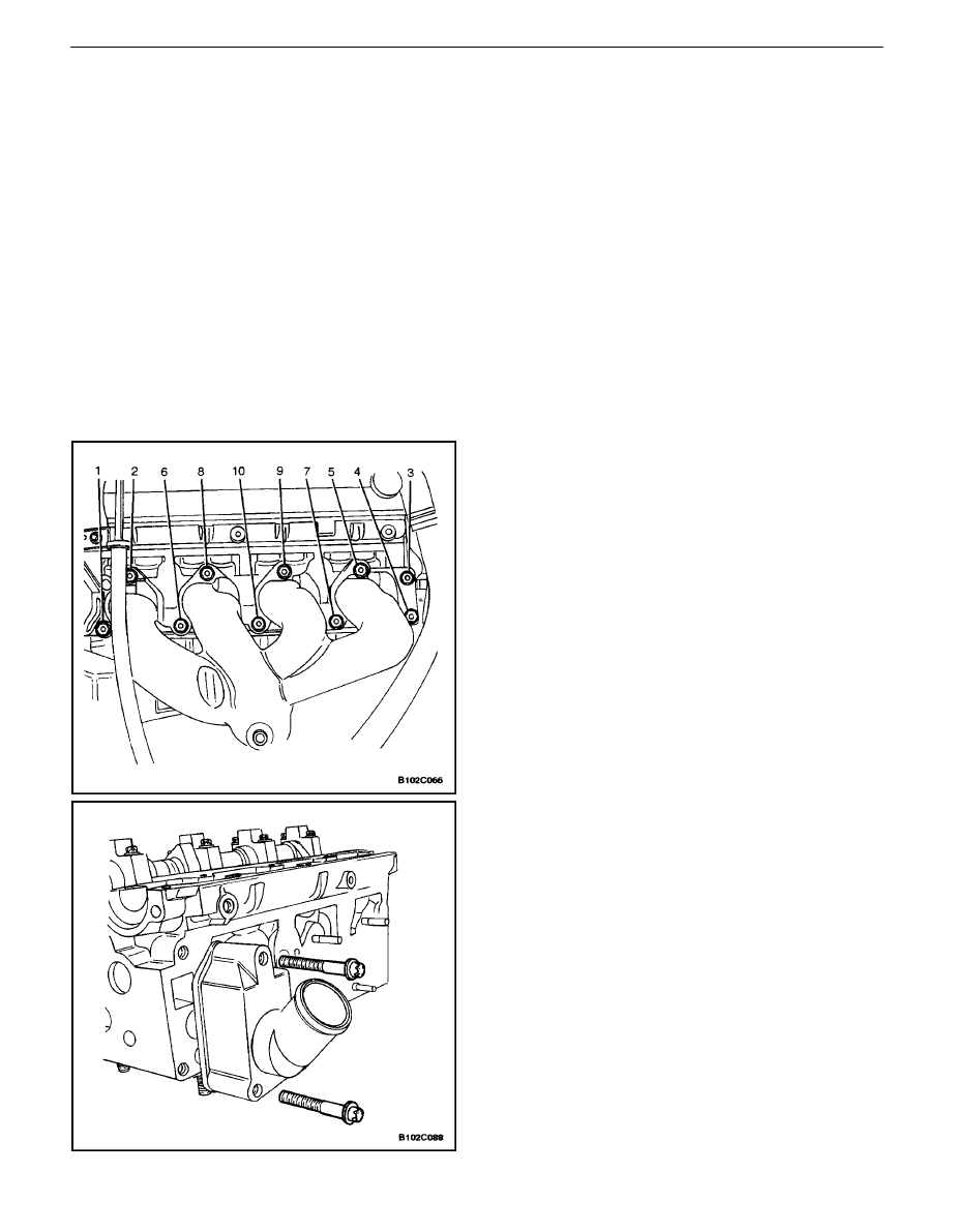
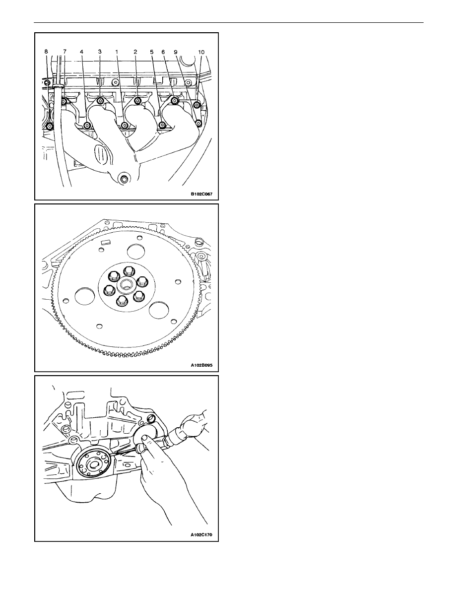
6. Remove the exhaust manifold retaining nuts in the
sequence shown.
7. Remove the exhaust manifold.
8. Remove the exhaust manifold gasket.
9. Remove the exhaust manifold studs.
10. Remove the thermostat housing mounting bolts.
11. Remove the thermostat housing assembly.
12. Remove the fuel rail assembly. Refer to Section 1F,
Engine Controls (DOHC).
13. Remove the coolant bypass housing mounting bolts
and the housing.
DOHC ENGINE MECHANICAL 1C – 69
DAEWOO V–121 BL4
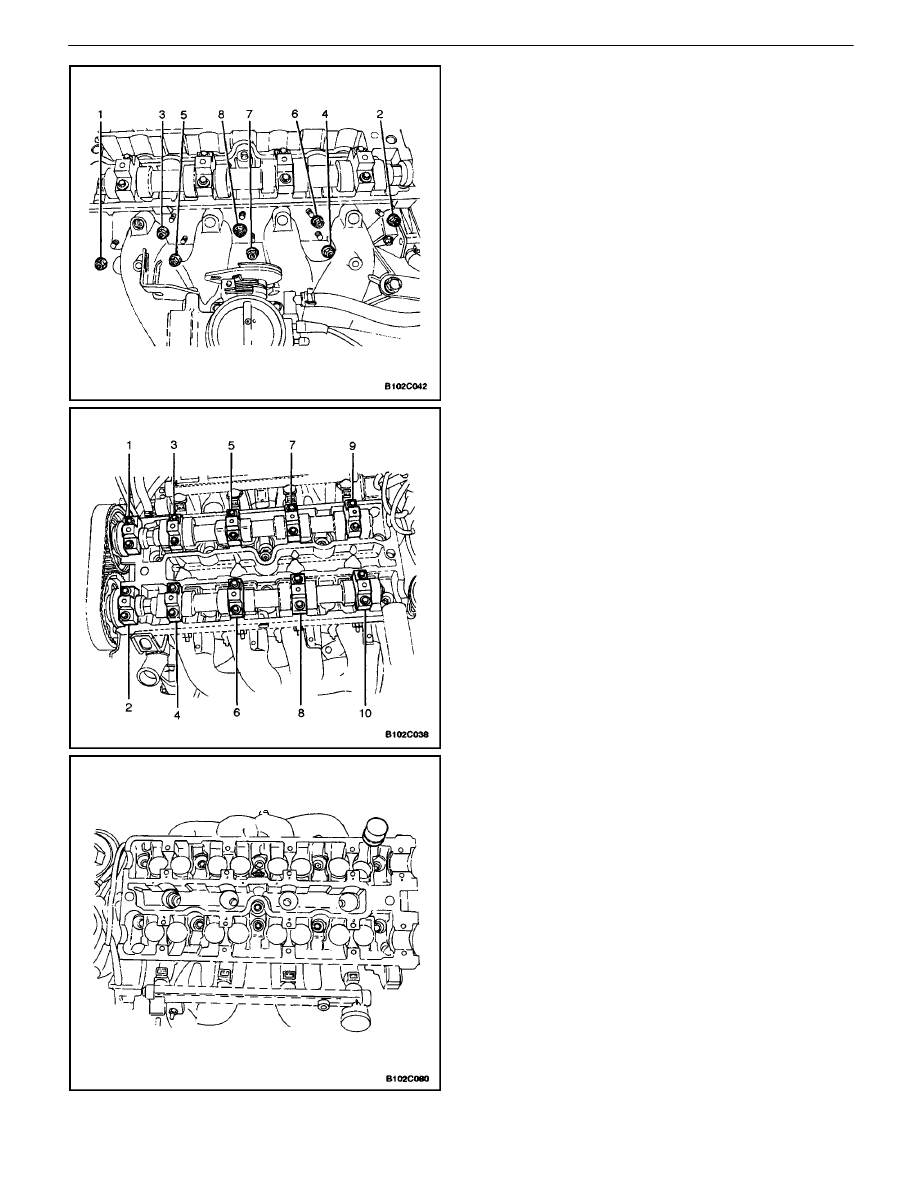
14. Remove the intake manifold retaining nuts and re-
taining bolt in the sequence shown.
15. Remove the intake manifold.
16. Remove the intake manifold gasket.
17. Remove the electronic ignition system (EI System)
ignition coil and EGR mounting bracket bolts.
18. Remove the EI system ignition coil and EGRmount-
ing bracket and ignition wires.
19. Remove the intake manifold studs.
20. Remove the spark plugs.
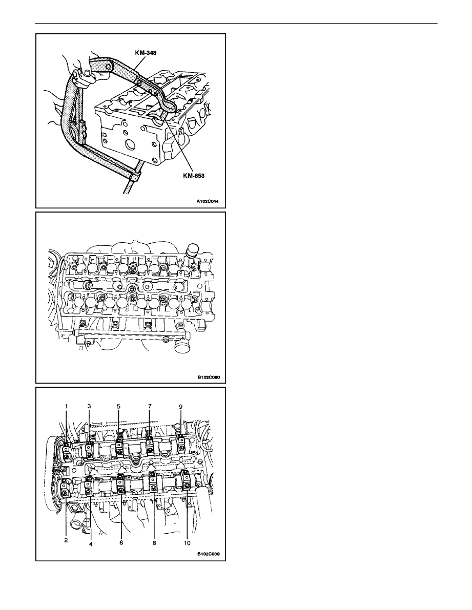
21. Remove the camshaft bearing cap bolts gradually
and in the sequence shown for each camshaft cap.
22. Remove the intake camshaft bearing caps. Main-
tain the correct positions for installation.
23. Remove the intake camshaft.
24. Remove the intake valve lash adjusters.
25. Remove the exhaust camshaft caps. Maintain the
correct positions for installation.
26. Remove the exhaust camshaft.
27. Remove the exhaust valve lash adjusters.

1C – 70
I
DOHC ENGINE MECHANICAL
DAEWOO V–121 BL4
28. Compress the valve springs with the valve spring
compressor KM–348 and the adapter KM–653.
29. Remove the valve retainers.
30. Remove the valve spring compressor KM–348 and
the adapter KM–653.
31. Remove the valve spring caps.
32. Remove the valve springs. Maintain the original
position of the valve springs for installation.
33. Remove the valves. Maintain the original position of
the valves for installation.
34. Remove the valve stem seals.
Cylinder Head Inspection
1. Clean the sealing surfaces.
2. Inspect the cylinder head gasket and mating sur-
faces for leaks, corrosion and blow–by.
3. Inspect the cylinder head for cracks.
4. Inspect the length and width of the cylinder head
using a feeler gauge and a straight edge.
5. Check the sealing surfaces for deformation and
warpage. The cylinder head sealing surfaces must
be flat within 0.025 mm (0.001 inch) maximum.
DOHC ENGINE MECHANICAL 1C – 71
DAEWOO V–121 BL4
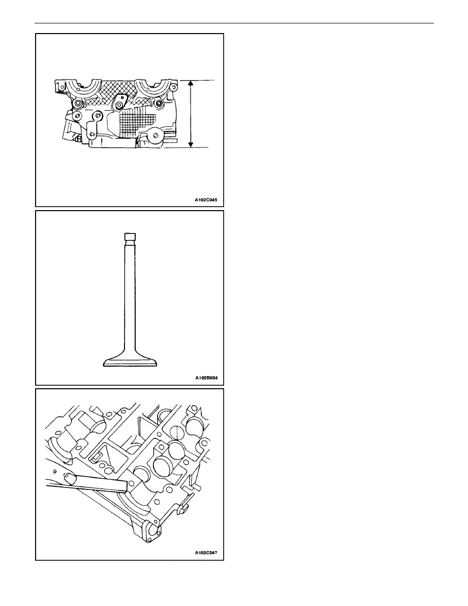
6. Measure the height of the cylinder head from seal-
ing surface to sealing surface. The cylinder head
height should be 133.975 to 134.025 mm (5.274 to
5.276 inches). If the cylinder head height is less
than 133.9 mm (5.271 inches), replace the cylinder
head.
7. Inspect all threaded holes for damage.
8. Inspect valve seats for excessive wear and burned
spots.
Valve Inspection
1. Inspect the valve stem tip for wear.
2. Inspect the valve retainer grooves and the oil seal
grooves for chips and wear.
3. Inspect the valves for burns or cracks.
4. Inspect the valve stem for burrs and scratches.
5. Inspect the valve stem. The valve stem must be
straight.
6. Inspect the valve face for grooving. If the groove is
so deep that refacing the valve would result in a
sharp edge, replace the valve.
7. Inspect the valve spring. If the valve spring ends
are not parallel, replace the valve spring.
8. Inspect the valve spring seating surface of the
valve rotators for wear or gouges. Replace as re-
quired.
Cleaning Procedure
1. Clean the cylinder head.
2. Clean the valve guides.
3. Clean all of the threaded holes.
4. Clean the valves of carbon, oil, and varnish.
1C – 72
I
DOHC ENGINE MECHANICAL
DAEWOO V–121 BL4
Cylinder Head Overhaul
Valve Grind–in
1. Lubricate the valve seat using a fine–grained paste.
2. Lift the valve rhythmically from the seat with a com-
mercially–available valve grinding tool in order to
distribute the paste.
3. Check the contact pattern on the valve head and in
the cylinder head.
4. Clean the valves, the valve guides, and the cylinder
head.
Valve Grind
1. Ensure that there are no crater line burns on the
valve cone.
2. The valve may be reground only two times. Do not
grind the valve stem end.
3. Ensure that the angle at the valve face is 45 de-
grees.
4. Inspect the assembly height of the intake valves
and the exhaust valves.
DOHC ENGINE MECHANICAL 1C – 73
DAEWOO V–121 BL4
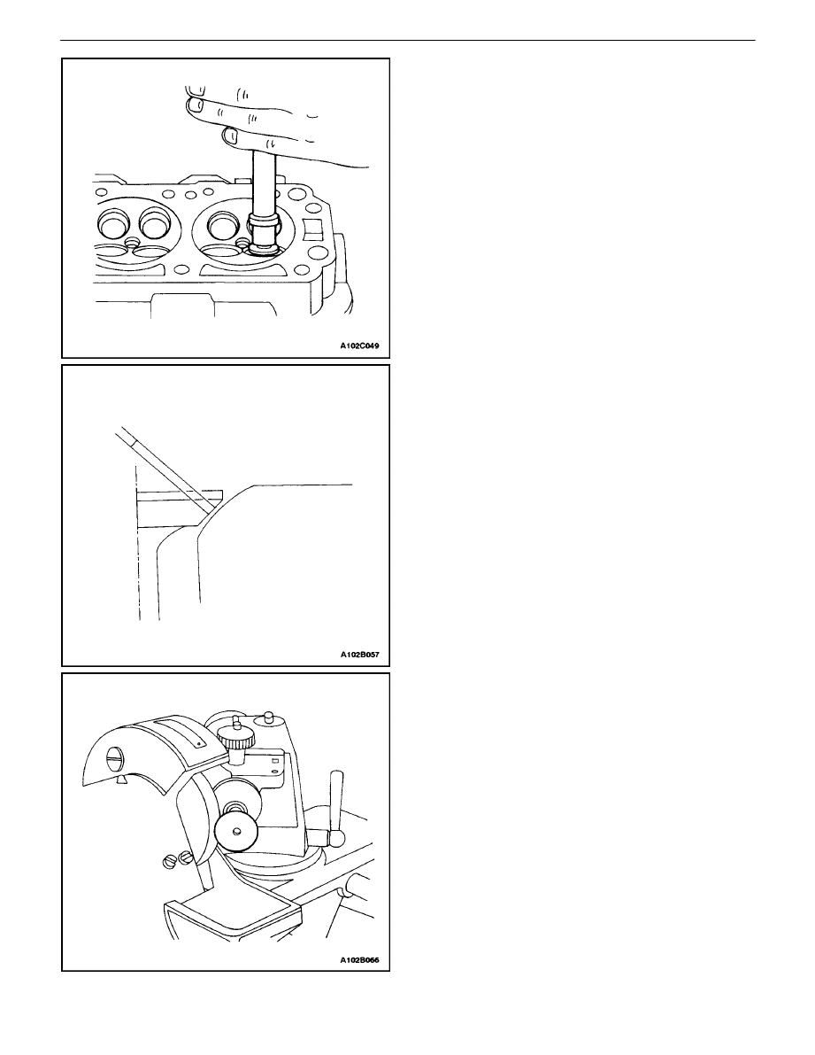
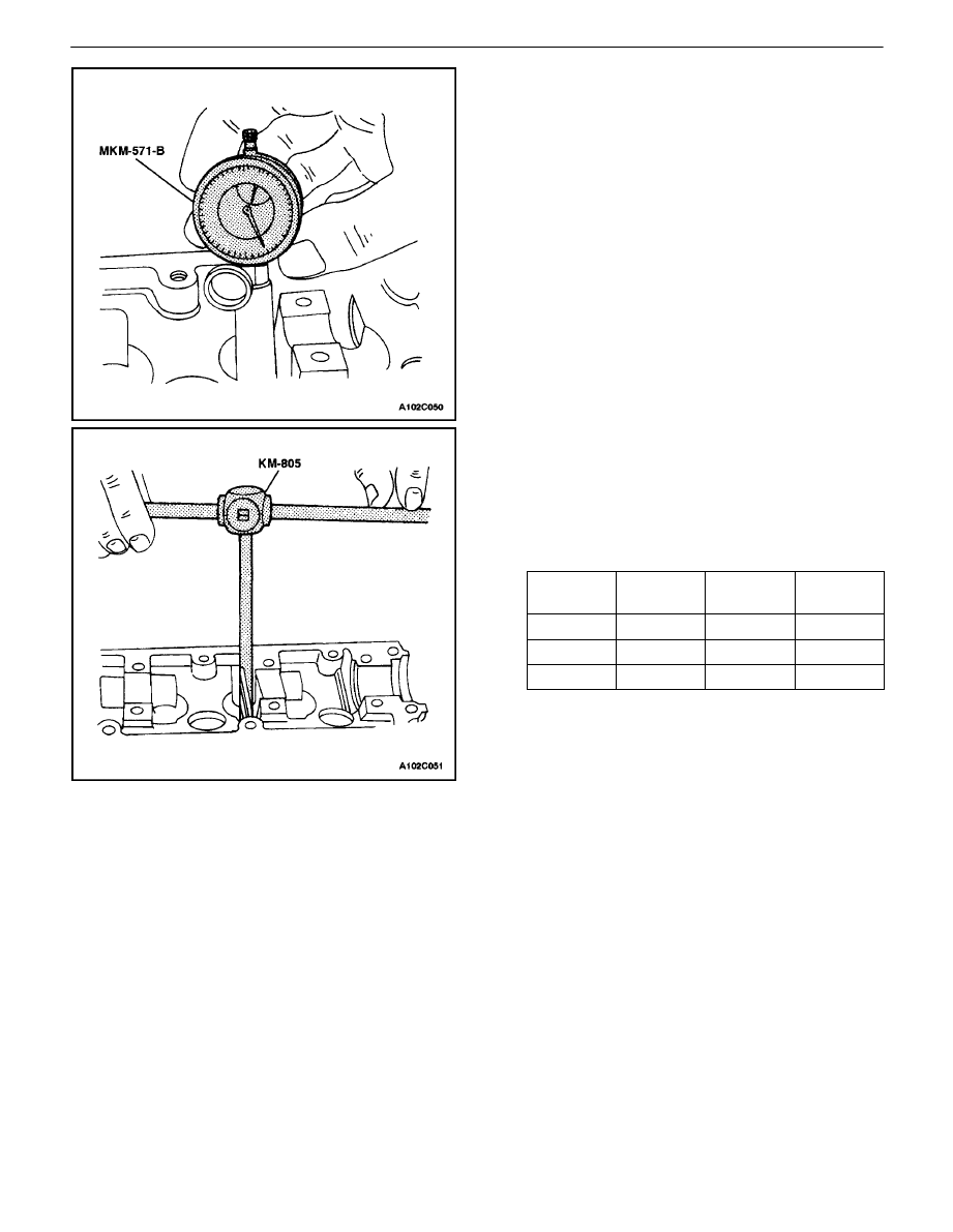
Valve Guide – Ream
1. Measure the diameter of the valve guide using
gauge MKM–571–B and a commercially–available
inside micrometer.
Important : Valve oversizes may already have been fitted
in production.
2. An oversize service code is on the valve guide and
the valve stem end. The following table gives the
correct size, reamer, and production code for each
service.
Size
Reamer
Productio
n Code
Service
Code
Normal
–
–
K
0.075
KM–805
1
K1
0.150
2
K2
3. Ream the valve guide from the upper side of the
cylinder head to the next oversize.
4. After reaming, cross out the code and emboss the
valve guide with the new code.
1C – 74
I
DOHC ENGINE MECHANICAL
DAEWOO V–121 BL4
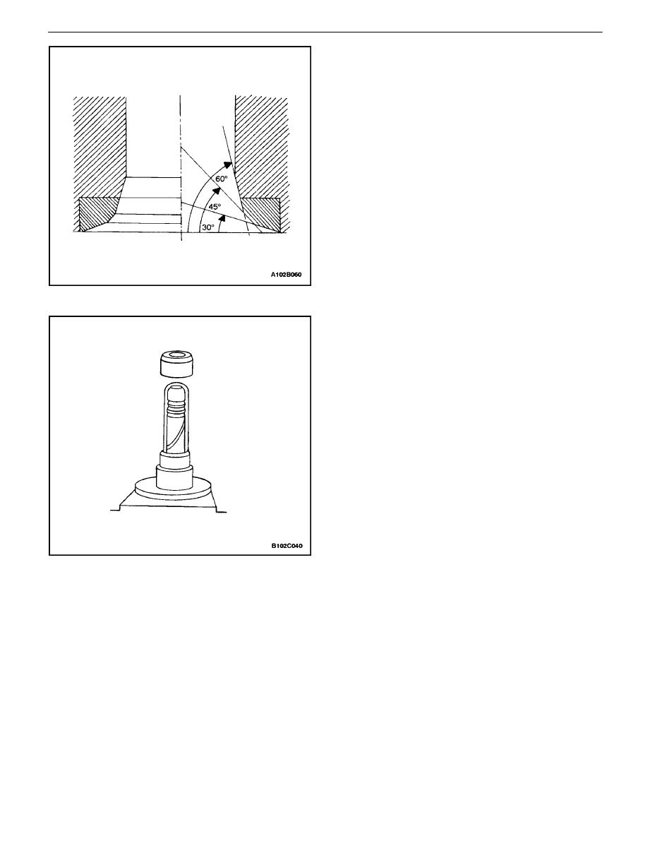
Valve Seat – Cut
1. Place the cylinder head on wooden blocks.
2. Cut the intake and the exhaust valve seats using
the guide drift KM–340–7 as follows:
S
Valve seat – A 45–degree surface using the cut-
ter KM–340–13.
S
Upper correction angle – A 30–degree surface
using the cutter KM–340–13.
S
Lower correction angle – A 60–degree surface
using the cutter KM–340–26.
3. Clean the chippings from the cylinder head.
4. Inspect the dimension for the valve seat width.
S
Intake: 1.2 to 1.4 mm (0.047 to 0.055 inch).
S
Exhaust: 1.4 to 1.8 mm (0.055 to 0.070 inch).
5. Inspect the assembly height of the intake valves
and the exhaust valves. If the dimension is exceed-
ed, install new valves. Inspect the assembly height
of the intake valves and the exhaust valves again. If
the valve assembly height is still too large despite
replacing the valves, replace the cylinder head.
Assembly Procedure
1. Coat the valve stems with engine oil.
2. Insert the valves in the cylinder head in their origi-
nal positions.
3. Insert the valve spring seats.
4. Push the accompanying assembly sleeve onto the
valve stem.
5. Insert the new valve stem seat.
6. Carefully drive the valve stem seal onto the stop
with light taps.
7. Install the valve springs in their original positions.
8. Install the valve spring caps.
DOHC ENGINE MECHANICAL 1C – 75
DAEWOO V–121 BL4
9. Compress the valve springs with the valve spring
compressor KM–348 and adapter KM–653.
10. Install the valve retainers.
11. Remove the valve spring compressor KM–348 and
adapter KM–653.
12. Lubricate the valve lash adjusters with engine oil.
13. Install the valve lash adjusters.
14. Install the intake camshaft.
15. Install the intake camshaft bearing caps in their
original positions.
16. Install the exhaust camshaft.
17. Install the exhaust camshaft bearing caps in their
original positions.
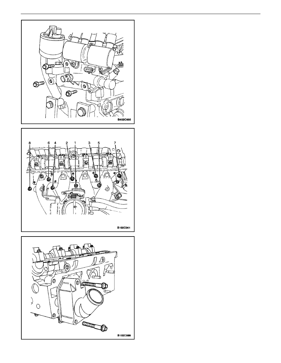
18. Install the camshaft bearing cap bolts.
19. Tighten the camshaft bearing cap bolts gradually
and in the sequence shown for each camshaft cap.
Tighten
Tighten the camshaft bearing cap bolts to 8 N
S
m (71
lb–in).
1C – 76
I
DOHC ENGINE MECHANICAL
DAEWOO V–121 BL4
20. Install the spark plugs.
Tighten
Tighten the spark plugs to 20 N
S
m (15 lb–ft).
21. Install the EI system ignition coil and EGR mount-
ing bracket.
22. Install the EI system ignition coil and EGR mount-
ing bracket bolts.
Tighten
Tighten the EI system ignition coil and EGR mounting
bracket bolts to 25 N
S
m (18 lb–ft).
23. Install the intake manifold studs.
24. Install the intake manifold gasket.
25. Install the intake manifold.
26. Install the intake manifold retaining nuts and retain-
ing bolt in the sequence shown.
Tighten
Tighten the intake manifold retaining nuts and retain-
ing bolt to 22 N
S
m (16 lb–ft).
27. Install the fuel rail assembly. Refer to Section 1F,
Engine Controls.
28. Install the thermostat housing assembly.
29. Install the thermostat housing mounting bolts.
Tighten
Tighten the thermostat housing mounting bolts to 15
N
S
m (11 lb–ft).
30. Install the coolant bypass housing and mounting
bolts.
Tighten
Tighten the coolant bypass housing and mounting
bolts to 15 N
S
m (11 lb–ft).
31. Install the camshaft position sensor.
Tighten
Tighten the camshaft position sensor bolts to 12 N
S
m
(106 lb–in).
DOHC ENGINE MECHANICAL 1C – 77
DAEWOO V–121 BL4
32. Install the exhaust manifold studs.
33. Install the exhaust manifold gasket.
34. Install the exhaust manifold.
35. Install the exhaust manifold retaining nuts in the
sequence shown.
Tighten
Tighten the exhaust manifold retaining nuts to 15 N
S
m
(11 lb–ft).
36. Install the exhaust manifold heat shield.
37. Install the exhaust manifold heat shield bolts.
Tighten
Tighten the exhaust manifold heat shield bolts to 8
N
S
m (71 lb–in).
38. Install the cylinder head with the intake manifold
and the exhaust manifold attached. Refer to ”Cylin-
der Head and Gasket” in this section.
CRANKSHAFT
Tools Required
KM–412 Engine Overhaul Stand
KM–470–B Angular Torque Gauge
KM–635 or J–36972 Crankshaft Rear Oil Seal Installer
Notice : Take extreme care to prevent any scratches,
nicks, or damage to the camshafts.
Disassembly Procedure
1. Remove the engine. Refer to ”Engine” in this sec-
tion.
2. Remove the flywheel or flexible plate bolts.
3. Remove the flywheel or the flexible plate.
4. Remove the crankshaft rear oil seal.
5. Mount the engine assembly on the engine overhaul
stand KM–412.
1C – 78
I
DOHC ENGINE MECHANICAL
DAEWOO V–121 BL4
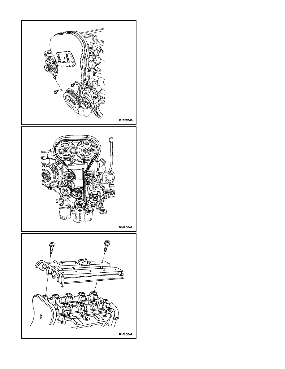
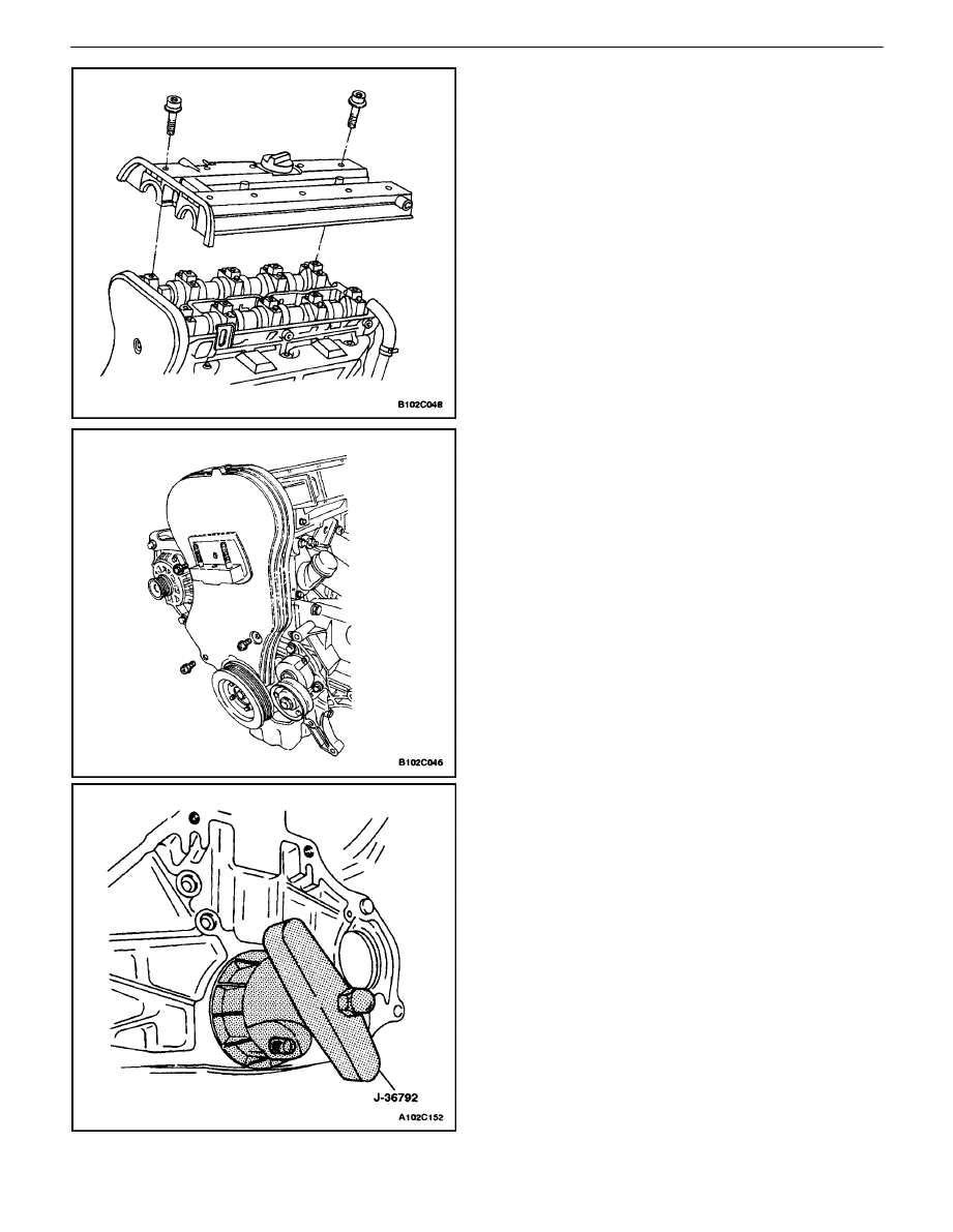
6. Remove the front timing belt cover bolts.
7. Remove the front timing belt cover.
8. Remove the crankshaft pulley bolts.
9. Remove the crankshaft pulley.
10. Loosen the timing belt automatic tensioner bolt.
11. Rotate the timing belt automatic tensioner hex–key
clockwise to release the tension.
12. Remove the timing belt idler pulley bolt and nut.
13. Remove the timing belt idler pulleys.
14. Remove the timing belt.
15. Remove the engine mount retaining bolts.
16. Remove the engine mount.
17. Disconnect the crankcase breather tubes from the
valve cover.
18. Remove the spark plug cover bolts.
19. Remove the spark plug cover.
20. Disconnect the ignition wires from the spark plugs.
21. Remove the valve cover bolts.
22. Remove the valve cover washers.
23. Remove the valve cover and the valve cover gas-
ket.
DOHC ENGINE MECHANICAL 1C – 79
DAEWOO V–121 BL4
Notice : Take extreme care to prevent any scratches,
nicks or damage to the camshafts.
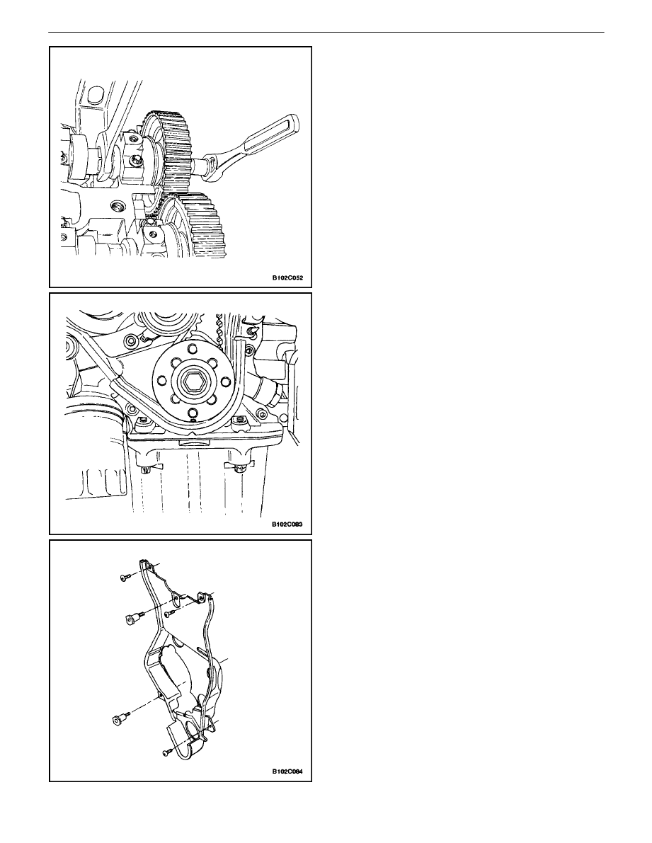
24. While holding the intake camshaft firmly in place,
remove the intake camshaft bolt.
25. Remove the intake camshaft gear.
26. While holding the exhaust camshaft firmly in place,
remove the exhaust camshaft bolt.
27. Remove the exhaust camshaft gear.
28. Remove the crankshaft timing belt gear.
29. Remove the rear timing belt cover bolts and cover.
1C – 80
I
DOHC ENGINE MECHANICAL
DAEWOO V–121 BL4
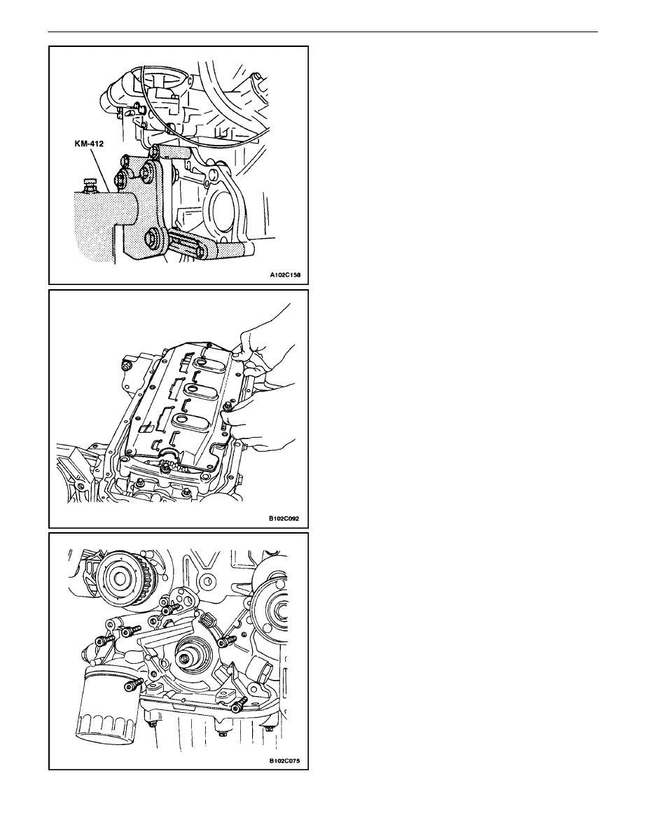
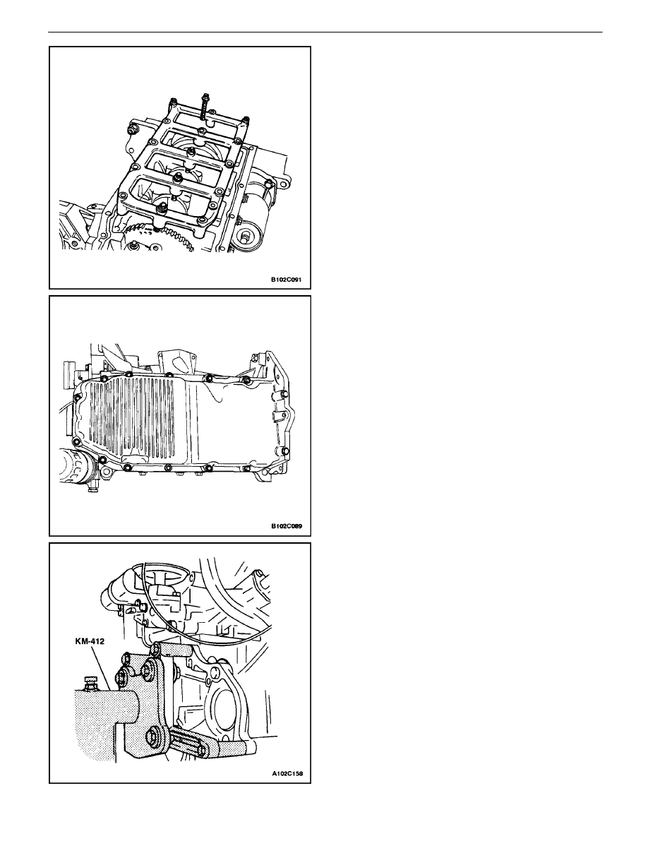
30. Rotate the engine on the engine overhaul stand
KM–412.
31. Remove the oil pan retaining bolts.
32. Remove the oil pan.
33. Remove the oil pump/pickup tube bolts.
34. Remove the oil pump/pickup tube.
35. Remove the lower block support bracket/splash
shield bolts.
36. Remove the splash shield.
37. Remove the lower block support bracket bolts.
38. Remove the lower block support bracket.
39. Remove the oil pump retaining bolts.
40. Remove the oil pump.
DOHC ENGINE MECHANICAL 1C – 81
DAEWOO V–121 BL4
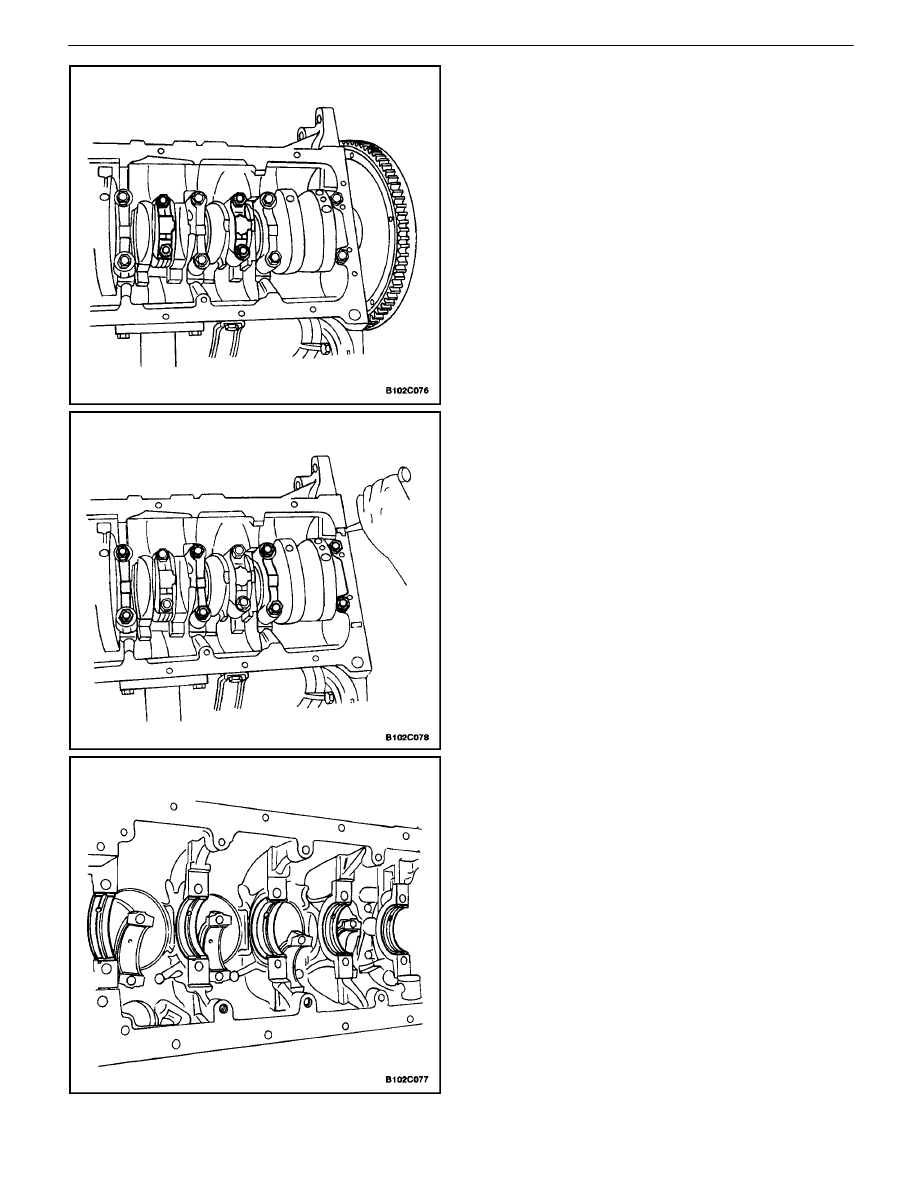
41. Mark the order of the connecting rod bearing caps.
42. Remove the connecting rod bearing cap bolts for all
of the pistons.
43. Remove the connecting rod bearing caps and the
lower connecting rod bearings.
44. Mark the order of the crankshaft bearing caps.
45. Remove the crankshaft bearing cap bolts.
46. Remove the crankshaft bearing caps and the lower
crankshaft bearings.
47. Remove the crankshaft.
48. Clean any necessary parts.
Assembly Procedure
1. Coat the crankshaft bearings with engine oil.
2. If replacing the crankshaft, transfer the pulse pick–
up sensor disc to the new crankshaft.
1C – 82
I
DOHC ENGINE MECHANICAL
DAEWOO V–121 BL4
3. Install the crankshaft.
4. Install the lower crankshaft bearings in the bearing
caps.
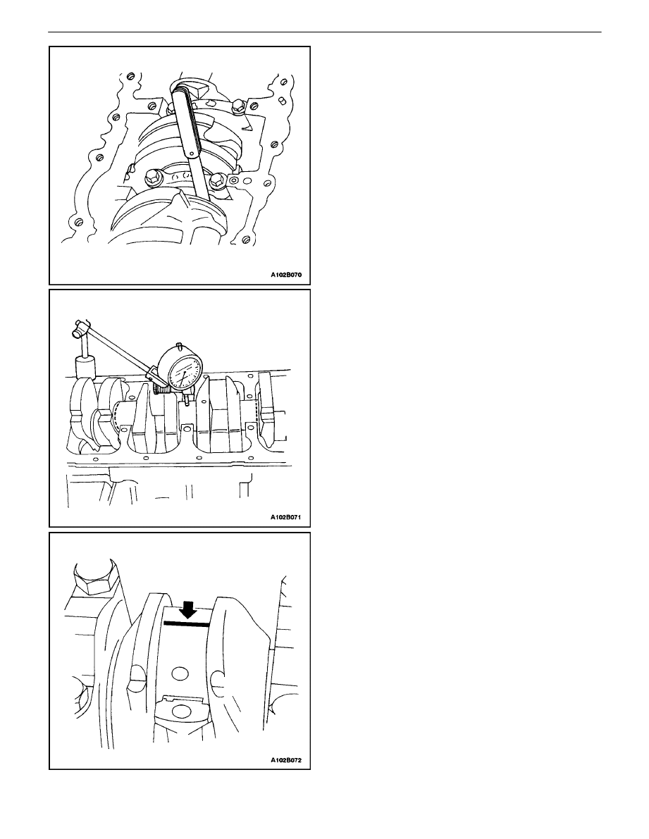
5. Inspect the crankshaft end play with the crankshaft
bearings installed.
6. Check for permissible crankshaft end play. Refer
to”Engine Specifications”in this section.
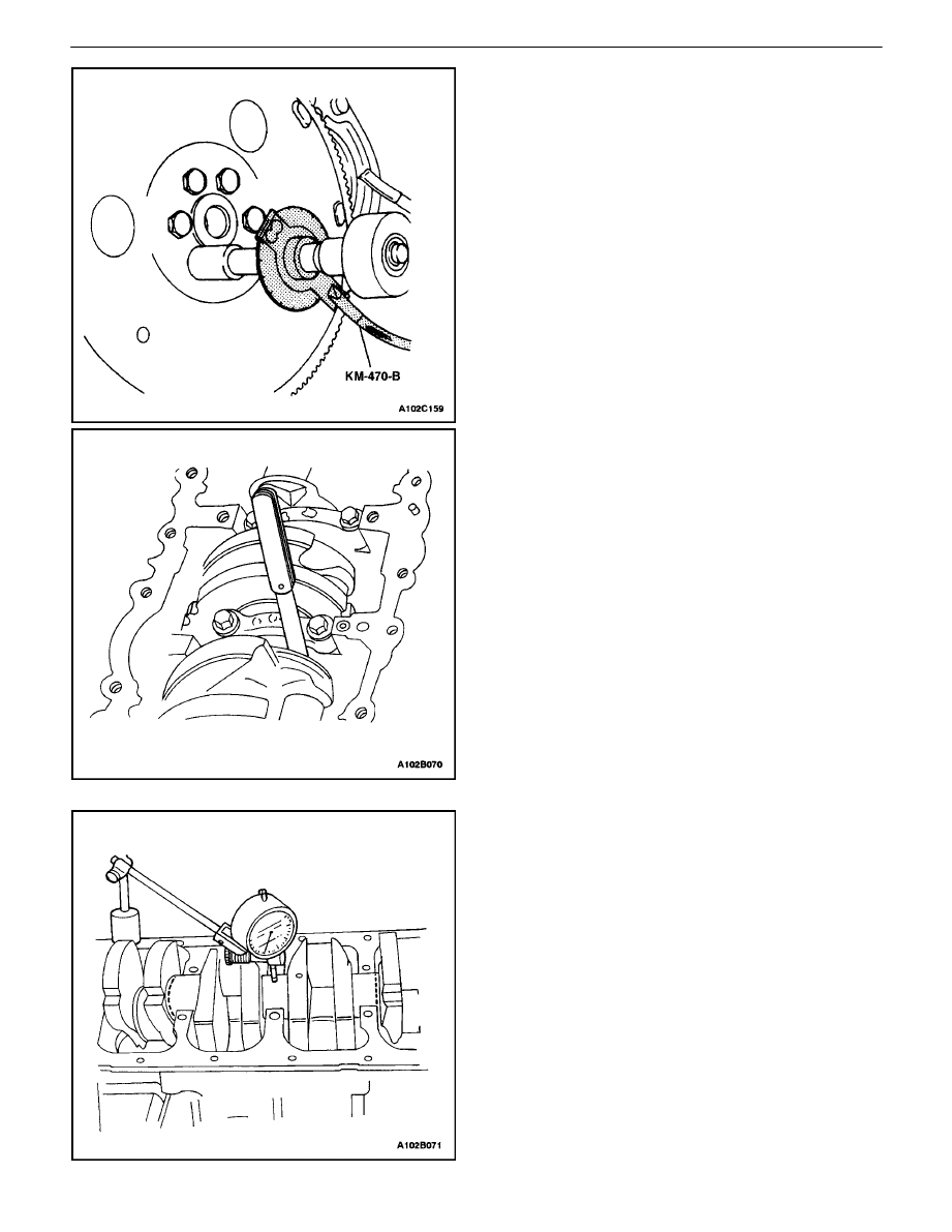
7. With the crankshaft mounted on the front and rear
crankshaft bearings, check the middle crankshaft
journal for permissible out–of–round (runout). Refer
to ”Engine Specifications”in this section.
Important : Grease the crankshaft journals and lubricate
the crankshaft bearings slightly so that the plastic gauging
thread does not tear when the crankshaft bearing caps are
removed.
8. Inspect all of the crankshaft bearing clearances us-
ing a commercially available plastic gauging (ductile
plastic threads).
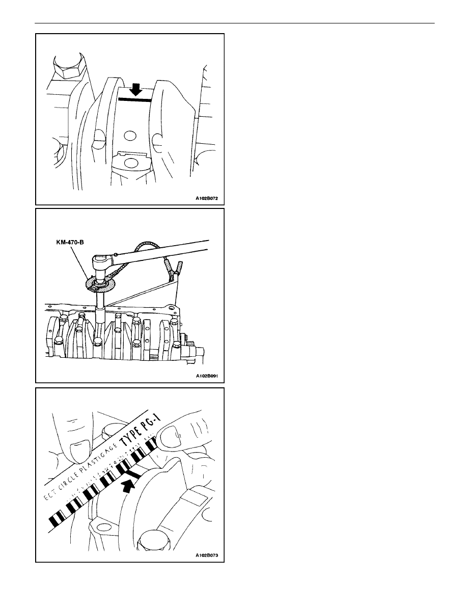
9. Cut the plastic gauging threads to the length of the
bearing width. Lay them axially between the crank-
shaft journals and the crankshaft bearings.
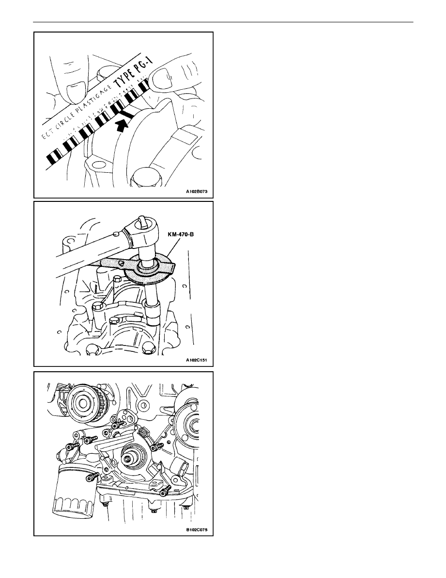
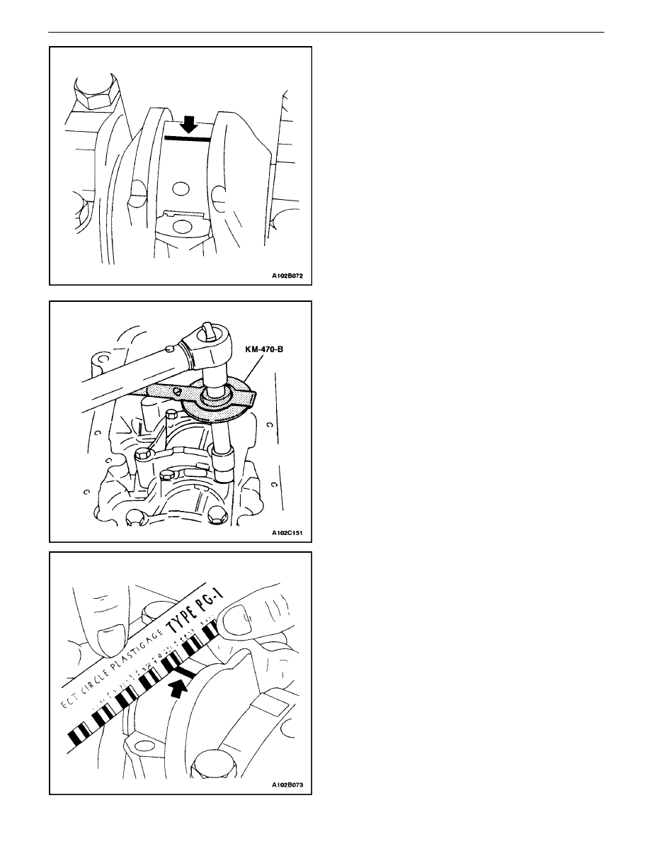
10. Install the crankshaft bearing caps and the bolts.
Tighten
Tighten the crankshaft bearing cap bolts to 50 N
S
m
(26 lb–ft). Use the angular torque gauge, KM–470–B,
to tighten the crankshaft bearings +45 degrees +
another 15 degrees.
DOHC ENGINE MECHANICAL 1C – 83
DAEWOO V–121 BL4
11. Remove the crankshaft bearing cap bolts and the
caps.
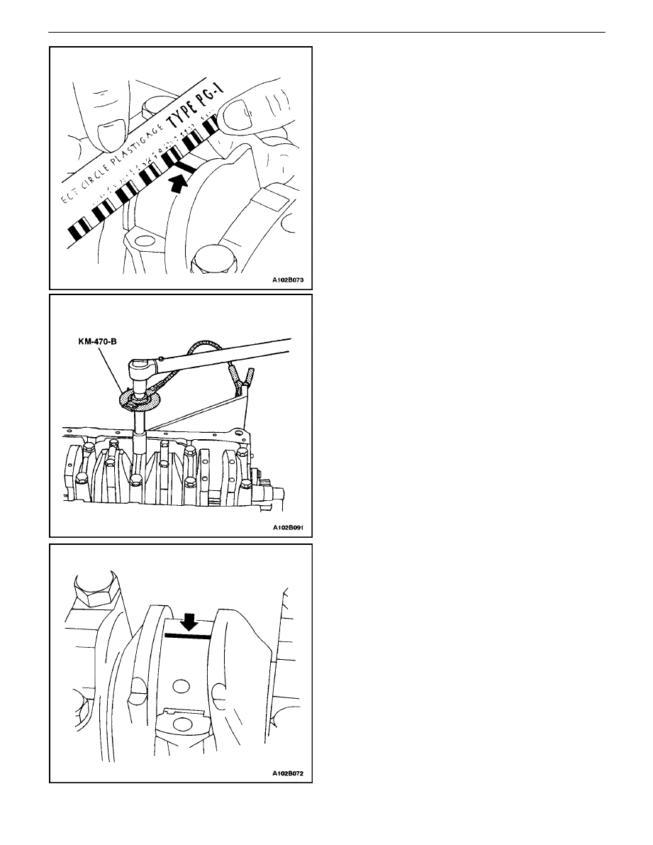
12. Measure the width of the flattened plastic thread of
the plastic gauging using a ruler. (Plastic gauging is
available for different tolerance ranges.)
13. Inspect the bearing clearance for permissible toler-
ance ranges. Refer to ”Engine Specifications”in this
section.
14. Apply a bead of adhesive sealing compound to the
grooves of the crankshaft bearing caps.
15. Install the crankshaft bearing caps to the engine
block.
16. Tighten the crankshaft bearing caps using new
bolts.
Tighten
Tighten the crankshaft bearing cap bolts to 15 N
S
m
(26 lb–ft). Use the angular torque gauge, KM–470–B,
to tighten the crankshaft bearings +45 degrees +
another 15 degrees.
Important : Grease the connecting rod journals and lubri-
cate the connecting rod bearings slightly so that the plastic
gauging thread does not tear when the connecting rod
bearing caps are removed.
17. Inspect all of the connecting rod bearing clearances
using a commercially available plastic gauging
(ductile plastic threads).
18. Cut the plastic gauging threads to the length of the
connecting rod bearing width. Lay them axially be-
tween the connecting rod journals and the connect-
ing rod bearings.
19. Install the connecting rod bearing caps.
Tighten
Tighten the connecting rod bearing cap bolts to 35
N
S
m (26 lb–ft). Use the angular torque gauge
KM–470–B to tighten the connecting rod bearing cap
bolts to +45 degrees plus one turn of 15 degrees.
1C – 84
I
DOHC ENGINE MECHANICAL
DAEWOO V–121 BL4
20. Remove the connecting rod bearing caps.
21. Measure the width of the flattened plastic thread of
the plastic gauging using a ruler. (Plastic gauging is
available for different tolerance ranges.)
22. Inspect the bearing clearance for permissible toler-
ance ranges. Refer to ”Engine Specifications”in this
section.
23. Install the connecting rod bearing caps to the con-
necting rods.
24. Tighten the connecting rod bearing caps using new
bolts.
Tighten
Tighten the connecting rod bearing cap bolts to 35
N
S
m (26 lb–ft). Use the angular torque gauge,
KM–470–B, to tighten the connecting rod cap bolts to
+45 degrees plus one turn of 15 degrees.
25. Install the oil pump.
26. Install the oil pump retaining bolts.
Tighten
Tighten the oil pump retaining bolts to 10 N
S
m (89 lb–
in).
DOHC ENGINE MECHANICAL 1C – 85
DAEWOO V–121 BL4
27. Install the lower block support bracket and bolts.
Tighten
Tighten the lower block support bolts to 35 N
S
m (26
lb–ft).
28. Install the lower block support bracket splash shield
and bolts.
Tighten
Tighten the lower block support bracket and splash
shield bolts to 35 N
S
m (26 lb–ft).
29. Install the oil pump/pick–up tube.
30. Install the oil pump/pick–up tube bolts.
Tighten
Tighten the oil pump/pick–up tube bolts to 10 N
S
m (89
lb–in).
31. Install the oil pan gasket to the oil pan.
32. Install the oil pan.
Important : Install the oil pan within 5 minutes after apply-
ing the liquid gasket to the oil pan.
33. Install the oil pan retaining bolts.
Tighten
Tighten the oil pan retaining bolts to 10 N
S
m (89 lb–in).
34. Rotate the engine on the engine overhaul stand
KM–412.
1C – 86
I
DOHC ENGINE MECHANICAL
DAEWOO V–121 BL4
35. Install the rear timing belt cover.
36. Install the rear timing belt cover bolts.
Tighten
Tighten the rear timing belt cover bolts to 7 N
S
m (62
lb–in).
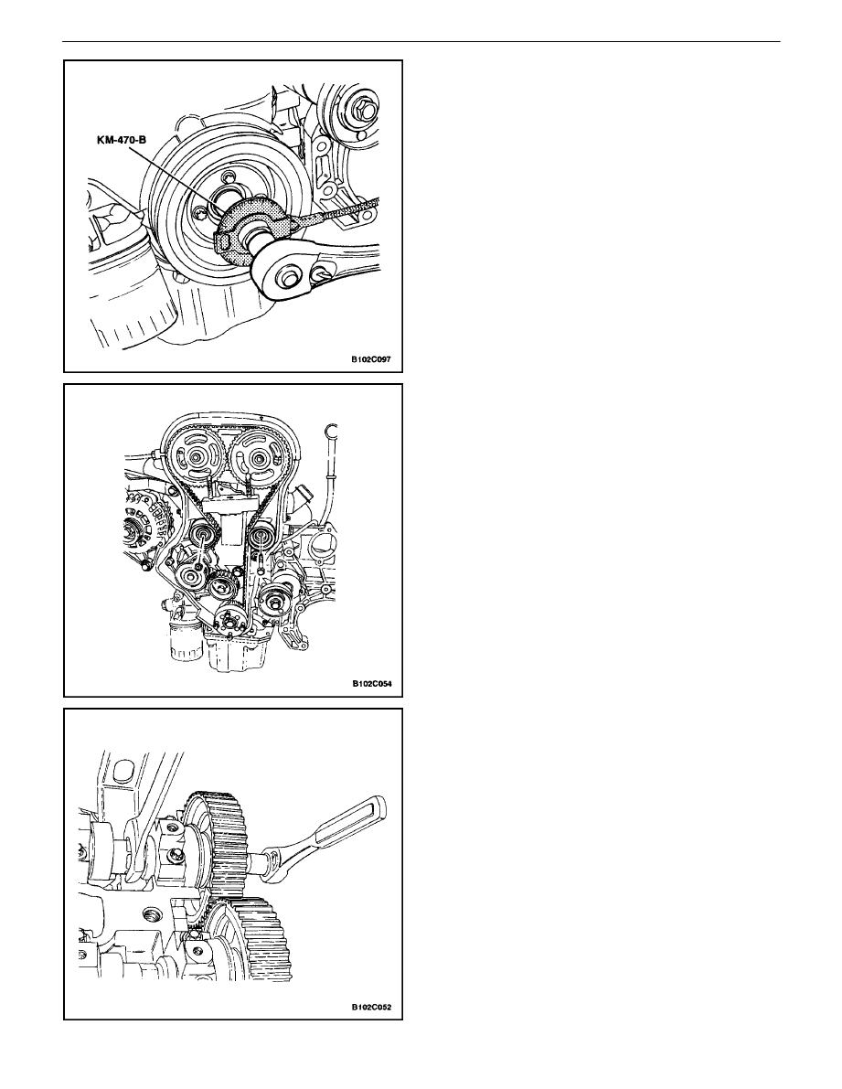
37. Install the crankshaft timing belt drive gear and the
bolt.
Tighten
Tighten the crankshaft timing belt drive gear bolt to
135 N
S
m (100 lb–ft) plus 30
³
to 10
³
using the torque
angular gauge KM–470–B.
38. Install the engine mount and the retaining bolts.
Tighten
Tighten the engine mount retaining bolts to 60 N
S
m
(44 lb–ft).
39. Install the timing belt automatic tensioner.
40. Install the timing belt automatic tensioner bolts.
Tighten
Tighten the timing belt automatic tensioner bolts to 25
N
S
m (18 lb–ft).
41. Install the timing belt idler pulley.
42. Install the timing belt idler pulley bolt and nut.
Tighten
Tighten the timing belt idler pulley bolt to 25 N·m (18
lb–ft).
Tighten
Tighten the timing belt idler pulley nut to 25 N
S
m (18
lb–ft).
Notice : Take extreme care to prevent any scratches,
nicks or damage to the camshafts.
43. Install the intake camshaft gear.
44. Install the intake camshaft gear bolt while holding
the intake camshaft firmly in place.
Tighten
Tighten the intake camshaft gear bolt to 50 N
S
m (37
lb–ft).
45. Install the exhaust camshaft gear.
46. Install the exhaust camshaft gear bolt while holding
the exhaust camshaft firmly in place.
Tighten
Tighten the exhaust camshaft gear bolt to 50 N
S
m (37
lb–ft). Using the angular torque gauge KM–470–B,
tighten the intake and the exhaust camshaft gear
bolts another 60 degrees plus 15 degrees.
DOHC ENGINE MECHANICAL 1C – 87
DAEWOO V–121 BL4
47. Install the timing belt. Refer to ”Timing Belt” in this
section.
48. Adjust the timing belt tension. Refer to ”Timing Belt
Check and Adjust” in this section.
49. Apply a small amount of gasket sealant to the cor-
ners of the front camshaft caps and to the top of
the rear valve cover to cylinder head seal.
50. Install the valve cover and the valve cover gasket.
51. Install the valve cover washers.
52. Install the valve cover bolts.
Tighten
Tighten the valve cover bolts to 8 N
S
m (71 lb–in).
53. Connect the ignition wires to the spark plugs.
54. Install the spark plug cover.
55. Install the spark plug cover bolts.
Tighten
Tighten the spark plug cover bolts to 8 N
S
m (71 lb–in).
56. Connect the crankcase breather tube to the valve
cover.
57. Install the front timing belt cover.
58. Install the front timing belt cover bolts.
Tighten
Tighten the front timing belt cover bolts to 6 N
S
m (53
lb–in).
59. Install the engine lifting device.
60. Remove the engine from the engine overhaul stand
KM–412.
61. Install a new crankshaft rear oil seal using installer
J–36972 (or KM–635).
1C – 88
I
DOHC ENGINE MECHANICAL
DAEWOO V–121 BL4
62. Install the flywheel or flexible plate.
63. Install the flywheel or the flexible plate bolts.
Tighten
Tighten the flywheel bolts to 65 N
S
m (48 lb–ft). Use
the angular torque gauge KM–470–B to tighten the
flywheel bolts to 30 degrees plus 15 degrees. For the
automatic transmission, tighten the flexible plate bolts
to 65 N
S
m (48 lb–ft).
64. Install the engine. Refer to ”Engine”in this section.
CRANKSHAFT BEARINGS AND
CONNECTING ROD BEARINGS –
GAUGING PLASTIC
Tools Required
KM–470–B Angular Torque Gauge
Inspection Procedure – Crankshaft
1. Coat the crankshaft bearings with engine oil.
2. Install the upper crankshaft bearings into the engine
block crankshaft journals.
3. Install the lower crankshaft bearings into the crank-
shaft bearing caps.
4. Install the crankshaft.
5. Inspect the crankshaft end play with the crankshaft
bearings installed.
6. Check for permissible crankshaft end play. Refer to
”Engine Specifications”in this section.
7. With the crankshaft mounted on the front and rear
crankshaft bearings, check the middle crankshaft
journal for permissible out–of–round (runout). Refer
to ”Engine Specifications”in this section.
DOHC ENGINE MECHANICAL 1C – 89
DAEWOO V–121 BL4
Important : Grease the crankshaft journals and lubricate
the crankshaft bearings slightly so that the plastic gauging
thread does not tear when the crankshaft bearing caps are
removed.
8. Inspect all of the crankshaft bearing clearances us-
ing a commercially available plastic gauging (ductile
plastic threads).
9. Cut the plastic gauging threads to the length of the
bearing width. Lay them axially between the crank-
shaft journals and the crankshaft bearings.
10. Install the crankshaft bearing caps.
11. Install the crankshaft bearing cap bolts.
Tighten
Tighten the crankshaft bearing cap bolts to 50 N
S
m
(37 lb–ft). Using the angular torque gauge
KM–470–B, tighten the crankshaft bearing cap bolts
to +45 degrees +15 degrees.
12. Remove the crankshaft bearing caps.
13. Measure the width of the flattened plastic thread of
the plastic gauging using a ruler. (Plastic gauging is
available for different tolerance ranges.)
14. Inspect the bearing clearances for permissible toler-
ance ranges. Refer to ”Engine Specifications”in this
section.
1C – 90
I
DOHC ENGINE MECHANICAL
DAEWOO V–121 BL4
Inspection Procedure – Connecting Rods
1. Coat the connecting rod bearings with engine oil.
2. Install the upper connecting rod bearings into the
connecting rod journals.
3. Install the lower connecting rod bearings into the
connecting rod bearing caps.
Important : Grease the connecting rod journals and lubri-
cate the connecting rod bearings slightly so that the plastic
gauging thread does not tear when the connecting rod
bearing caps are removed.
4. Inspect all of the connecting rod bearing clearances
using a commercially available plastic gauging
(ductile plastic threads).
5. Cut the plastic gauging threads to the length of the
bearing width. Lay them axially between the con-
necting rod journals and the connecting rod bear-
ings.
6. Install the connecting rod bearing caps.
7. Install the connecting rod bearing cap bolts.
Tighten
Tighten the connecting rod cap bolts to 35 N
S
m (26 lb–
ft). Using the angular torque gauge KM–470–B, tight-
en the connecting rod cap bolts to +45 degrees plus
one turn of 15 degrees.
8. Remove the connecting rod bearing caps.
9. Measure the width of the flattened plastic thread of
the plastic gauging using a ruler. (Plastic gauging is
available for different tolerance ranges.)
10. Inspect the bearing clearance for permissible toler-
ance ranges. Refer to ”Engine Specifications”in this
section.
Wyszukiwarka
Podobne podstrony:
ENGINE MECHANICAL 1C 12 43
ENGINE MECHANICAL 1C 91
DOHC ENGINE MECHANICAL 1C 11
M31b1 SOHC Engine Mechanical
14 Engine Mechanical
14 Engine Mechanical
ENGINE MECHANICAL
M31b1 SOHC Engine Mechanical
03 2007 Engine Mechanical
ENGINE MECHANICAL Service data
14 Engine Mechanical
Introduction to Engineering Mechanics Overview
14 Engine Mechanical
Diesel engine, Akademia Morska -materiały mechaniczne, szkoła, Mega Szkoła, Szkoła moje
Mechanika 81-90, Semestr II, Mechanika techniczna
Fundamentals Handbook Mechanical Science Doe Diesel Engines, Heat Exchangers, Pumps, Valves(1)
1C Warunki sprawdzane, POLITECHNIKA ŚLĄSKA Wydział Mechaniczny-Technologiczny - MiBM POLSL, Inżynier
więcej podobnych podstron