1C – 12
I
DOHC ENGINE MECHANICAL
DAEWOO V–121 BL4
MAINTENANCE AND REPAIR
ON–VEHICLE SERVICE
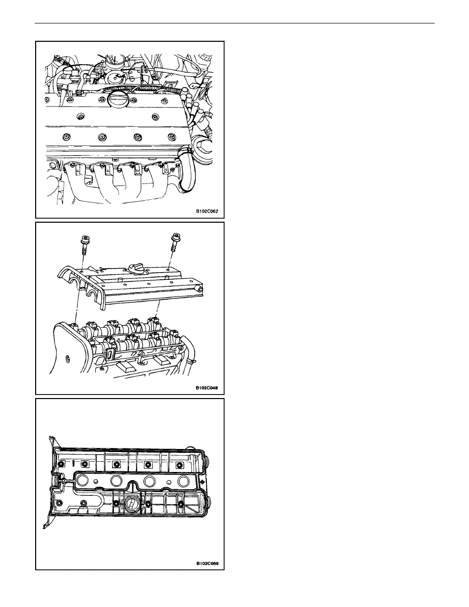
VALVE COVER
Removal Procedure
1. Disconnect the negative battery cable.
2. Disconnect the breather tube from the valve cover.
3. Disconnect the camshaft position sensor.
4. Disconnect all of the necessary vacuum lines.
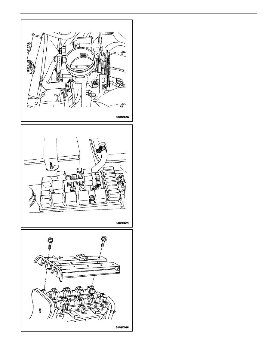
5. Remove the spark plug cover bolts.
6. Remove the spark plug cover.
7. Disconnect the ignition wires from the spark plugs.
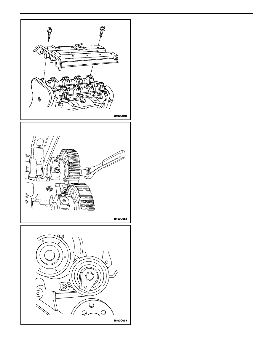
8. Remove the valve cover bolts.
9. Remove the valve cover washers.
10. Remove the valve cover.
11. Remove the valve cover gasket from the valve cov-
er.
DOHC ENGINE MECHANICAL 1C – 13
DAEWOO V–121 BL4
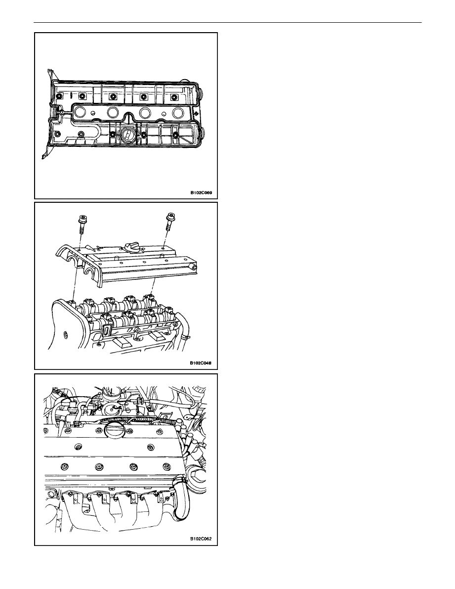
Installation Procedure
1. Apply a small amount of gasket sealant to the cor-
ners of the front camshaft caps and the top of the
rear valve cover–to–cylinder head seal.
2. Install the new valve cover gasket to the valve cov-
er.
3. Install the valve cover.
4. Install the valve cover washers.
5. Install the valve cover bolts.
Tighten
Tighten the valve cover bolts to 8 N
S
m (71 lb–in).
6. Connect the camshaft position sensor.
7. Connect the ignition wires to the spark plugs.
8. Install the spark plug cover.
9. Install the spark plug cover bolts.
Tighten
Tighten the spark plug cover bolts to 3 N
S
m (27 lb–in).
10. Connect all of the necessary vacuum lines.
11. Connect the breather tube to the valve cover.
12. Connect the negative battery cable.
1C – 14
I
DOHC ENGINE MECHANICAL
DAEWOO V–121 BL4
CYLINDER HEAD AND GASKET
Tools Required
KM–470–B Angular Torque Gauge
J–28467–B Engine Assembly Lift Support
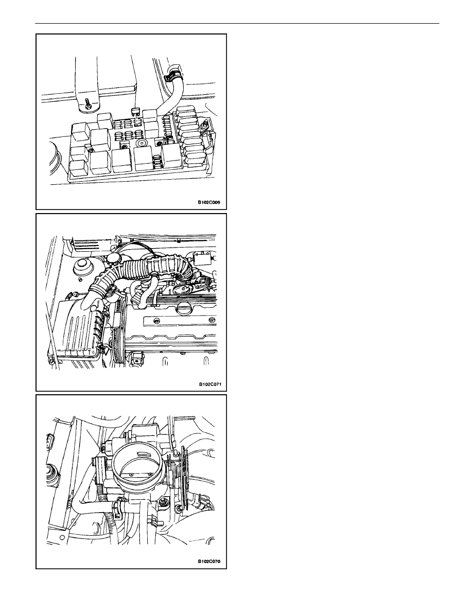
Removal Procedure
1. Remove the fuel pump fuse.
2. Start the engine. After it stalls, crank the engine for
10 seconds to rid the fuel system of fuel pressure.
3. Disconnect the negative battery cable.
4. Disconnect the powertrain control module
(PCM)/engine control module (ECM) ground termi-
nal.
5. Drain the engine coolant. Refer to Section 1D, En-
gine Cooling.
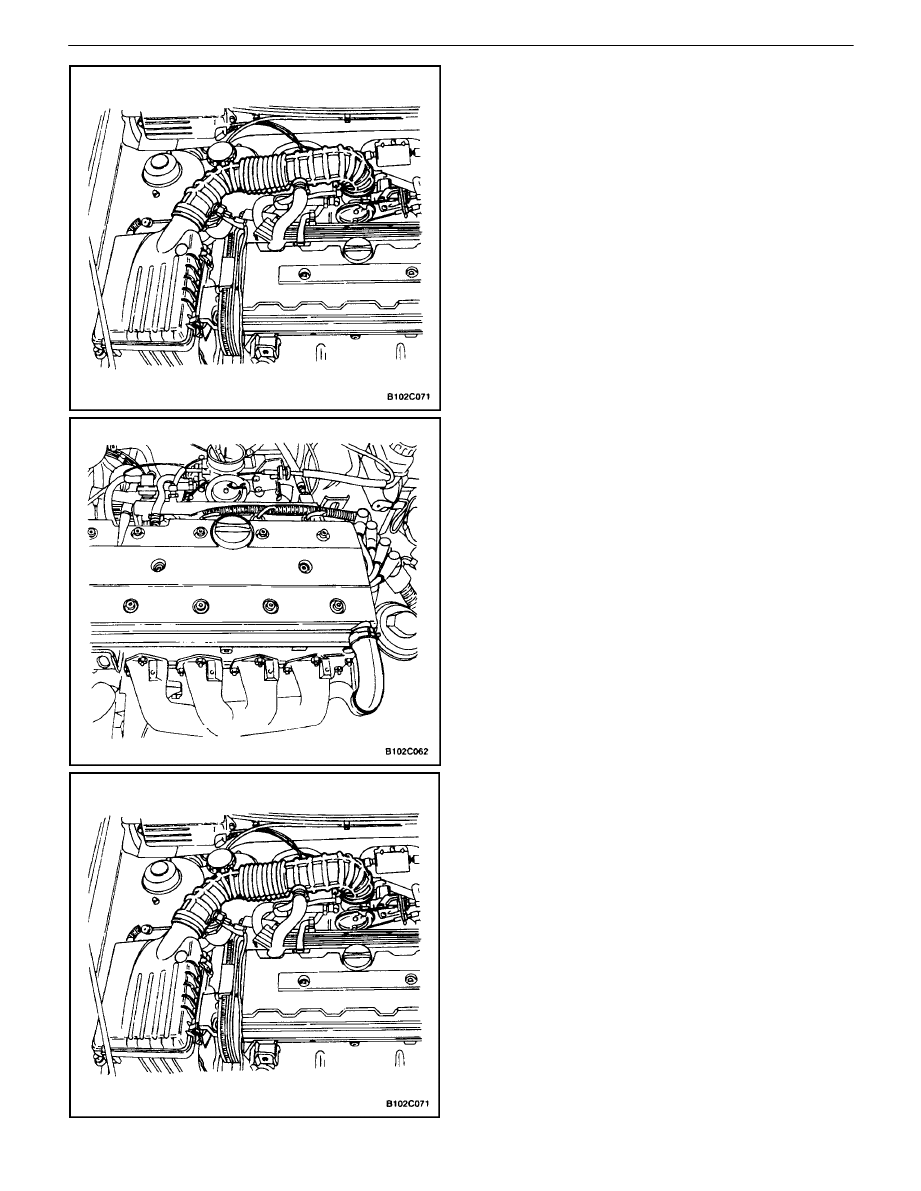
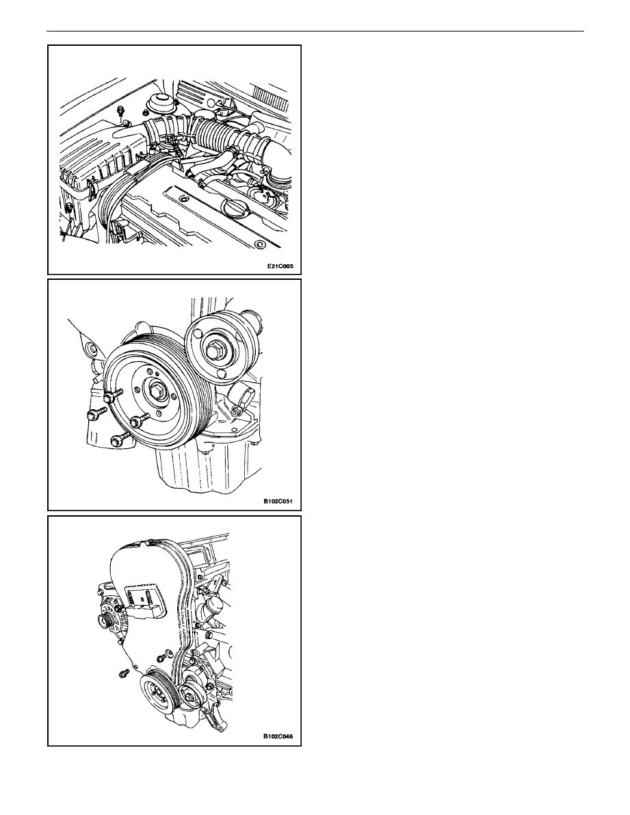
6. Disconnect the intake air temperature sensor con-
nector.
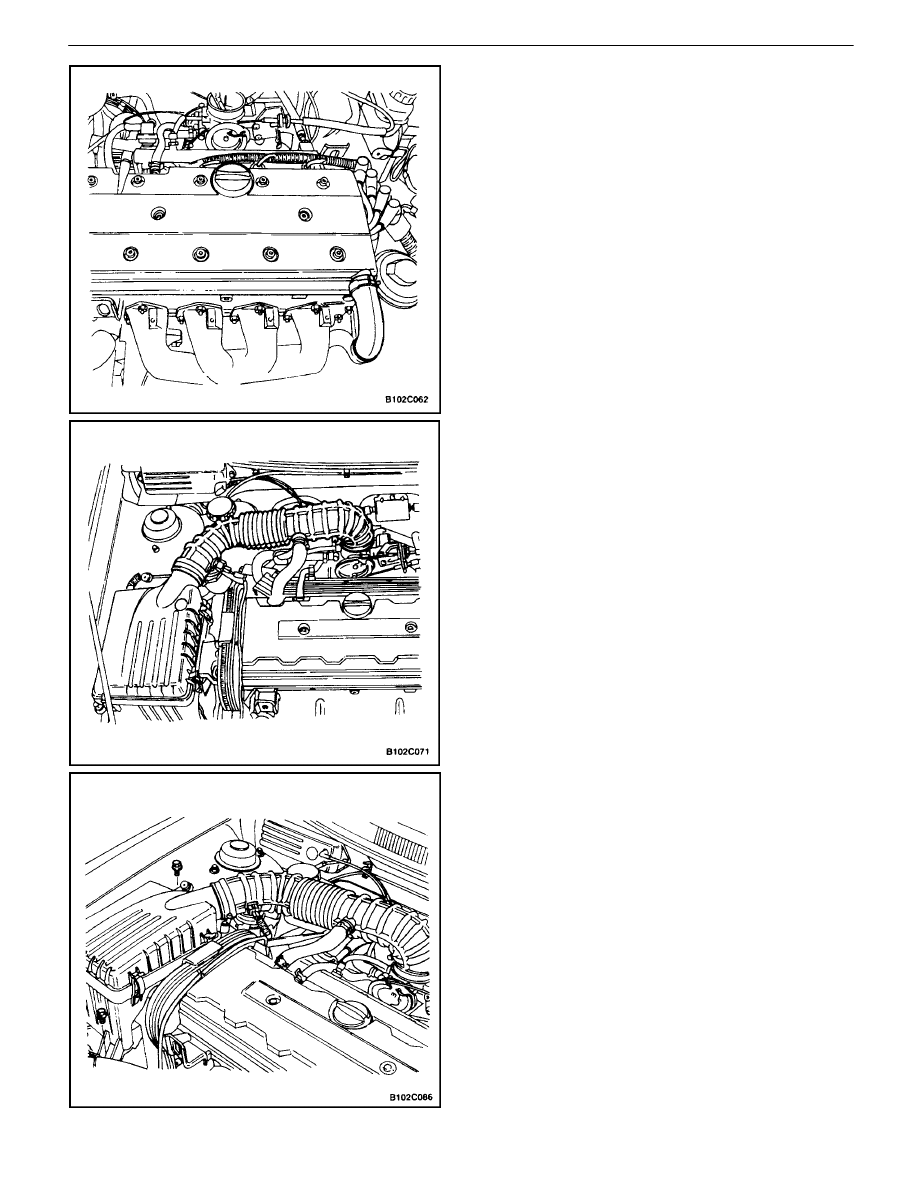
7. Disconnect the breather tube from the valve cover.
8. Disconnect the air intake tube from the throttle
body.
9. Disconnect the electronic ignition system (EI sys-
tem) ignition coil connector.
10. Disconnect the pre–converter oxygen sensor con-
nector.
11. Disconnect the idle air control valve connector.
12. Disconnect the throttle position sensor connector.
13. Disconnect the engine coolant temperature sensor
connector.
14. Disconnect the coolant temperature sensor connec-
tor.
15. Disconnect the camshaft position sensor.
DOHC ENGINE MECHANICAL 1C – 15
DAEWOO V–121 BL4
16. Remove the air filter housing bolts.
17. Remove the air filter housing.
18. Remove the right front wheel. Refer to Section 2E,
Tires and Wheels.
19. Remove the right front splash shield.
20. Install the engine assembly lift support J–28467–B.
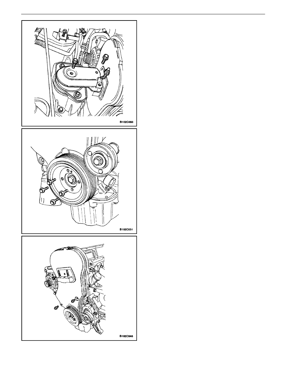
21. Remove the right engine mount bracket and bolts.
22. Disconnect the upper radiator hose at the thermo-
stat housing.
23. Remove the serpentine accessory drive belt. Refer
to Section 6B, Power Steering Pump.
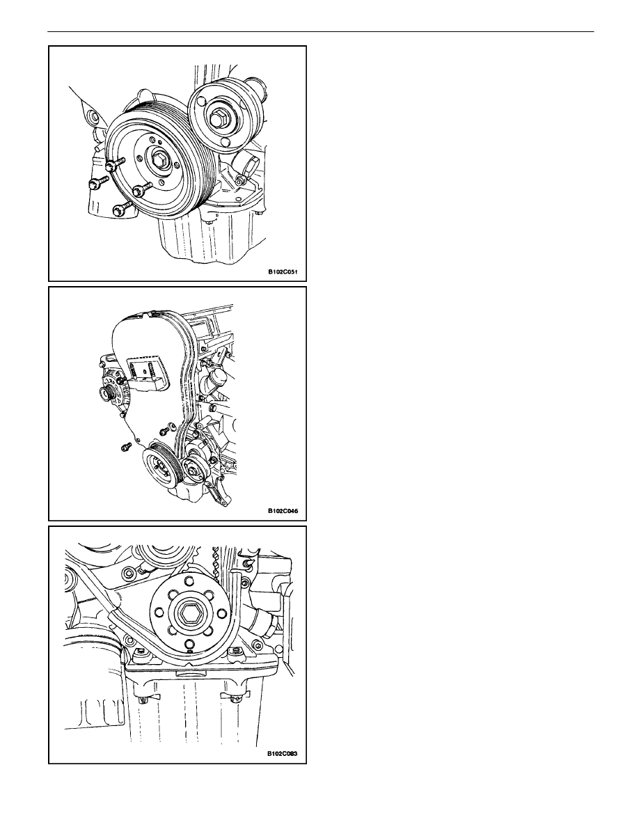
24. Remove the crankshaft pulley bolts.
25. Remove the crankshaft pulley.
26. Remove the front timing belt cover bolts.
27. Remove the front timing belt cover.
1C – 16
I
DOHC ENGINE MECHANICAL
DAEWOO V–121 BL4
28. Remove the timing belt. Refer to ”Timing Belt” in
this section.
29. Disconnect the breather tube at the valve cover.
30. Remove the spark plug cover bolts.
31. Remove the spark plug cover.
32. Disconnect the ignition wires from the spark plugs.
33. Remove the valve cover nuts.
34. Remove the valve cover washers.
35. Remove the valve cover and the valve cover gas-
ket.
Notice : Take extreme care to prevent any scratches,
nicks or damage to the camshafts.
36. While holding the intake camshaft firmly in place,
remove the intake camshaft gear bolt.
37. Remove the intake camshaft gear.
38. While holding the exhaust camshaft firmly in place,
remove the exhaust camshaft gear bolt.
39. Remove the exhaust camshaft gear.
40. Remove the timing belt automatic tensioner bolts.
41. Remove the timing belt automatic tensioner.
DOHC ENGINE MECHANICAL 1C – 17
DAEWOO V–121 BL4
42. Remove the timing belt idler pulley bolt and nut.
43. Remove the timing belt idler pulleys.
44. Remove the engine mount bolts.
45. Remove the engine mount.
46. Remove the rear timing belt cover bolts.
47. Remove the rear timing belt cover.
48. Remove the auxiliary catalytic converter nuts at the
exhaust manifold.
49. Disconnect all of the necessary vacuum hoses.
1C – 18
I
DOHC ENGINE MECHANICAL
DAEWOO V–121 BL4
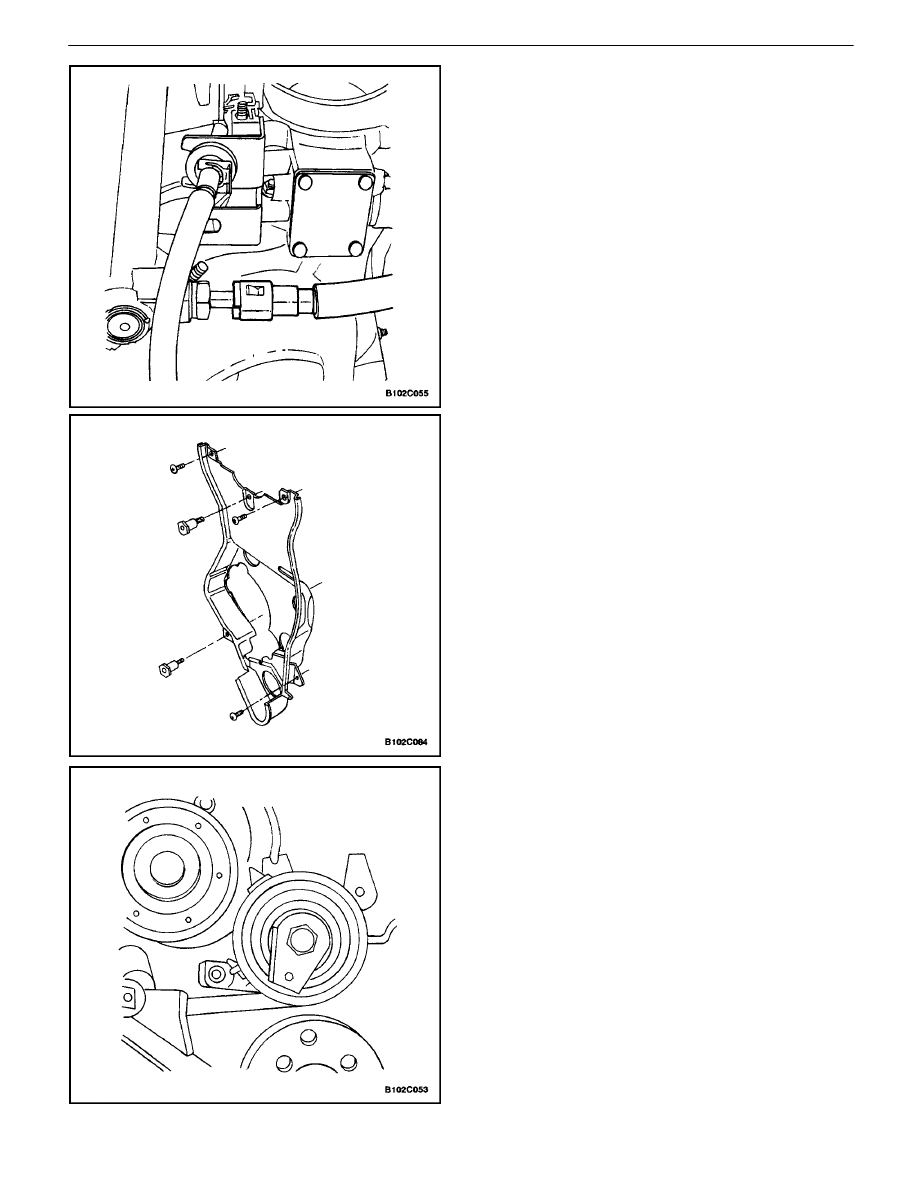
50. Disconnect the fuel return line at the fuel pressure
regulator.
51. Disconnect the fuel feed line at the fuel rail.
52. Remove the generator adjusting bracket retaining
bolt and the bracket.
53. Disconnect the coolant hose at the rear cylinder
head and ignition coil exhaust gas recirculation
(EGR) bracket.
54. Disconnect the surge tank coolant hose at the
throttle body.
55. Remove the fuel rail assembly. Refer toSection 1F,
Engine Controls.
56. Remove the generator–to–intake manifold support
bracket bolts at the cylinder head and the intake
manifold.
57. Remove the generator support bracket.
58. Remove the intake manifold–to–generator strap
bracket bolt and loosen the bolt on the generator.
59. Move the strap clear of the intake manifold.
60. Remove the evaporative emission canister purge
solenoid bracket bolt and move the bracket clear.
61. Disconnect the throttle cable at the throttle body
and the intake manifold.
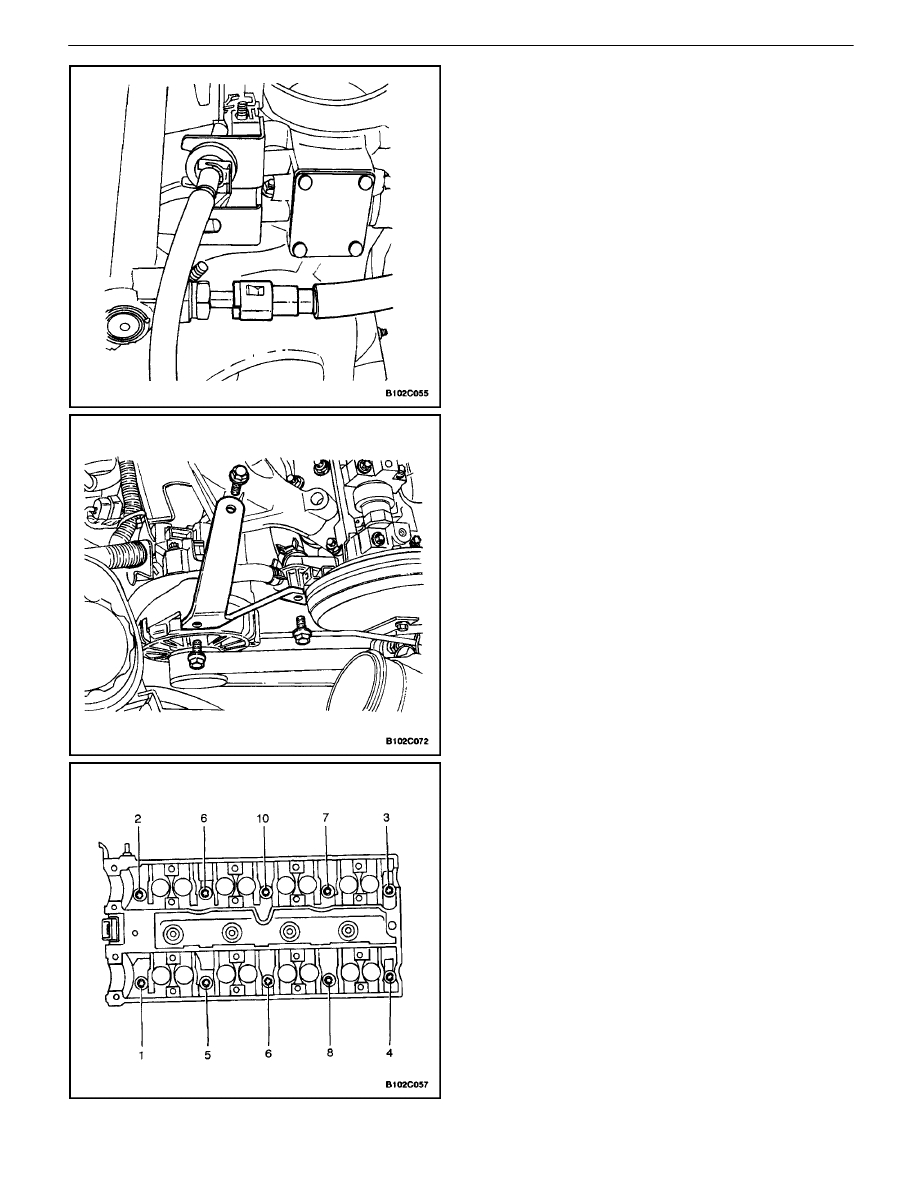
62. Loosen all of the cylinder head bolts gradually and
in the sequence shown.
63. Remove the cylinder head bolts.
64. Remove the cylinder head with the intake manifold
and the exhaust manifold attached.
Notice : Prevent any engine oil or coolant from entering
the cylinders when removing the cylinder head.
65. Remove the cylinder head gasket.
DOHC ENGINE MECHANICAL 1C – 19
DAEWOO V–121 BL4
Cleaning Procedure
1. Clean the gasket surfaces of the cylinder head and
the engine block.
2. Make sure the gasket surfaces of the cylinder head
and the engine block are free of nicks and heavy
scratches.
3. Clean the cylinder head bolts.
4. Inspect the cylinder head for warpage. Refer to
”Cylinder Head and Valve Train Components” in
this section.
Installation Procedure
1. Install the cylinder head gasket.
2. Install the cylinder head with the intake manifold
and the exhaust manifold attached.
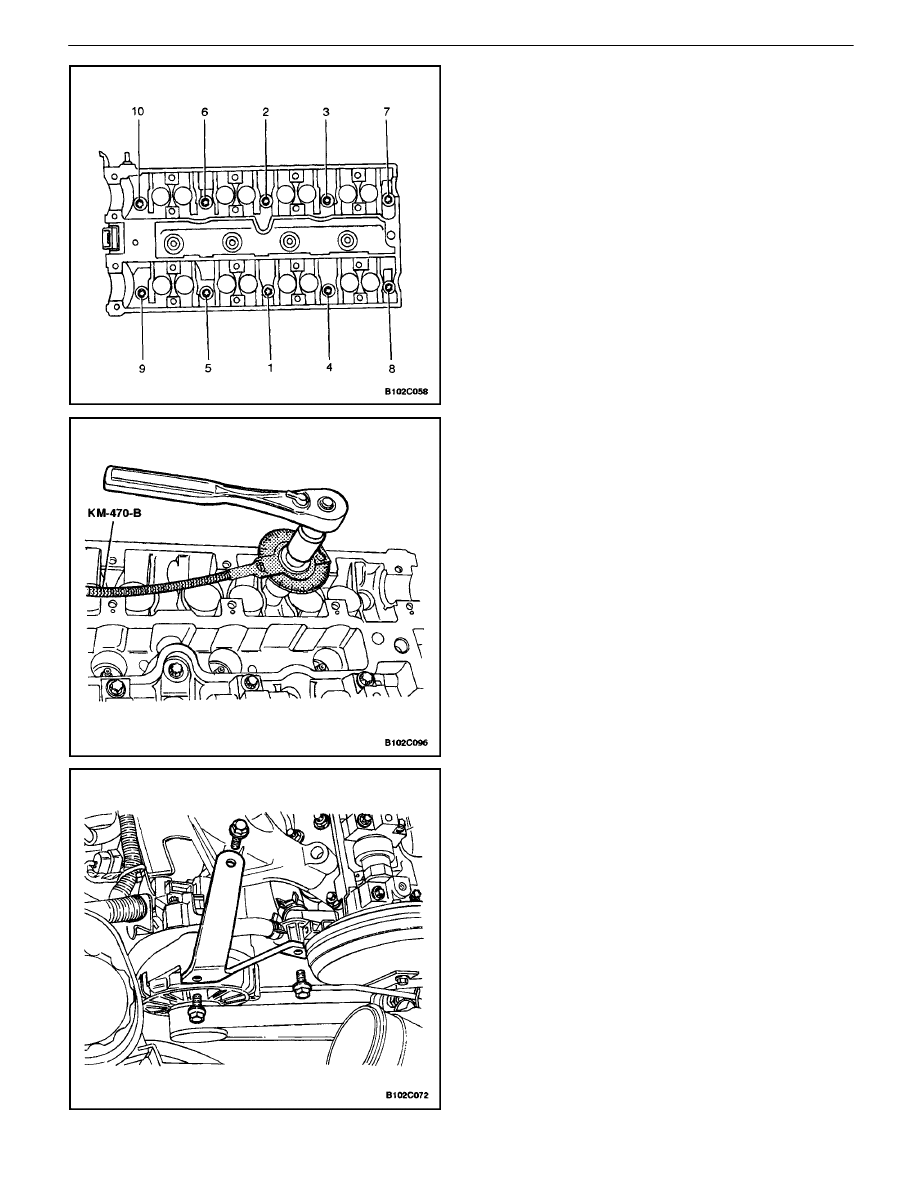
3. Install the cylinder head bolts.
4. Tighten the cylinder head bolts gradually and in the
sequence shown.
Tighten
Tighten the cylinder head bolts to 25 N
S
m (18 lb–ft)
and turn the bolts another 3 turns of 90 degrees using
the angular torque gauge KM–470–B.
5. Connect the throttle cable at the throttle body and
the intake manifold.
6. Install the generator–to–intake manifold support
bracket.
7. Install the intake generator–to–manifold support
bracket bolts.
Tighten
Tighten the generator–to–intake manifold support
bracket bolts to the intake manifold to 35 N
S
m (26 lb–
ft).
8. Install the intake manifold support bracket bolt to
the generator.
Tighten
Tighten the intakemanifold support bracket bolt at the
generator to 20 N
S
m (15 lb–ft).
9. Connect the surge tank coolant hose at the throttle
body.
10. Connect the coolant hose to the rear cylinder head
and ignition coil EGR bracket.
1C – 20
I
DOHC ENGINE MECHANICAL
DAEWOO V–121 BL4
11. Connect the fuel feed line at the fuel rail.
12. Connect the fuel return line at the fuel rail.
13. Connect all of the necessary vacuum hoses.
14. Install the fuel rail assembly. Refer to Section 1F,
Engine Controls (DOHC).
15. Install the auxiliary catalytic converter nuts at the
exhaust manifold flange.
Tighten
Tighten the auxiliary catalytic converter–to–exhaust
manifold nuts to 40 N
S
m (30 lb–ft).
16. Install the rear timing belt cover.
17. Install the rear timing belt cover bolts.
Tighten
Tighten the rear timing belt cover bolts to 6 N
S
m (53
lb–in).
18. Install the engine mount and retaining bolts.
Tighten
Tighten the engine mount retaining bolts to 60 N·m
(44 lb–ft).
19. Install the timing belt automatic tensioner.
20. Install the timing belt automatic tensioner bolt.
Tighten
Tighten the timing belt automatic tensioner bolts to 25
N
S
m (18 lb–ft).
21. Install the timing belt idler pulleys.
22. Install the timing belt idler pulley nuts.
Tighten
Tighten the timing belt idler pulley bolt to 25 N
S
m (18
lb–ft).
Tighten
Tighten the timing belt idler pulley nut to 25 N
S
m (18
lb–ft).
DOHC ENGINE MECHANICAL 1C – 21
DAEWOO V–121 BL4
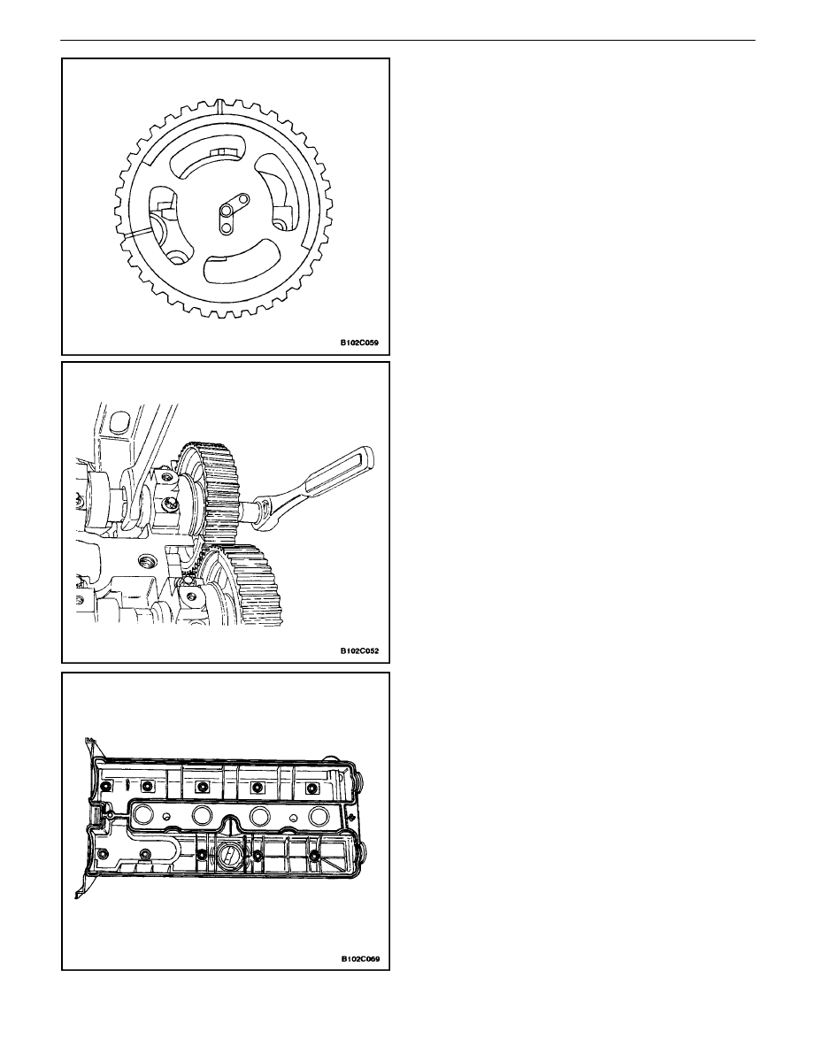
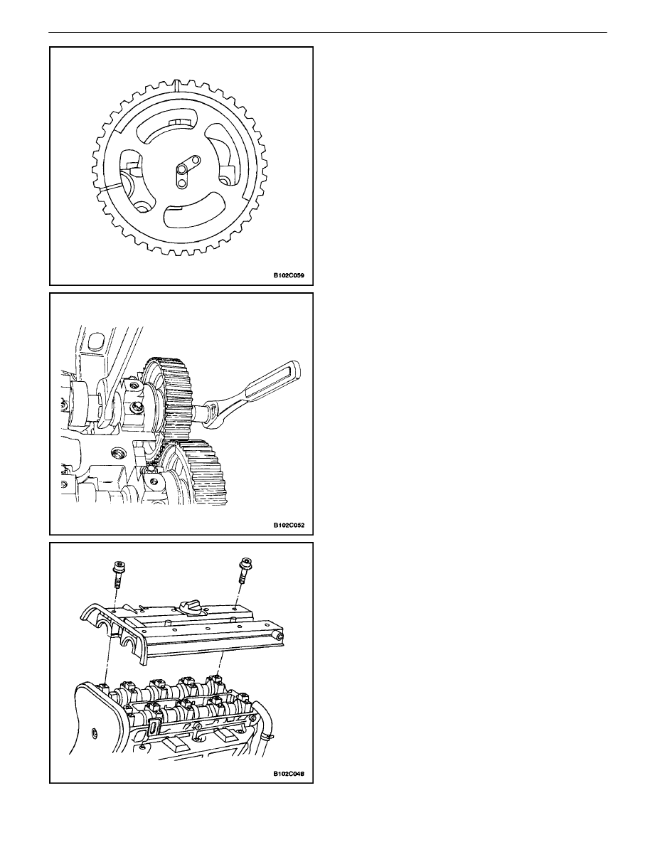
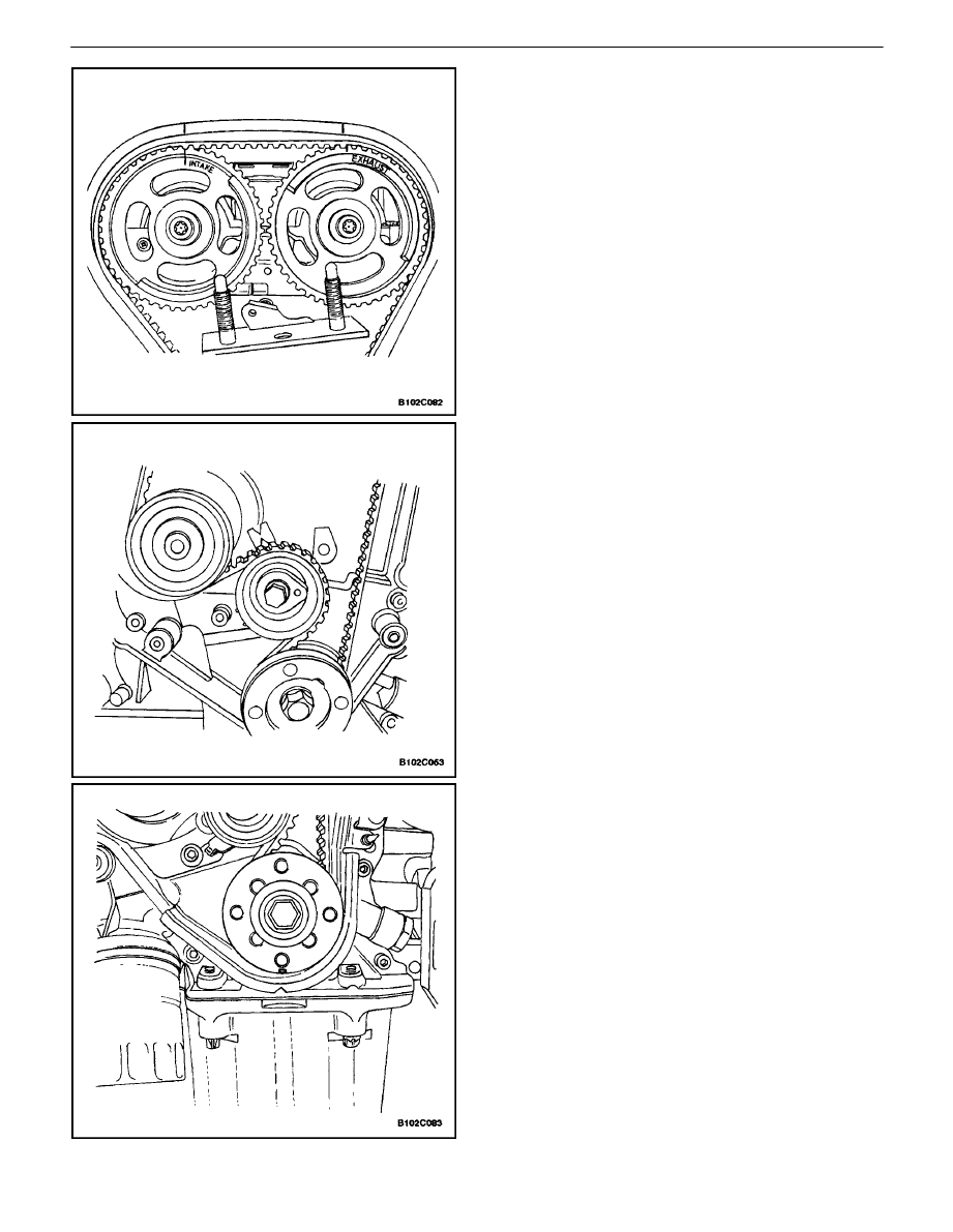
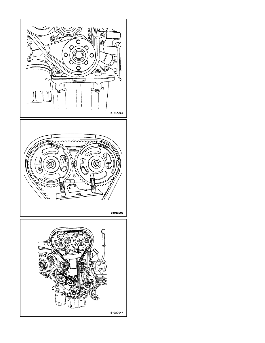
23. Install the camshaft gears with the timing marks at
the front.
24. Insert the guide pin of the intake camshaft into the
”IN” bore.
25. Insert the guide pin of the exhaust camshaft into
the ”EX” bore.
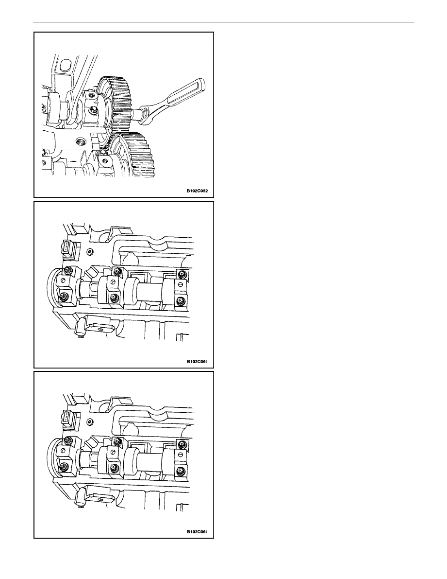
26. Install the camshaft gears by counterholding on the
hex of the camshaft with an open–ended wrench.
27. Install the camshaft gear with a new bolt to the
camshaft.
Tighten
Tighten the intake camshaft gear bolt to 50 N
S
m (37
lb–ft). Using the angular torque gauge KM–470–B,
tighten the bolt another 60 degrees plus 15 degrees.
28. While holding the exhaust camshaft firmly in place,
install the exhaust camshaft gear bolt.
Tighten
Tighten the exhaust camshaft gear bolt to 50 N
S
m (37
lb–ft). Using the angular torque gauge KM–470–B,
tighten the bolt another 60 degrees plus 15 degrees.
29. Apply a small amount of gasket sealant to the cor-
ners of the front camshaft caps and to the top of
the rear valve cover–to–cylinder head seal.
30. Install the valve cover and the valve cover gasket.
31. Install the valve cover washers.
32. Install the valve cover bolts.
Tighten
Tighten the valve cover bolts to 8 N·m (71 lb–in).
1C – 22
I
DOHC ENGINE MECHANICAL
DAEWOO V–121 BL4
33. Connect the ignition wires to the spark plugs.
34. Install the spark plug cover.
35. Install the spark plug cover bolts.
Tighten
Tighten the spark plug cover bolts to 8 N
S
m (71 lb–in).
36. Connect the breather tube to the valve cover.
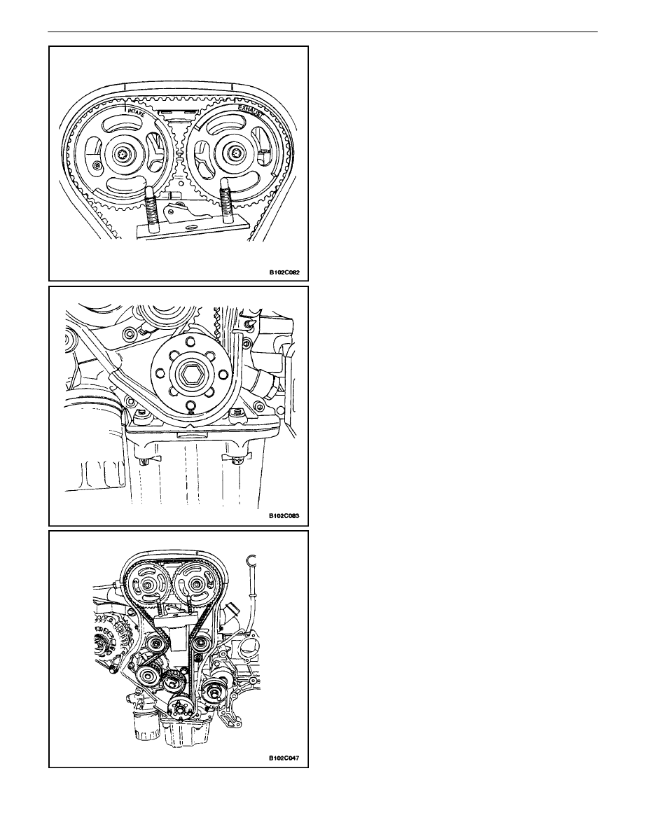
37. Align the timing marks on the camshaft gears to the
notches on the valve cover, using the intake gear
mark for the intake gear and the exhaust gear mark
for the exhaust gear.
38. Align the mark on the crankshaft gear with the
notch at the bottom of the rear timing belt cover.
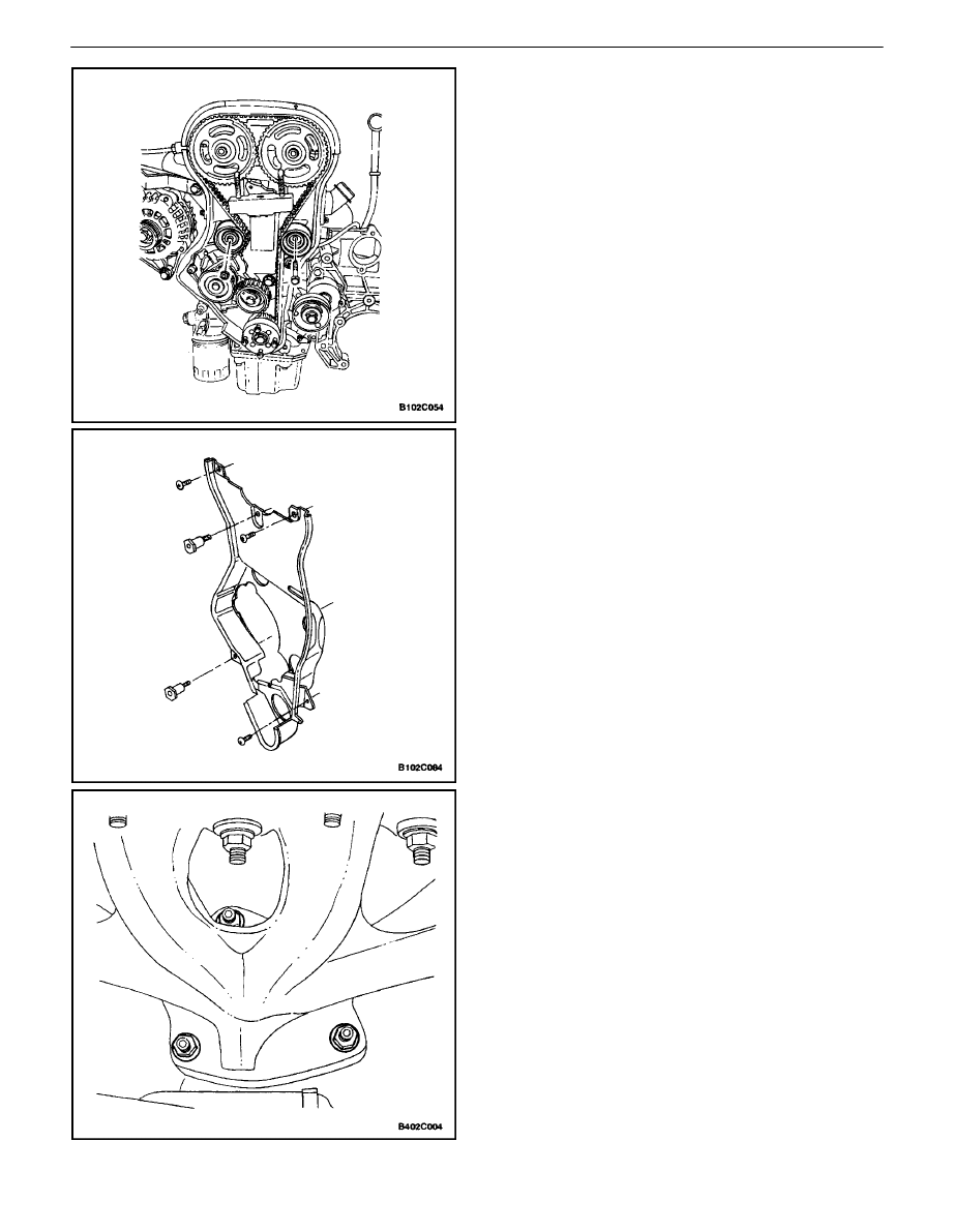
39. Install the timing belt.
40. Check and adjust the timing belt tension. Refer to
”Timing Belt Check and Adjust” in this section.
DOHC ENGINE MECHANICAL 1C – 23
DAEWOO V–121 BL4
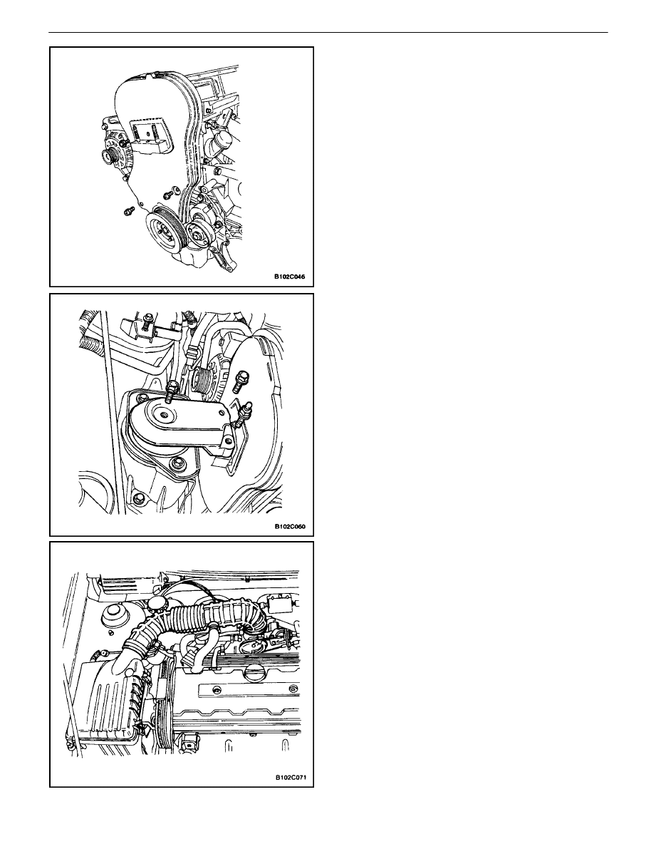
41. Install the front timing belt cover.
42. Install the front timing belt cover bolts.
Tighten
Tighten the upper and lower front timing belt cover
bolts to 6 N
S
m (53 lb–in).
43. Install the crankshaft pulley.
44. Install the crankshaft pulley bolts.
Tighten
Tighten the crankshaft pulley bolts to 20 N
S
m (15 lb–
ft).
45. Install the right engine mount bracket and retaining
bolts.
Tighten
Tighten the right engine mount bracket retaining bolts
to 60 N
S
m (44 lb–ft).
46. Remove the engine assembly lift support
J–28467–B.
47. Install the serpentine accessory drive belt. Refer to
Section 6B, Power Steering Pump.
48. Connect the upper radiator hose to the thermostat
housing.
49. Install the right front splash shield.
50. Install the right front wheel. Refer to Section 2E,
Tires and Wheels.
51. Install the air filter housing.
52. Install the air filter housing bolts.
Tighten
Tighten the air filter housing bolts to 8 N
S
m (71 lb–in).
53. Connect the air intake tube to the throttle body.
54. Connect the breather tube to the valve cover.
55. Connect the intake air temperature sensor connec-
tor.
56. Connect the camshaft position sensor.
1C – 24
I
DOHC ENGINE MECHANICAL
DAEWOO V–121 BL4
57. Connect the coolant temperature sensor connector.
58. Connect the engine coolant temperature sensor
connector.
59. Connect the idle air control valve connector.
60. Connect the throttle position sensor connector.
61. Install the evaporative emission canister purge so-
lenoid bracket bolt.
Tighten
Tighten the evaporative emission canister purge sole-
noid bracket bolt to 5 N
S
m (44 lb–in).
62. Connect the EI system ignition coil connector.
63. Connect the pre–converter oxygen sensor connec-
tor.
64. Connect the PCM/ECM ground terminal.
65. Install the fuel pump fuse.
66. Connect the negative battery ground cable.
67. Refill the engine cooling system. Refer to Section
1D, Engine Cooling.
CAMSHAFTS
Removal Procedure
1. Remove the timing belt. Refer to ”Timing Belt” in
this section.
2. Disconnect the breather tube at the valve cover.
3. Disconnect the crankcase ventilation tube at the
valve cover.
4. Remove the spark plug cover bolts.
5. Remove the spark plug cover.
6. Disconnect the ignition wires from the spark plugs.
7. Disconnect the camshaft position sensor.
8. Remove the valve cover bolts.
9. Remove the valve cover washers.
10. Remove the valve cover and the valve cover gas-
ket.
DOHC ENGINE MECHANICAL 1C – 25
DAEWOO V–121 BL4
Notice : Take extreme care to prevent any scratches,
nicks or damage to the camshafts.
11. While holding the intake camshaft firmly in place,
remove the intake camshaft gear bolt.
12. Remove the intake camshaft gear.
13. While holding the exhaust camshaft firmly in place,
remove the exhaust camshaft gear bolt.
14. Remove the exhaust camshaft gear.
15. Loosen the camshaft bearing cap bolts in stages of
one–half to one turn.
16. Remove the camshaft bearing cap bolts from the
cylinder head.
17. Remove the camshafts.
18. Remove the seal ring from the camshafts.
Important : The camshaft must detach evenly from the
bearing seats in the front guide bearing.
19. Check the camshaft and bearing seats for wear and
replace them if necessary.
Installation Procedure
Notice : Take extreme care to prevent any scratches,
nicks or damage to the camshafts.
1. Lubricate the camshaft journals and the camshaft
caps with engine oil.
2. Install the intake camshaft.
3. Install the intake camshaft bearing caps in their
original positions.
4. Install the intake camshaft bearing cap bolts.
5. Install the exhaust camshaft.
6. Install the exhaust camshaft bearing caps in their
original positions.
7. Install the exhaust camshaft bearing cap bolts.
8. Tighten the camshaft cap bolts gradually and in the
sequence shown for each camshaft bearing cap.
Tighten
Tighten the camshaft cap bolts to 8 N
S
m (71 lb–in).
1C – 26
I
DOHC ENGINE MECHANICAL
DAEWOO V–121 BL4
9. Measure the intake camshaft end play and the ex-
haust camshaft end play. Refer to ”Engine Specifi-
cations” in this section.
10. Install the intake camshaft gear.
11. While holding the intake camshaft firmly in place,
install the intake camshaft gear bolt.
Tighten
Tighten the intake camshaft gear bolt to 50 N
S
m (37
lb–ft). Using the angular torque gauge KM–470–B,
tighten the bolt another 60 degrees plus 15 degrees.
12. Install the exhaust camshaft gear.
13. While holding the exhaust camshaft firmly in place,
install the exhaust camshaft gear bolt.
Tighten
Tighten the exhaust camshaft gear bolt to 50 N
S
m (37
lb–ft). Using the angular torque gauge KM–470–B,
tighten the bolt another 60 degrees plus 15 degrees.
14. Install the valve cover and the valve cover gasket.
15. Install the valve cover washers.
16. Install the valve cover bolts.
Tighten
Tighten the valve cover bolts to 8 N
S
m (71 lb–in).
17. Connect the camshaft position sensor.
DOHC ENGINE MECHANICAL 1C – 27
DAEWOO V–121 BL4
18. Connect the ignition wires to the spark plugs.
19. Install the spark plug cover.
20. Install the spark plug cover bolts.
Tighten
Tighten the spark plug cover bolts to 3 N
S
m (27 lb–in).
21. Connect the breather tube to the valve cover.
22. Connect the crankcase ventilation tube to the valve
cover.
23. Install the timing belt. Refer to ”Timing Belt” in this
section.
TIMING BELT CHECK AND ADJUST
Adjustment Procedure
1. Disconnect the negative battery cable.
2. Disconnect the intake air temperature sensor con-
nector.
3. Remove the air intake tube from the throttle body.
4. Remove the breather tube from the valve cover.
5. Remove the air filter housing bolts.
6. Remove the air filter housing.
7. Remove the right front wheel. Refer to Section 2E,
Tires and Wheels.
8. Remove the right front splash shield.
1C – 28
I
DOHC ENGINE MECHANICAL
DAEWOO V–121 BL4
9. Remove the serpentine accessory drive belt. Refer
toSection 6B, Power Steering Pump.
10. Remove the crankshaft pulley bolts.
11. Remove the crankshaft pulley.
12. Remove the right engine mount bracket. Refer to
”Engine Mount”in this section.
13. Remove the front timing belt cover bolts.
14. Remove the front timing belt cover.
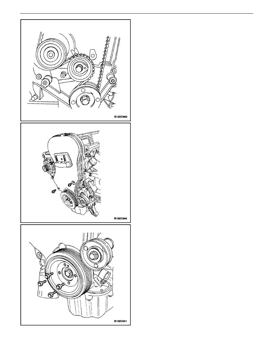
15. Rotate the crankshaft at least one full turn clock-
wise using the crankshaft gear bolt.
16. Align the mark on the crankshaft gear with the
notch at the bottom of the rear timing belt cover.
DOHC ENGINE MECHANICAL 1C – 29
DAEWOO V–121 BL4
17. Align the camshaft gear timing marks. Use the ex-
haust gear mark for the exhaust gear and the in-
take gear mark for the intake gear, since the gears
are interchangeable
18. Loosen the automatic tensioner bolt. To relieve the
belt tension, turn the hex–key tab counterclockwise.
19. Rotate the automatic tensioner hex–key tab clock-
wise until the adjust arm pointer of the timing belt
automatic tensioner is aligned with the notch in the
timing belt automatic tensioner bracket.
20. Tighten the automatic tensioner bolt.
21. Rotate the crankshaft two full turns clockwise using
the crankshaft gear bolt.
22. Check the automatic tensioner pointer.

1C – 30
I
DOHC ENGINE MECHANICAL
DAEWOO V–121 BL4
23. When the adjust arm pointer of the timing belt auto-
matic tensioner is aligned with the notch on the tim-
ing belt automatic tensioner bracket, the belt is ten-
sioned correctly.
Tighten
Tighten the automatic tensioner bolt to 25 N
S
m (18 lb–
ft).
24. Install the front timing belt cover.
25. Install the front timing belt cover bolts.
Tighten
Tighten the front timing belt cover bolts to 6 N
S
m (53
lb–in).
26. Install the crankshaft pulley.
27. Install the crankshaft pulley bolts.
Tighten
Tighten the crankshaft pulley bolt to 20 N
S
m (15 lb–ft).
28. Install the right engine mount bracket. Refer to”En-
gine Mount”in this section.
29. Install the serpentine accessory drive belt. Refer to
Section 6B, Power Steering Pump.
DOHC ENGINE MECHANICAL 1C – 31
DAEWOO V–121 BL4
30. Install the right front splash shield.
31. Install the right front wheel. Refer to Section 2E,
Tires and Wheels.
32. Install the air filter housing.
33. Install the air filter housing bolts.
Tighten
Tighten the air filter housing bolts to 8 N
S
m (71 lb–in).
34. Connect the air intake tube to the throttle body.
35. Connect the breather tube to the valve cover.
36. Connect the intake air temperature sensor connec-
tor.
37. Connect the negative battery cable.
TIMING BELT
Removal Procedure
1. Disconnect the negative battery cable.
2. Disconnect the intake air temperature sensor con-
nector.
3. Disconnect the air intake tube from the throttle
body.
4. Disconnect the breather tube from the valve cover.
1C – 32
I
DOHC ENGINE MECHANICAL
DAEWOO V–121 BL4
5. Remove the air filter housing bolts.
6. Remove the air filter housing.
7. Remove the right front wheel. Refer to Section 2E,
Tires and Wheels.
8. Remove the right front splash shield.
9. Remove the serpentine accessory drive belt. Refer
toSection 6B, Power Steering Pump.
10. Remove the crankshaft pulley bolts.
11. Remove the crankshaft pulley.
12. Remove the right engine mount bracket. Refer to
”Engine Mount” in this section.
13. Remove the front timing belt cover bolts.
14. Remove the front timing belt cover.
DOHC ENGINE MECHANICAL 1C – 33
DAEWOO V–121 BL4
15. Using the crankshaft gear bolt, rotate the crank-
shaft clockwise until the timing mark on the crank-
shaft gear is aligned with the notch at the bottom of
the rear timing belt cover.
Notice : The camshaft gears must align with the notch on
the valve cover or damage to the engine could result.
16. Align the camshaft gears with the notch on the
valve cover.
Important : Use the intake gear mark for the intake cam-
shaft gear and the exhaust gear mark for the exhaust cam-
shaft gear since both gears are interchangeable.
17. Remove the timing belt.
18. Loosen the automatic tensioner bolt. Turn the
hexkey tab to relieve belt tension.

1C – 34
I
DOHC ENGINE MECHANICAL
DAEWOO V–121 BL4
Installation Procedure
1. Align the timing mark on the crankshaft gear with
the notch on the bottom of the rear timing belt cov-
er.
2. Align the timing marks on the camshaft gears, us-
ing the intake gear mark for the intake gear and the
exhaust gear mark for the exhaust gear.
3. Install the timing belt.
DOHC ENGINE MECHANICAL 1C – 35
DAEWOO V–121 BL4
4. Turn the hex–key tab in a clockwise direction to
tension the belt. Turn until the pointer aligns with
the notch.
5. Install the automatic tensioner bolt.
Tighten
Tighten the automatic tensioner bolt to 25 N
S
m (18 lb–
ft).
6. Rotate the crankshaft two full turns clockwise using
the crankshaft pulley bolt.
7. Recheck the automatic tensioner pointer.
8. Install the front timing belt cover.
9. Install the front timing belt cover bolts.
Tighten
Tighten the front timing belt cover bolts to 6 N
S
m (53
lbin).
10. Install the right engine mount bracket. Refer to ”En-
gine Mounts” in this section.
11. Install the crankshaft pulley.
12. Install the crankshaft pulley bolts.
Tighten
Tighten the crankshaft pulley bolts to 20 N
S
m (15 lb–
ft).
1C – 36
I
DOHC ENGINE MECHANICAL
DAEWOO V–121 BL4
13. Install the serpentine accessory drive belt. Refer to
Section 2E, Tires and Wheels.
14. Install the right front splash shield.
15. Install the right front wheel. Refer to Section 6B,
Power Steering Pump.
16. Install the air filter housing.
17. Install the air filter housing bolts.
Tighten
Tighten the air filter housing bolts to 8 N
S
m (71 lb–in).
18. Connect the air intake tube to the throttle body.
19. Connect the breather tube to the valve cover.
20. Connect the intake air temperature sensor connec-
tor.
21. Connect the negative battery cable.
OIL PAN
Removal Procedure
1. Disconnect the negative battery cable.
2. Drain the engine oil from the engine crankcase.
3. Disconnect the post–converter heated oxygen sen-
sor.
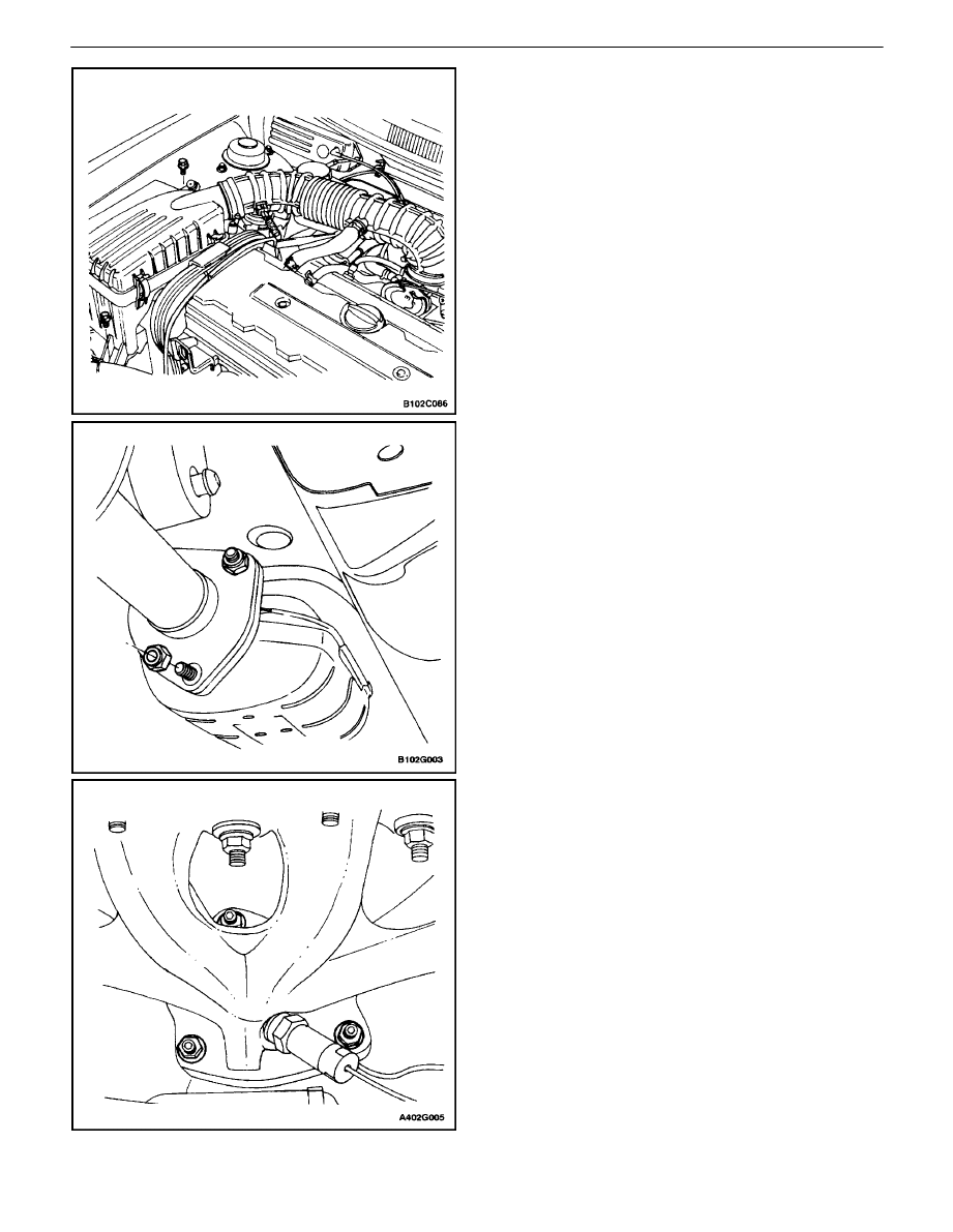
4. Remove the auxiliary catalytic converter upper
flange nuts from the exhaust manifold and the sup-
port bracket bolts.
5. Remove the front muffler pipe retaining nuts from
the main catalytic converter.
6. Remove both catalytic converters as a unit.
DOHC ENGINE MECHANICAL 1C – 37
DAEWOO V–121 BL4
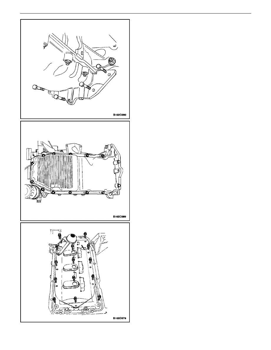
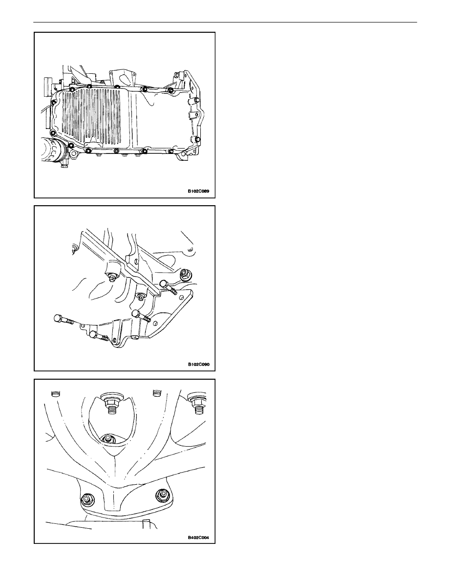
7. Remove the oil pan flange–to–transaxle retaining
bolts.
8. Remove the oil pan retaining bolts.
9. Remove the oil pan from the engine block.
Cleaning Procedure
1. Clean the oil pan sealing surface.
2. Clean the engine block sealing surface.
3. Clean the oil pan retaining bolts.
4. Clean the oil pan attaching bolt holes in the engine
block.
5. Clean the oil pan splash shield.
1C – 38
I
DOHC ENGINE MECHANICAL
DAEWOO V–121 BL4
Installation Procedure
1. Coat the new oil pan gasket with sealant.
Important : Install the oil pan within 5 minutes after apply-
ing the liquid gasket to the oil pan.
2. Install the oil pan to the engine block.
3. Install the oil pan retaining bolts.
Tighten
Tighten the oil pan retaining bolts to 10 N
S
m (89 lb–in).
4. Install the oil pan flange–to–transaxle retaining
bolts.
Tighten
Tighten the oil pan flange–to–transaxle bolts to 40
N
S
m (30 lb–ft).
5. Install the catalytic converters.
Tighten
Tighten the auxiliary catalytic converter–to–exhaust
manifold nuts to 40 N
S
m (30 lb–ft).
DOHC ENGINE MECHANICAL 1C – 39
DAEWOO V–121 BL4
Tighten
Tighten the exhaust pipe support bracket bolts to 40
N
S
m (30 lb–ft).
Tighten
Tighten the front muffler pipe–to–main catalytic con-
verter nuts to 30 N
S
m (22 lb–ft).
6. Connect the post–converter oxygen sensor.
7. Connect the negative battery cable.
8. Refill the engine crankcase with engine oil.
OIL PUMP
Tools Required
KM–498–B Pressure Gauge
KM–135 Adapter
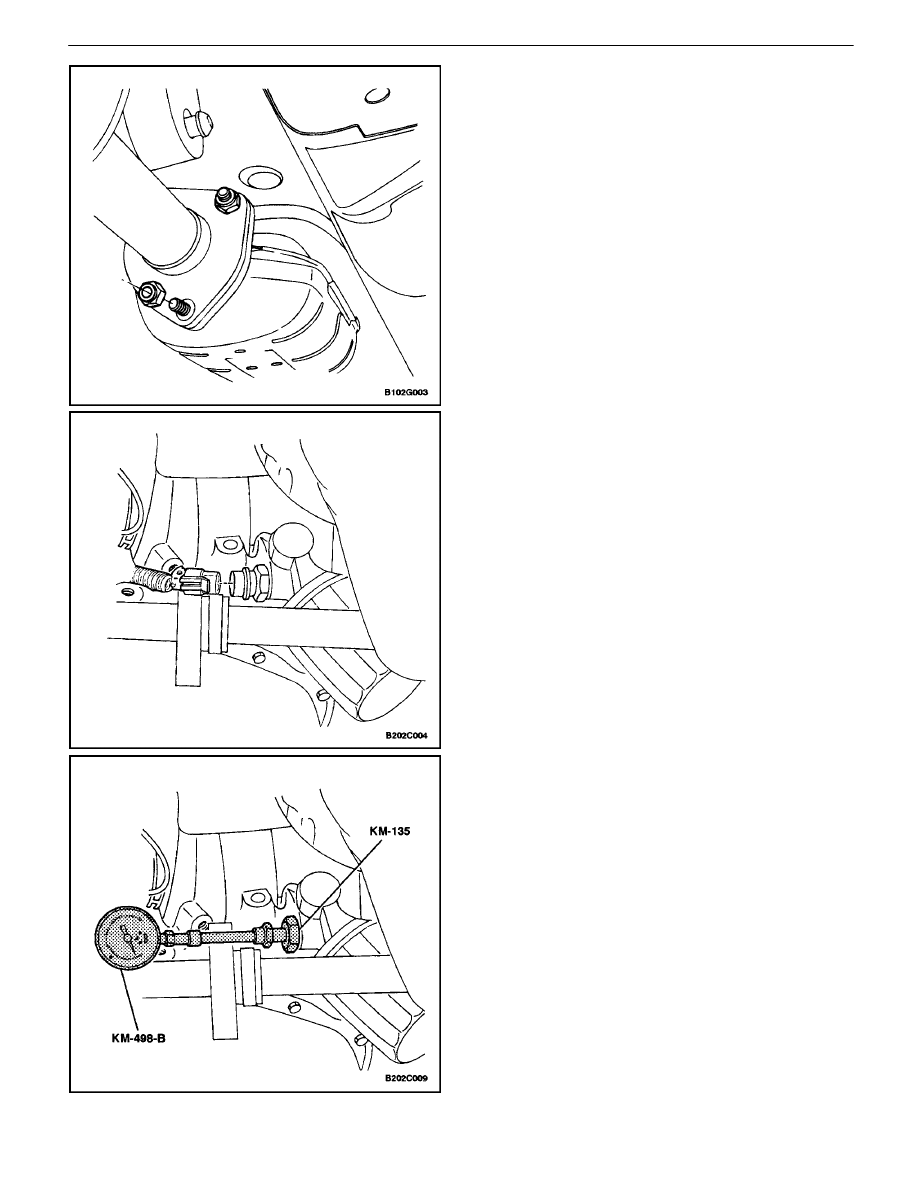
Engine Oil Pressure Inspection Procedure
1. Remove the right front wheel well splash shield.
2. Disconnect the oil pressure switch connector.
3. Install the adapter KM–135 in place of the oil pres-
sure switch.
4. Connect the pressure gauge KM–498–B to the
adapter.
5. Start the engine and check the oil pressure at idle
speed and engine temperature of 80
³
C (176
³
F).
The minimum oil pressure should be 30 kPa (4.35
psi).
6. Stop the engine and remove the pressure gauge
KM–498–B and the adapter KM–135.
1C – 40
I
DOHC ENGINE MECHANICAL
DAEWOO V–121 BL4
7. Install the oil pressure switch.
Tighten
Tighten the oil pressure switch to 40 N
S
m (30 lb–ft).
8. Connect the oil pressure switch connector.
9. Install the right front wheel well splash shield.
10. Check the oil level. Add oil until it reaches the full
mark.
Removal Procedure
1. Disconnect the negative battery cable.
2. Remove the rear timing belt cover. Refer to ”Rear
Timing Belt Cover” in this section.
3. Disconnect the oil pressure switch connector.
4. Remove the oil pan. Refer to ”Oil Pan” in this sec-
tion.
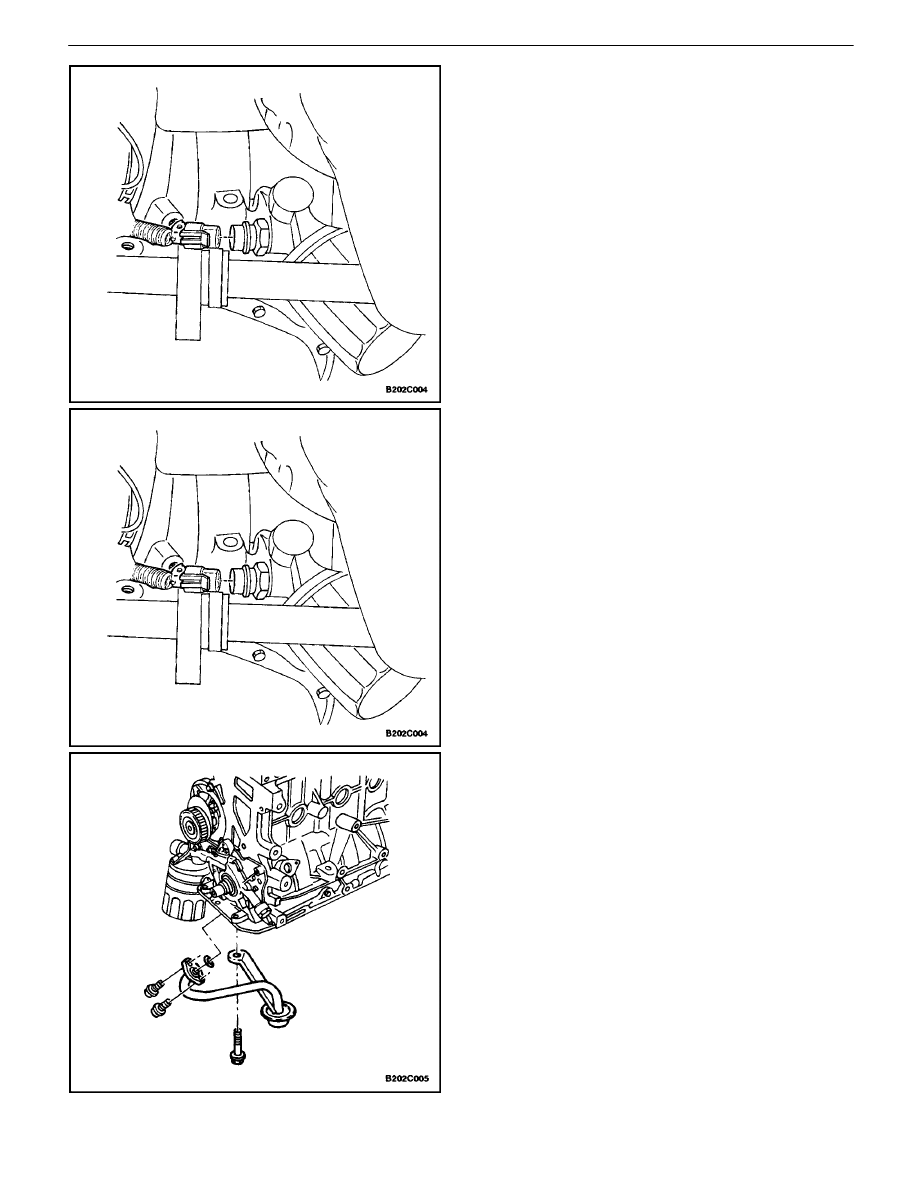
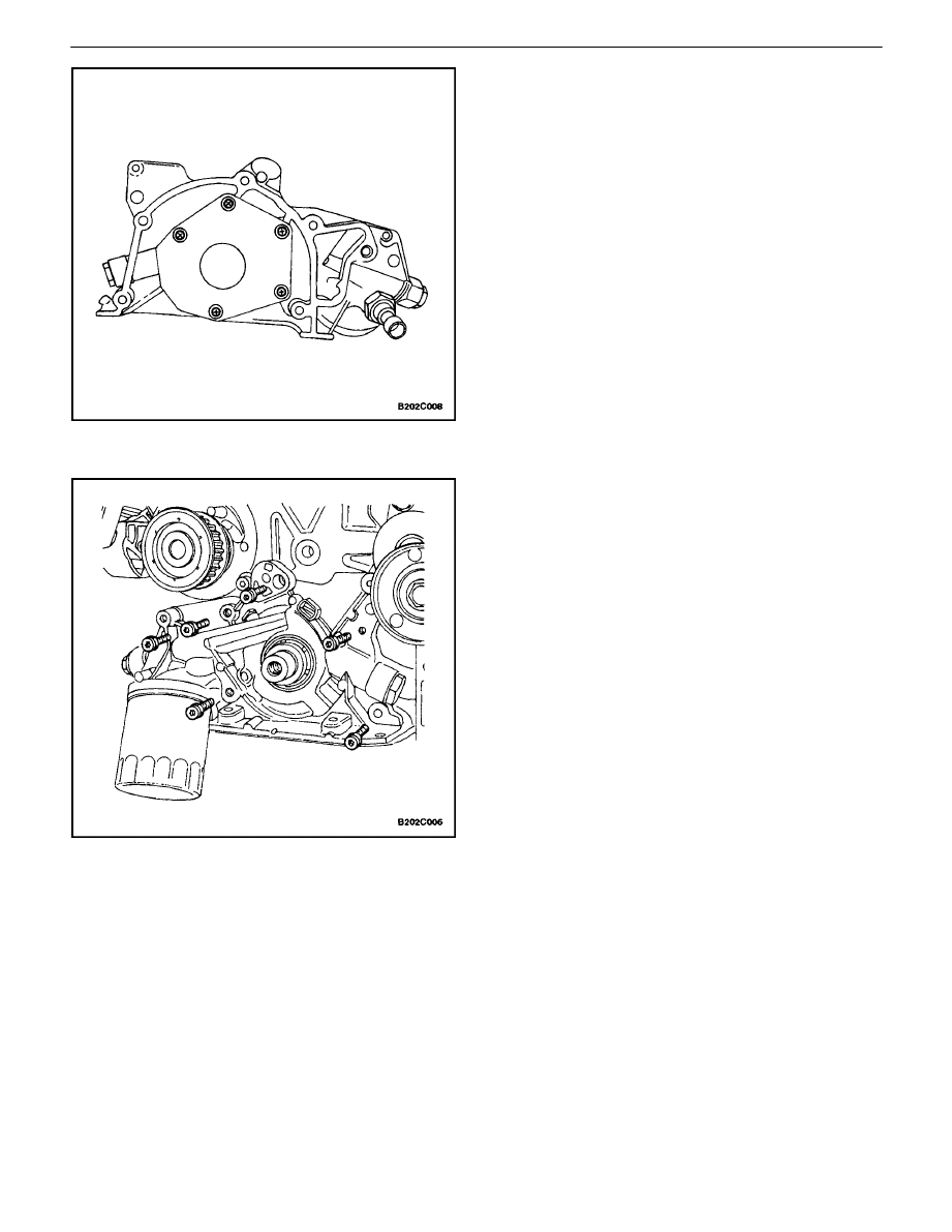
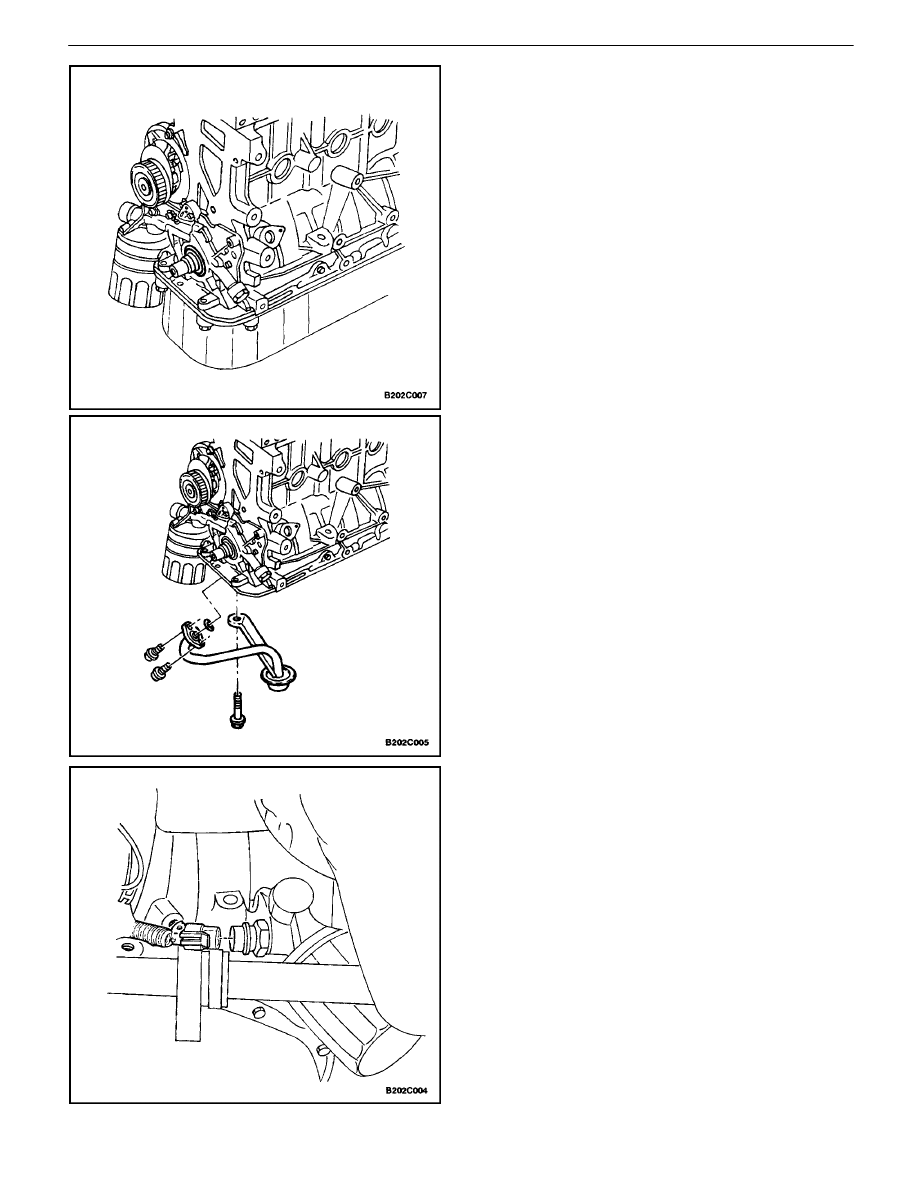
5. Remove the oil pump/pickup tube and support
bracket bolts.
6. Remove the oil pump/pickup tube.
DOHC ENGINE MECHANICAL 1C – 41
DAEWOO V–121 BL4
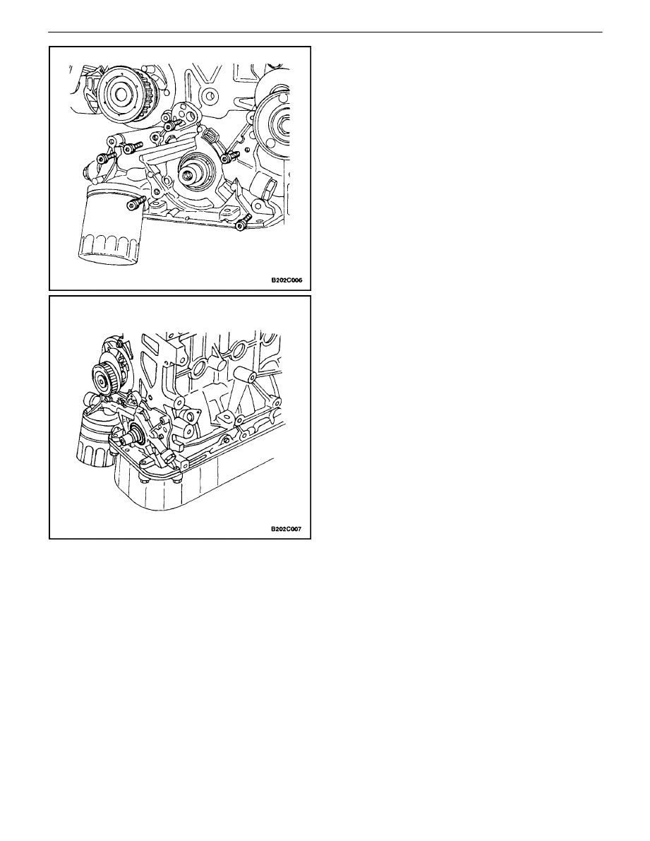
7. Remove the oil pump retaining bolts.
8. Carefully separate the oil pump and gasket from
the engine block and oil pan.
9. Remove the oil pump.
Inspection Procedure
1. Clean the oil pump and the engine block gasket
mating surface areas.
2. Remove the safety relief valve bolt.
3. Remove the safety relief valve and the spring.
4. Remove the oil pump–to–crankshaft seal.
1C – 42
I
DOHC ENGINE MECHANICAL
DAEWOO V–121 BL4
5. Remove the oil pump rear cover bolts.
6. Remove the rear cover.
7. Clean the oil pump housing and all the oil pump
parts.
8. Inspect all the oil pump parts for signs of wear. Re-
fer to ”Engine Specifications” in this section. Re-
place the worn oil pump parts.
Notice : Pack the oil pump gear cavity with petroleum jelly
to ensure an oil pump prime, or engine damage could re-
sult.
9. Coat all the oil pump parts with clean engine oil.
Install the oil pump parts.
10. Apply Loctite
±
242 to the oil pump rear cover bolts
and install the cover and bolts.
Tighten
Tighten the oil pump rear cover bolts to 6 N
S
m (53 lb–
in).
11. Install the safety relief valve, the spring, washer
and the bolt.
Tighten
Tighten the safety relief valve bolt to 30 N
S
m (22 lb–ft).
Installation Procedure
1. Apply
Loctite
±
242 to the oil pump bolts and room
temperature vulcanizing (RTV) sealant to the new
oil pump gasket.
2. Install the gasket to the oil pump and install the oil
pump to the engine block with the bolts.
Tighten
Tighten the oil pump bolts to 10 N
S
m (89 lb–in).
DOHC ENGINE MECHANICAL 1C – 43
DAEWOO V–121 BL4
3. Install a new oil pump–to–crankshaft seal. Coat the
lip of the seal with a thin coat of grease.
4. Coat the threads of the oil pump/pickup tube and
support bracket bolts with Loctite
±
242.
5. Install the oil pump/pickup tube and the bolts.
Tighten
Tighten the oil pump/pick–up tube and support brack-
et bolts to 10 N
S
m (89 lb–in).
6. Install the oil pan. Refer to ”Oil Pan” in this section.
7. Connect the oil pressure switch connector.
8. Install the rear timing belt cover. Refer to ”Rear
Timing Belt Cover” in this section.
9. Connect the negative battery cable.
Wyszukiwarka
Podobne podstrony:
ENGINE MECHANICAL 1C 91
ENGINE MECHANICAL 1C 68 90
DOHC ENGINE MECHANICAL 1C 11
Mechanika techniczna(12)
M31b1 SOHC Engine Mechanical
14 Engine Mechanical
12 (43)
Egzamin z mechaniki t0 12
Mechanika plynow 12 pytan
2002 12 43
14 Engine Mechanical
Mechanik nr 12 2008, s 1051 1054
ENGINE MECHANICAL
Mechana Teoria 12
Test Mechanika styczn 12
Mechanika techniczna(12)
więcej podobnych podstron