CLUTCH
CONTENTS
...............................................................2
Precautions ..................................................................2
...............................................................3
Special Service Tools ..................................................3
Commercial Service Tools ...........................................3
NOISE, VIBRATION AND HARSHNESS (NVH)
TROUBLESHOOTING
.....................................................4
NVH Troubleshooting Chart.........................................4
...................................................................4
...........................................................5
Components - RHD Model with QG Engine - .............5
Components - LHD Model with QG Engine -..............6
Components - RHD Model with YD Engine -..............7
Components - LHD Model with YD Engine - ..............8
Inspection and Adjustment ..........................................9
...................................9
...............................10
..................................10
..................................... 11
Components............................................................... 11
Removal.....................................................................12
Installation..................................................................12
Disassembly...............................................................12
Inspection...................................................................12
Assembly ...................................................................13
...............................................14
Components...............................................................14
Removal.....................................................................14
Disassembly...............................................................14
Inspection...................................................................14
Assembly ...................................................................15
Installation..................................................................15
...........................................................................16
Removal.....................................................................16
Installation..................................................................16
RS5F70A
...............................17
Components...............................................................17
Removal.....................................................................17
Inspection...................................................................17
Installation..................................................................17
RS5F50A
...............................20
Components...............................................................20
Removal.....................................................................20
Inspection...................................................................20
Installation..................................................................20
CLUTCH DISC, CLUTCH COVER AND
FLYWHEEL
....................................................................22
Components...............................................................22
Inspection and Adjustment ........................................22
.........................................................22
.....................................................23
.............................................................23
Installation..................................................................23
SERVICE DATA AND SPECIFICATIONS (SDS)
.........24
Clutch Control System...............................................24
Clutch Master Cylinder ..............................................24
Clutch Operating Cylinder .........................................24
Clutch Disc.................................................................24
Clutch Cover ..............................................................24
Clutch Pedal ..............................................................24
SBR820BA
Precautions
NLCL0001
+
Recommended fluid is brake fluid “DOT 4”. Refer to
MA-20, “Fluid and Lubricants”.
+
Never reuse drained brake fluid.
+
Be careful not to splash brake fluid on painted areas.
+
When removing and installing clutch piping, use Tool.
+
Use new brake fluid to clean or wash all parts of master
cylinder and operating cylinder.
+
Never use mineral oils such as gasoline or kerosene. It will
ruin the rubber parts of the hydraulic system.
WARNING:
After cleaning clutch disc, wipe it with a dust collector. Do not
use compressed air.
PRECAUTIONS
Precautions
CL-2
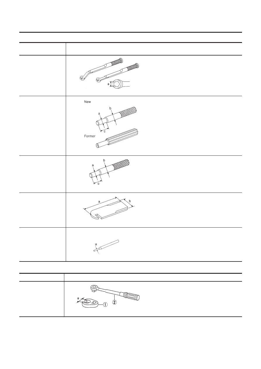
Special Service Tools
NLCL0002
Tool number
Tool name
Description
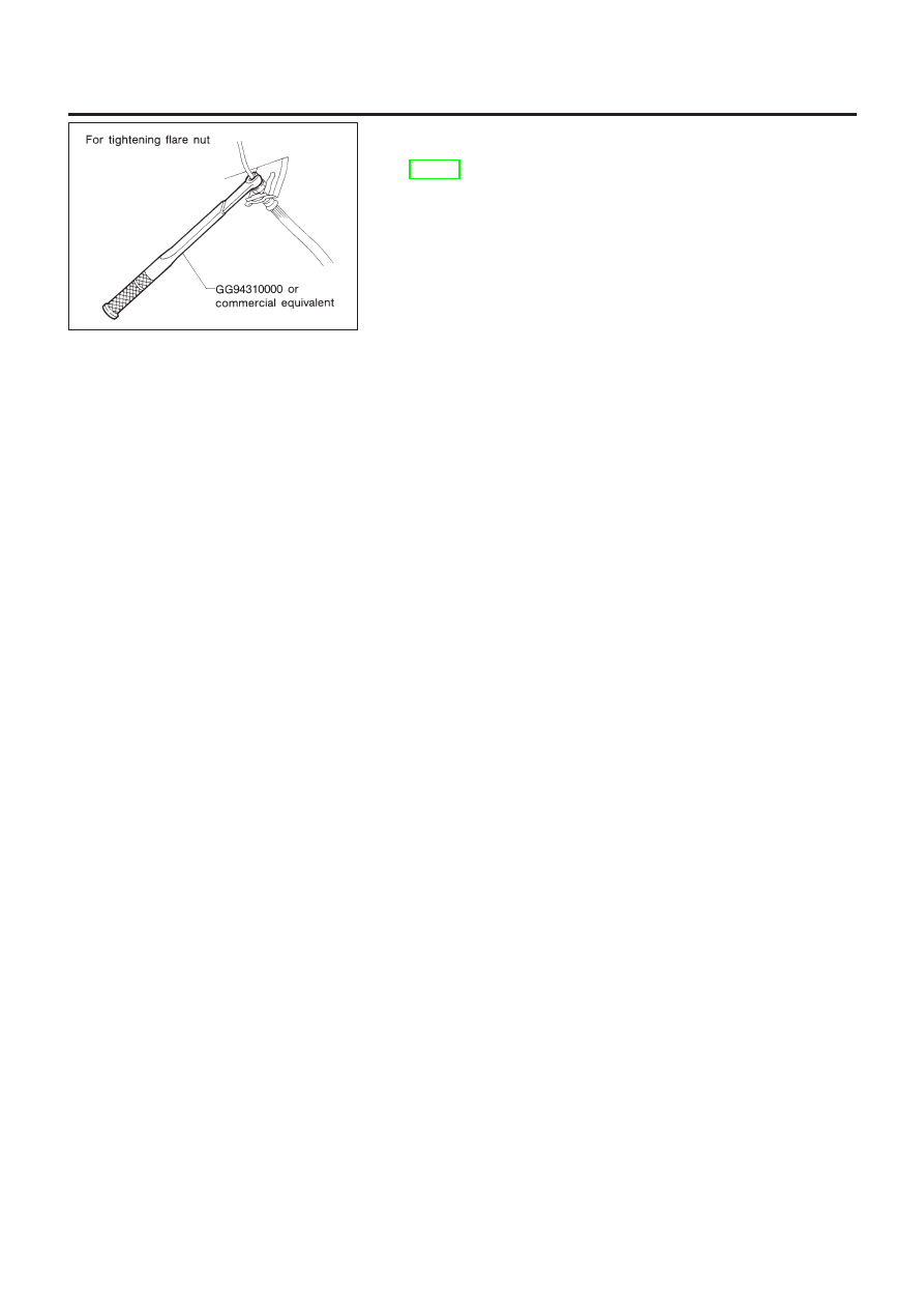
GG94310000
Flare nut torque wrench
NT406
Removing and installing clutch piping
a: 10 mm (0.39 in)
KV30101600 (New)
KV30101000 (Former)
Clutch aligning bar
NT645
Installing clutch cover and clutch disc
(F70A)
a: 15.9 mm (0.626 in) dia.
b: 17.9 mm (0.705 in) dia.
c: 40 mm (1.57 in)
ST20630000
Clutch aligning bar
NT405
Installing clutch cover and clutch disc
(F50A)
a: 15.8 mm (0.622 in) dia.
b: 22.9 mm (0.902 in) dia.
c: 45.0 mm (1.772 in)
ST20050240
Diaphragm spring adjust-
ing wrench
NT404
Adjusting unevenness of diaphragm spring of
clutch cover
a: 150 mm (5.91 in)
b: 25 mm (0.98 in)
KV32101000
Pin punch
NT410
Removing and installing spring pin
a: 4 mm (0.16 in) dia.
Commercial Service Tools
NLCL0003
Tool name
Description
1 Flare nut crowfoot
2 Torque wrench
NT360
Removing and installing clutch piping
a: 10 mm (0.39 in)
PREPARATION
Special Service Tools
CL-3
NLCL0004
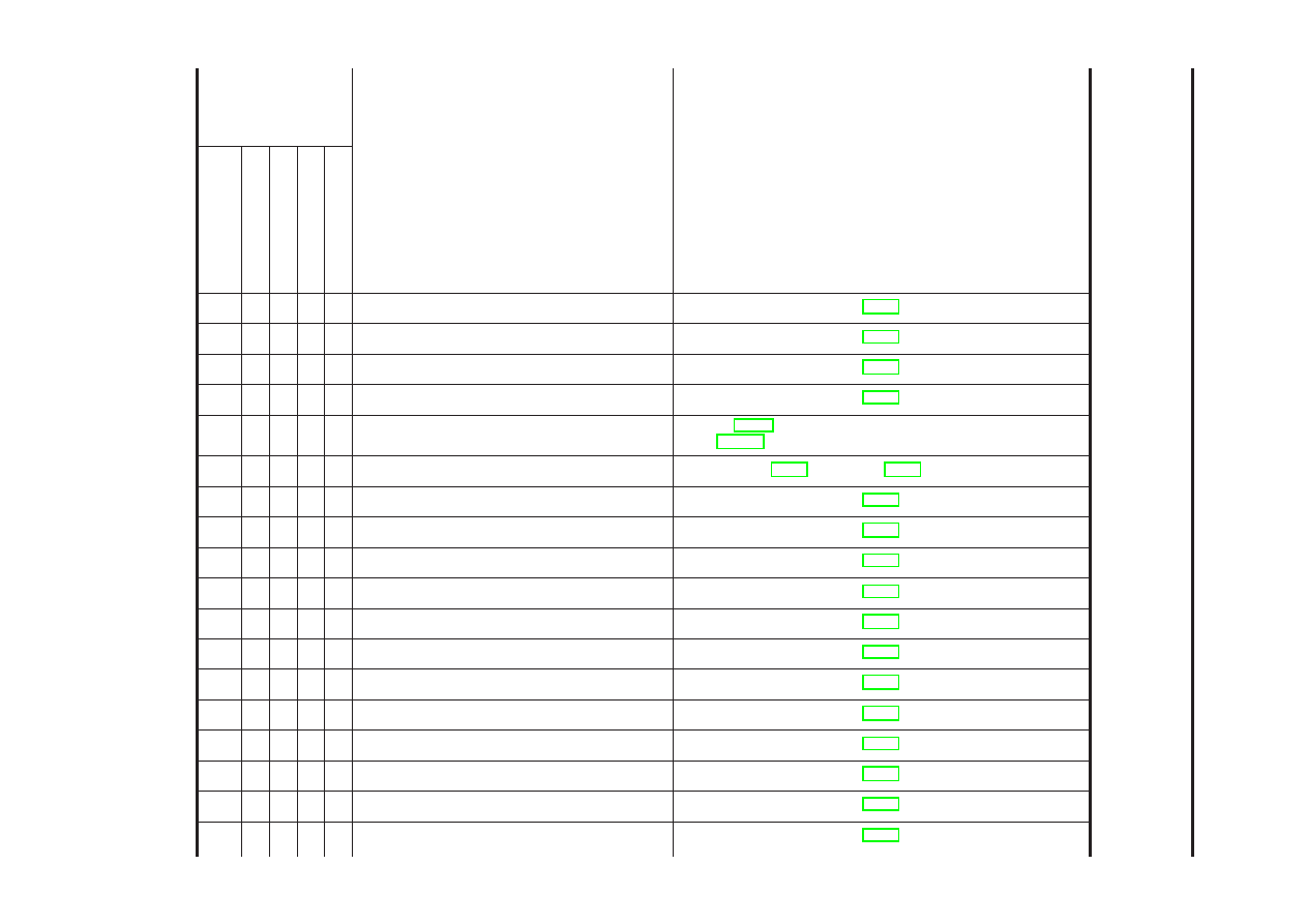
NVH
T
roubleshooting
Chart
NLCL0004S01
Use
the
chart
below
to
help
you
find
the
cause
of
the
symptom.
The
numbers
indicate
the
order
of
the
inspec-
tion.
If
necessary
,
repair
or
replace
these
parts.
CLUTCH
NLCL0004S0101
Reference
page
Refer to EM-49, “Removal and Installation” (QG engine model) and
EM-218, “Removal and Installation” (YD engine model).
CL-17 (RS5F70A), CL-20 (RS5F50A)
SUSPECTED
P
A
R
T
S
(Possible
cause)
CLUTCH PEDAL (Free play out of adjustment)
CLUTCH LINE (Air in line)
MASTER CYLINDER PISTON CUP (Damaged)
OPERATING CYLINDER PISTON CUP (Damaged)
ENGINE MOUNTING (Loose)
RELEASE BEARING (Worn, dirty or damaged)
CLUTCH DISC (Out of true)
CLUTCH DISC (Runout is excessive)
CLUTCH DISC (Lining broken)
CLUTCH DISC (Dirty or burned)
CLUTCH DISC (Oily)
CLUTCH DISC (Worn out)
CLUTCH DISC (Hardened)
CLUTCH DISC (Lack of spline grease)
DIAPHRAGM SPRING (Damaged)
DIAPHRAGM SPRING (Out of tip alignment)
PRESSURE PLATE (Distortion)
FLYWHEEL (Distortion)
Symptom
Clutch
grabs/chatters
1
2
2
2
2
2
Clutch
pedal
spongy
1
2
2
Clutch
noisy
1
Clutch
slips
1
2
2
3
4
5
Clutch
does
not
disen-
gage
1234
55555
5667
NOISE,
V
IBRATION
AND
HARSHNESS
(NVH)
T
ROUBLESHOOTING
NVH
T
roubleshooting
Chart
CL-4
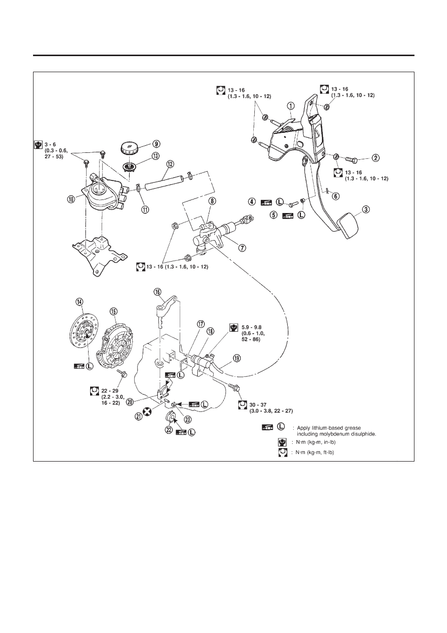
Components — RHD Model with QG Engine —
NLCL0041
NCL046
1.
Clutch pedal bracket
2.
Pedal stopper bolt
3.
Clutch pedal
4.
Clevis pin
5.
Bush
6.
Snap pin
7.
Clutch master cylinder
8.
Nipple
9.
Reservoir cap
10. Reservoir tank
11. Hose clamp
12. Hose
13. Filter
14. Clutch disc
15. Clutch cover
16. Withdrawal lever
17. Spacer
18. Operating cylinder
19. Clutch hose
20. Clutch lever
21. Spring pin
22. Release bearing
23. Release bearing spring
CLUTCH SYSTEM
Components — RHD Model with QG Engine —
CL-5
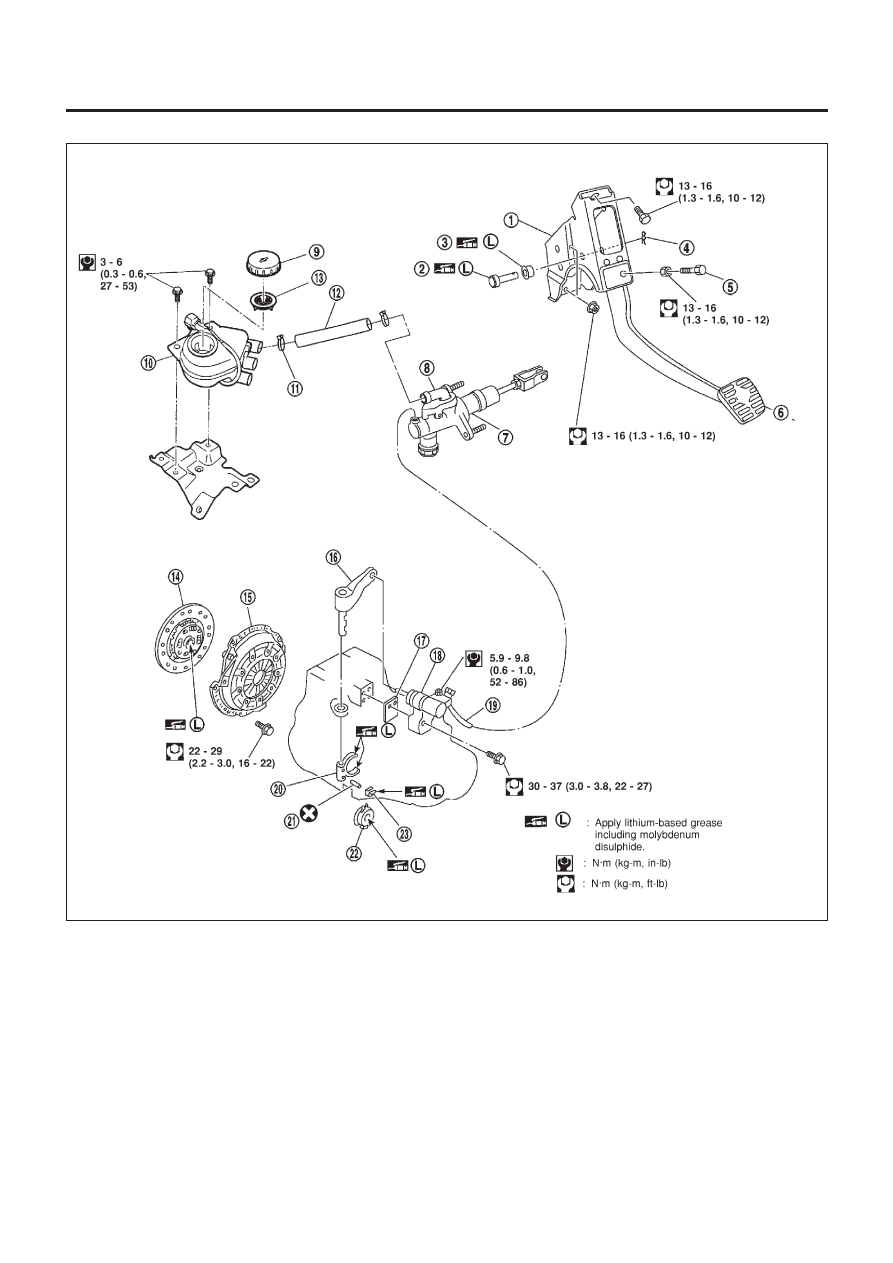
Components — LHD Model with QG Engine —
NLCL0048
NCL047
1.
Clutch pedal bracket
2.
Clevis pin
3.
Bush
4.
Snap pin
5.
Pedal stopper bolt
6.
Clutch pedal
7.
Clutch master cylinder
8.
Nipple
9.
Reservoir cap
10. Reservoir tank
11. Hose clamp
12. Hose
13. Filter
14. Clutch disc
15. Clutch cover
16. Withdrawal lever
17. Spacer
18. Operating cylinder
19. Clutch hose
20. Clutch lever
21. Spring pin
22. Release bearing
23. Release bearing spring
CLUTCH SYSTEM
Components — LHD Model with QG Engine —
CL-6
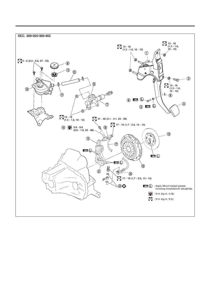
Components — RHD Model with YD Engine —
NLCL0005
NCL048
1.
Clutch pedal bracket
2.
Pedal stopper bolt
3.
Clutch pedal
4.
Clevis pin
5.
Bush
6.
Snap pin
7.
Clutch master cylinder
8.
Nipple
9.
Reservoir cap
10. Reservoir tank
11. Hose clamp
12. Hose
13. Filter
14. Air bleeder screw
15. Withdrawal lever
16. Operating cylinder
17. Clutch hose
18. Clutch disc
19. Clutch cover
20. Clutch hose connector
21. Release bearing
22. Washer
CLUTCH SYSTEM
Components — RHD Model with YD Engine —
CL-7
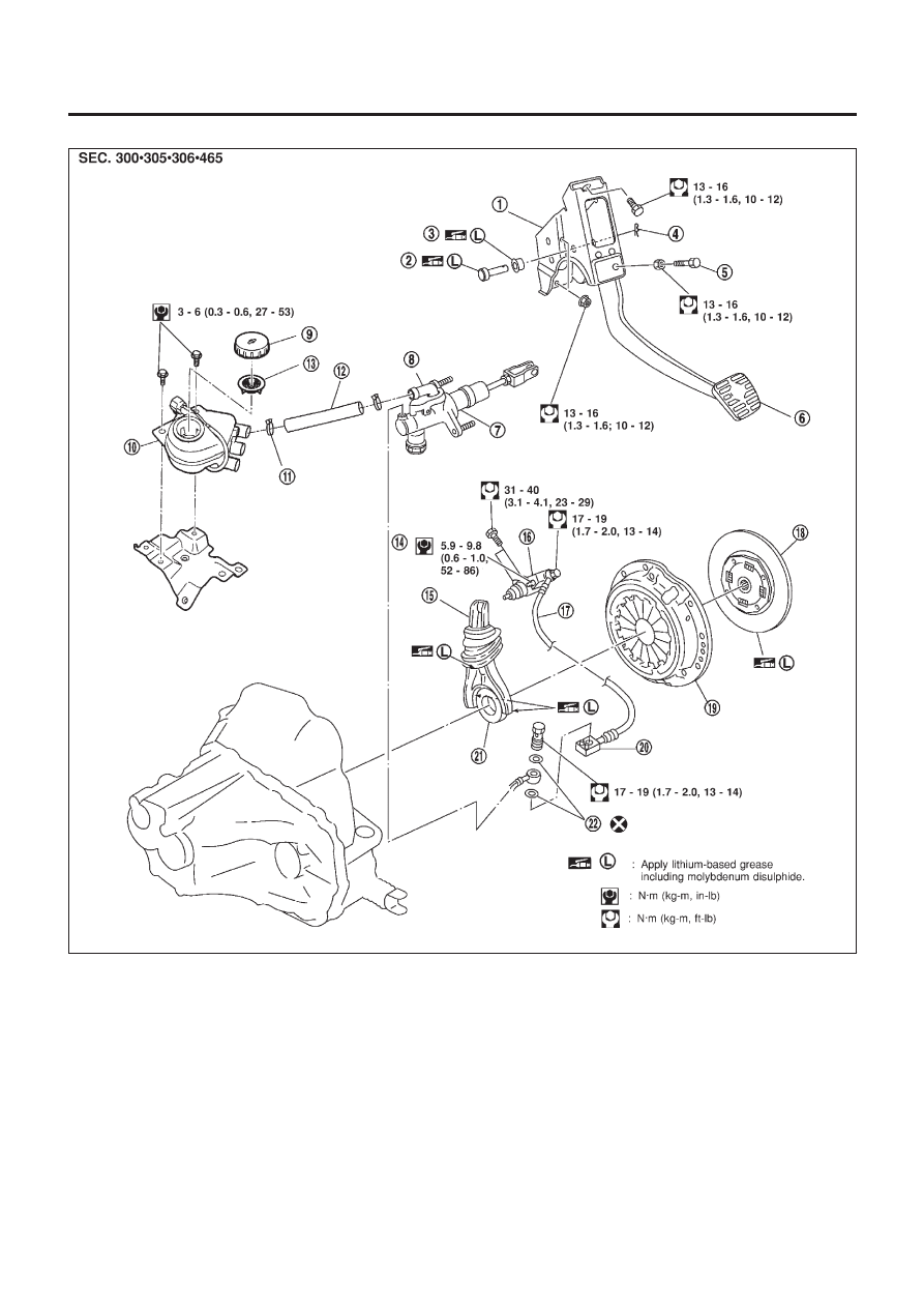
Components — LHD Model with YD Engine —
NLCL0049
NCL049
1.
Clutch pedal bracket
2.
Clevis pin
3.
Bush
4.
Snap pin
5.
Pedal stopper bolt
6.
Clutch pedal
7.
Clutch master cylinder
8.
Nipple
9.
Reservoir cap
10. Reservoir tank
11. Hose clamp
12. Hose
13. Filter
14. Air bleeder screw
15. Withdrawal lever
16. Operating cylinder
17. Clutch hose
18. Clutch disc
19. Clutch cover
20. Clutch hose connector
21. Release bearing
22. Washer
CLUTCH SYSTEM
Components — LHD Model with YD Engine —
CL-8
Inspection and Adjustment
NLCL0006
CLUTCH PEDAL INSPECTION
NLCL0006S04
Pedal Stroke
NLCL0006S0401
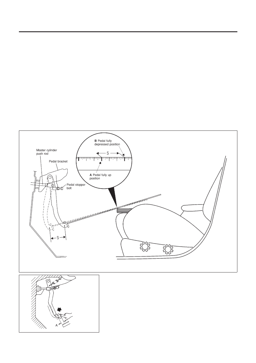
Check clutch pedal stroke by using a 1–meter rule to measure the
total pedal stroke. Place end of rule onto the middle of the clutch
pedal pad. Place a book/clipboard on the driver’s seat to set a ref-
erence point, ensure the book/clipboard does not move during
pedal depression. Mark (A) the pedal fully up position on the rule.
Depress the clutch pedal and mark (B) the rule again next to the
reference point on the book/clipboard. Measure the distance
between the marks (A and B), this is the actual pedal stroke (S).
Check the specified pedal stroke in the table, adjust actual pedal
stroke if necessary (refer to “CLUTCH PEDAL ADJUSTMENT”).
NOTE:
+
Do not use steering wheel as a reference point, angle gives
incorrect reading.
+
Ensure there is no interference between the floor carpet and
clutch pedal when fully depressed.
NCL058
SCL702
Pedal Free Play
NLCL0006S0402
Check pedal free play, if out of specification refer to “CLUTCH
PEDAL ADJUSTMENT”
+
Push on the clutch pedal until resistance is felt, and check the
distance the pedal moves.
CLUTCH SYSTEM
Inspection and Adjustment
CL-9
CLUTCH PEDAL ADJUSTMENT
NLCL0006S01
Pedal Stroke
NLCL0006S0101
1.
Loosen the pedal stopper bolt completely (so there is no con-
tact between pedal and stopper bolt).
2.
Adjust pedal stroke to the specified value with the master cyl-
inder push rod.
3.
Adjust the pedal stopper bolt until it is just in contact with the
pedal, then tighten the lock nut.
4.
Once stroke is set to specification, adjust clutch pedal free
play.
Pedal stroke “S”.
Refer to “SDS”, CL-24.
Pedal Free Play
NLCL0006S0102
1.
Adjust pedal free play to the specified value with the master
cylinder push rod.
2.
Tighten lock nut of the master cylinder push rod.
+
Push on the clutch pedal until resistance is felt, and check the
distance the pedal moves.
Pedal free play “A”.
Refer to “SDS”, CL-24.
SCL838
SCL839
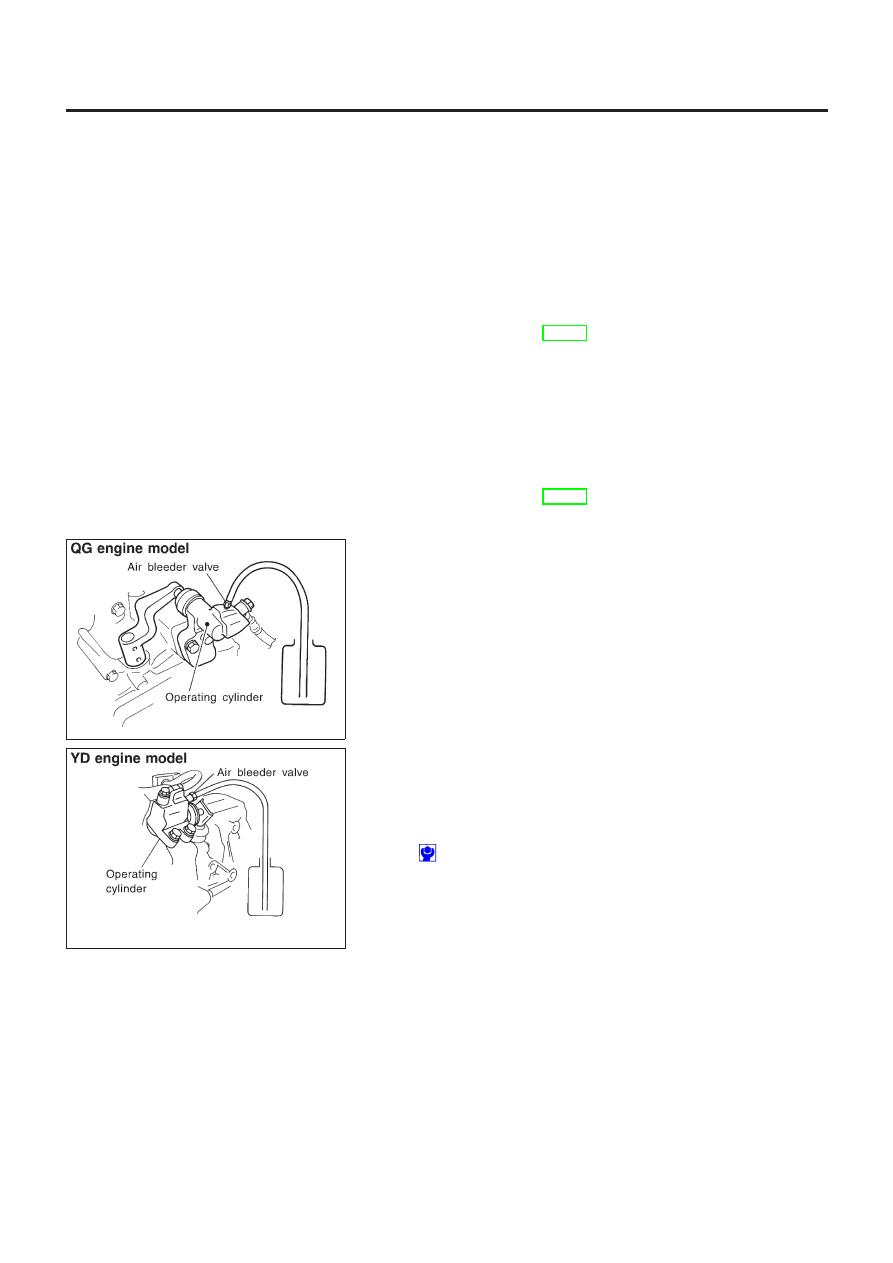
AIR BLEEDING PROCEDURE
NLCL0006S02
1.
Bleed air from clutch operating cylinder according to the fol-
lowing procedure.
+
Carefully monitor fluid level at reservoir during bleeding
operation.
a.
Top up reservoir with recommended brake fluid.
b.
Connect a transparent vinyl tube to air bleeder valve.
c.
Slowly depress the clutch pedal to its full stroke and release it
completely. Repeat this operation several times at 2 to 3 sec-
onds intervals.
d.
Open the air bleeder with the clutch pedal fully depressed.
e.
Close the air bleeder.
f.
Release the clutch pedal and wait at least 5 seconds.
g.
Repeat steps c through f mentioned above, until clear brake
fluid comes out of air bleeder valve.
Air bleeder valve tightening torque:
: 5.9 - 9.8 N·m (0.6 - 1.0 kg-m, 52 - 86 in-lb)
CLUTCH SYSTEM
Inspection and Adjustment (Cont’d)
CL-10
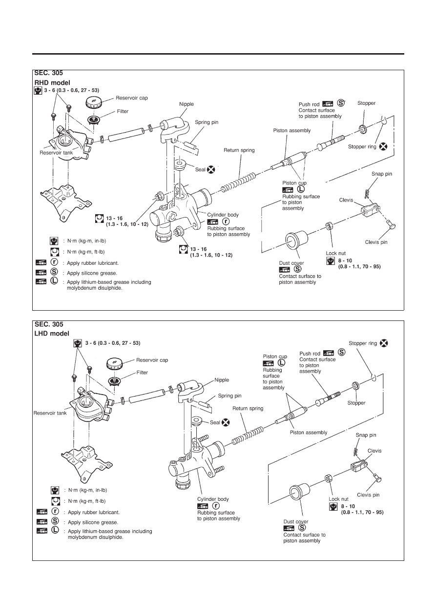
Components
NLCL0007
NCL052
NCL053
CLUTCH MASTER CYLINDER
Components
CL-11
Removal
NLCL0008
1.
Drain brake fluid.
CAUTION:
Be careful not to splash brake fluid on painted areas; it may
cause paint damage. If brake fluid is splashed on painted
areas, wash it away with water immediately.
2.
Remove clutch tube using a flare nut wrench.
3.
Remove snap pin between clutch pedal and push rod, and
remove clevis pin.
4.
Unscrew master cylinder assembly mounting nuts and remove
master cylinder assembly from vehicle.
Installation
NLCL0009
1.
Connect clutch tube to master cylinder assembly, and hand-
tighten flare nut.
2.
Install master cylinder assembly to vehicle, and tighten mount-
ing nuts to the specified torque.
: 13 - 16 N·m (1.3 - 1.6 kg-m, 10 - 12 ft-lb)
3.
Tighten clutch tube flare nut using a flare nut torque wrench.
: 15 - 18 N·m (1.5 - 1.8 kg-m, 11 - 13 ft-lb)
4.
After installing clevis pin, install snap pin to connect clutch
pedal to push rod.
5.
After finishing the operation, bleed air from clutch piping con-
nector and operating cylinder. (Refer to “Air Bleeding
Procedure”, CL-10.)
SCL725
Disassembly
NLCL0010
1.
Loosen push rod lock nut A to remove clevis and lock nut A.
2.
Remove dust cover.
3.
Remove stopper ring and stopper, and remove push rod from
cylinder body. During removal, keep push rod depressed, to
prevent piston inside master cylinder from popping out.
4.
Remove piston assembly from cylinder body.
Inspection
NLCL0011
Check the following items, and replace if necessary.
+
Rubbing surface of cylinder and piston, for uneven wear, rust
or damage
+
Piston with piston cup, for wear or damage
+
Return spring, for wear or damage
+
Dust cover, for cracks, deformation or damage
+
Reservoir, for deformation or damage
CLUTCH MASTER CYLINDER
Removal
CL-12

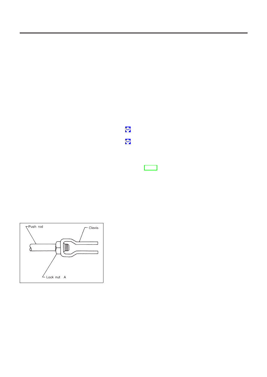
Assembly
NLCL0012
1.
Apply rubber lubricant to the sliding part of piston assembly,
and insert piston assembly.
2.
After installing stopper to push rod, install stopper ring while
keeping piston assembly depressed by hand, so that piston
assembly will not pop out.
CAUTION:
Stopper ring cannot be reused. Always use a new stopper ring
for assembly.
3.
Install dust cover.
4.
Install clevis to push rod, and tighten lock nut A to the speci-
fied torque.
: 8 - 10 N·m (0.8 - 1.1 kg-m, 70 - 95 in-lb)
5.
Install spring pin using a pin punch.
CLUTCH MASTER CYLINDER
Assembly
CL-13
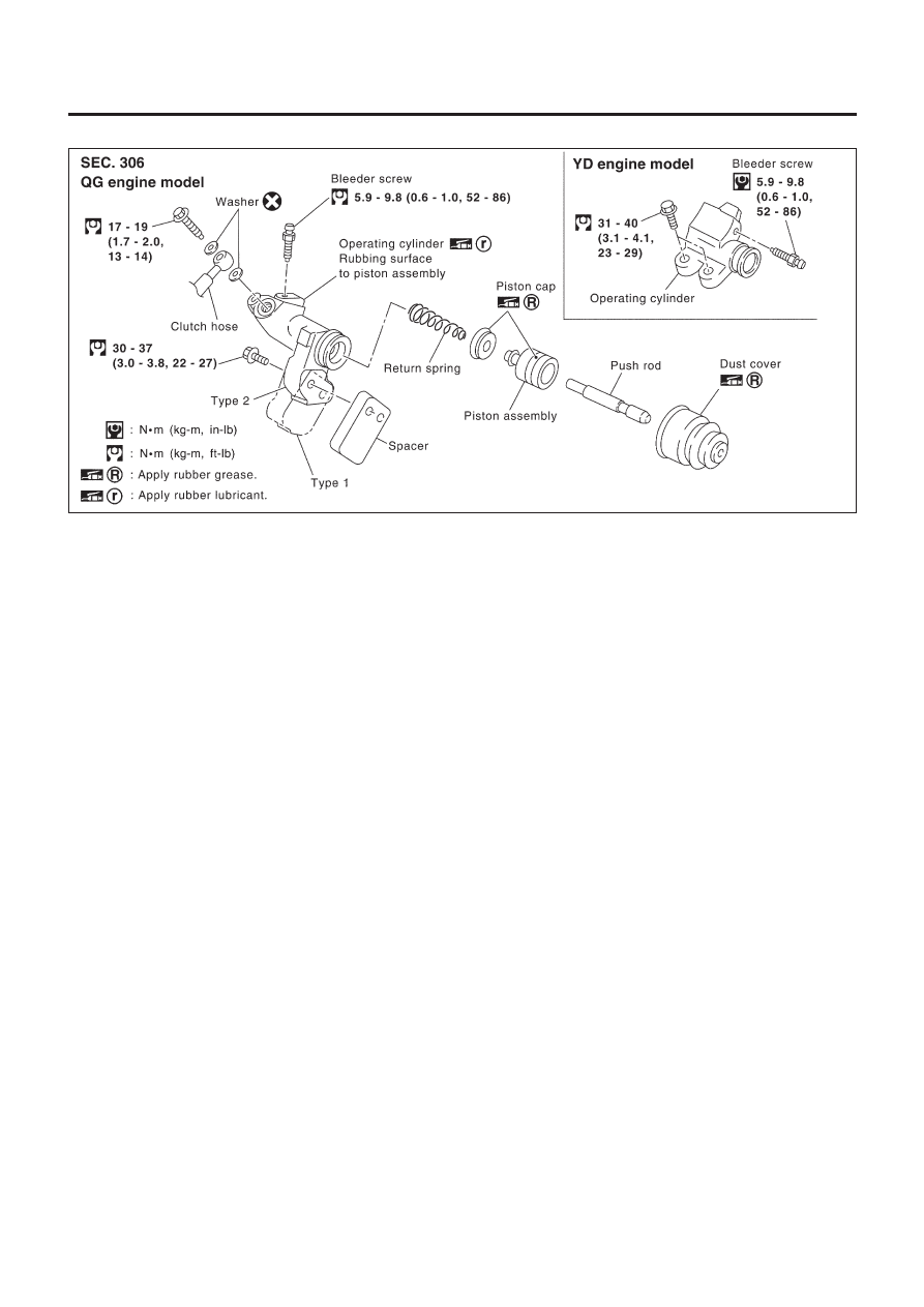
Components
NLCL0019
YCL001
Removal
NLCL0020
1.
Drain brake fluid.
CAUTION:
Be careful not to splash brake fluid on painted areas; it may
cause paint damage. If brake fluid is splashed on painted
areas, wash it away with water immediately.
2.
Remove union bolt and clutch hose from operating cylinder.
3.
Remove operating cylinder mounting bolts, and remove cylin-
der from vehicle.
Disassembly
NLCL0021
Remove dust cover, and remove piston assembly from cylinder
body.
Inspection
NLCL0022
Inspect for following, and replace parts if necessary.
+
Damage, foreign material, wear, rust, and pinholes on the cyl-
inder inner surface, piston, and sliding part of piston cup
+
Weak spring
+
Crack and deformation of dust cover
OPERATING CYLINDER
Components
CL-14

Assembly
NLCL0023
1.
Apply recommended rubber grease to piston cup and piston,
and insert piston assembly.
2.
Install dust cover.
Installation
NLCL0024
Install the components in the reverse order of removal. Adhere to
the operations described below.
CAUTION:
Install the hose without twisting it.
+
The copper washer of the union bolt should not be reused.
Always use a new copper washer for installation.
+
After finishing the operation, bleed air from the clutch
piping connector and operating cylinder. Refer to “Air
Bleeding Procedure”, CL-10.
OPERATING CYLINDER
Assembly
CL-15
SCL729
Removal
NLCL0042
1.
Remove fuel filter mounting bracket.
2.
Remove air cleaner and air duct.
3.
Drain brake fluid.
CAUTION:
Be careful not to splash brake fluid on painted areas; it may
cause paint damage. If brake fluid is splashed on painted
areas, wash it away with water immediately.
4.
Remove flare nut using a flare nut wrench.
5.
Remove clutch hose and clutch tube.
SCL730
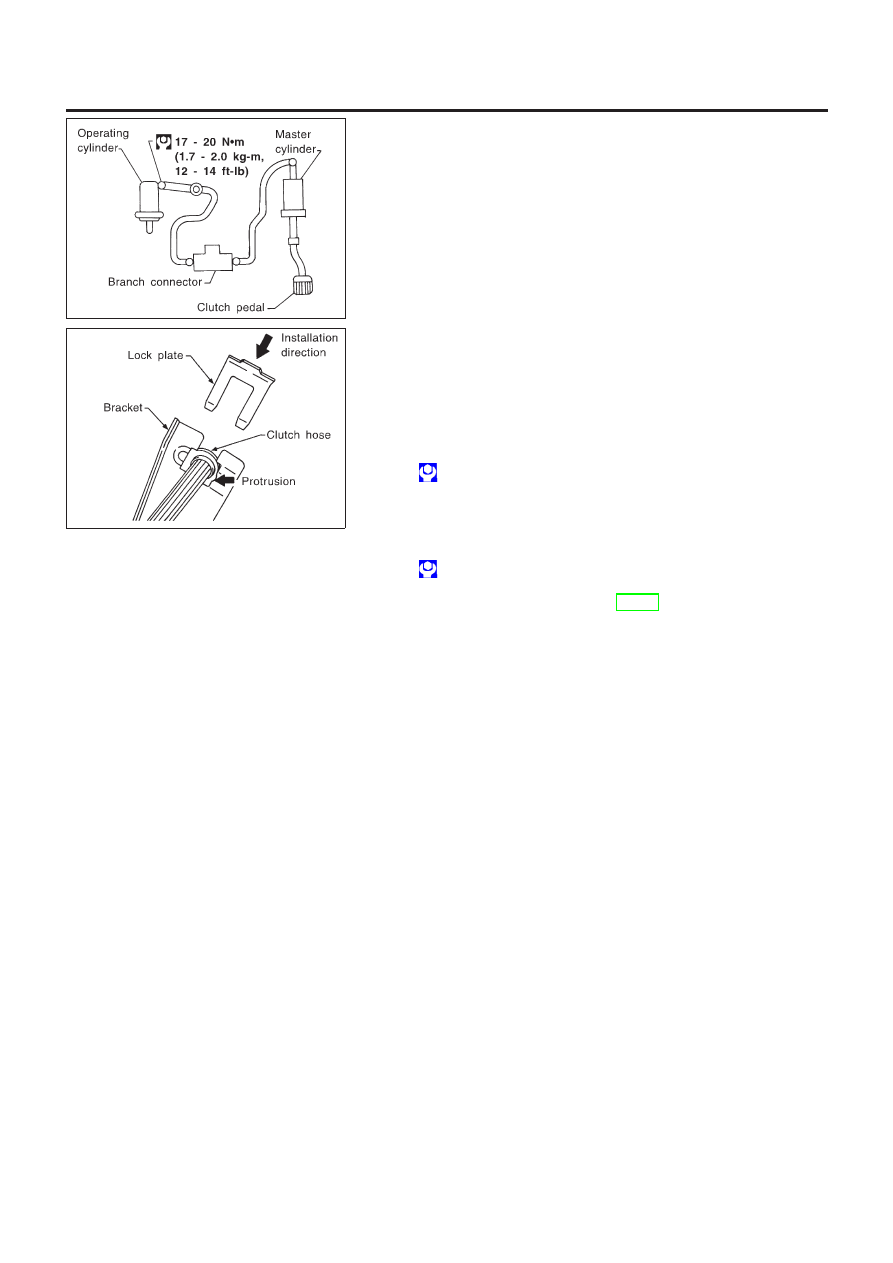
Installation
NLCL0043
1.
When installing clutch hose to bracket, face lock plate in the
correct direction as shown to secure clutch hose.
CAUTION:
Install clutch hose without twisting or bending it.
2.
Tighten flare nut to the specified torque, using a flare nut
wrench.
: 15 - 18 N·m (1.5 - 1.8 kg-m, 11 - 13 ft-lb)
CAUTION:
Be careful not to damage flare nut and clutch tube.
3.
Install clutch hose to operating cylinder, and tighten mounting
bolts to the specified torque.
: 17 - 19 N·m (1.7 - 2.0 kg-m, 13 - 14 ft-lb)
4.
After finishing the operation, bleed air from the clutch piping.
Refer to “Bleeding Procedure”, CL-10.
PIPING
Removal
CL-16
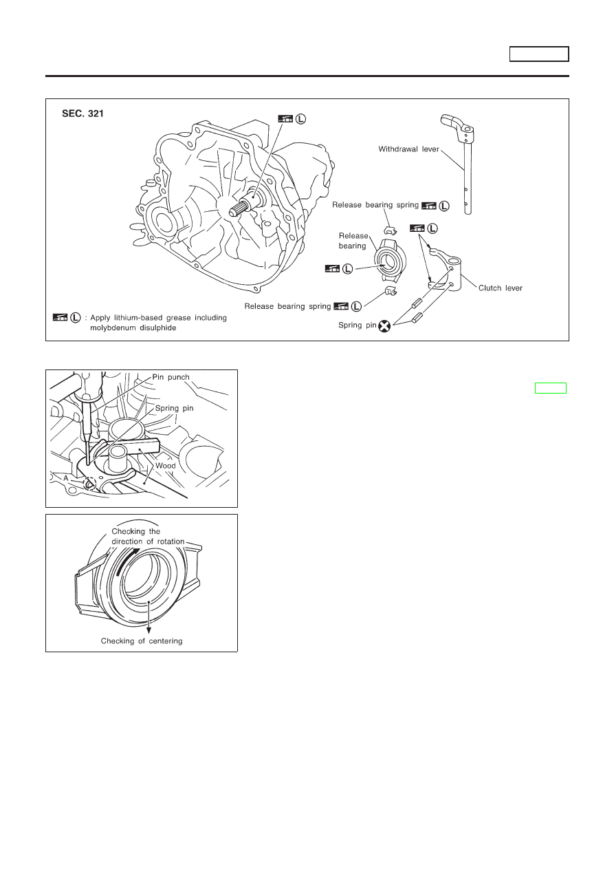
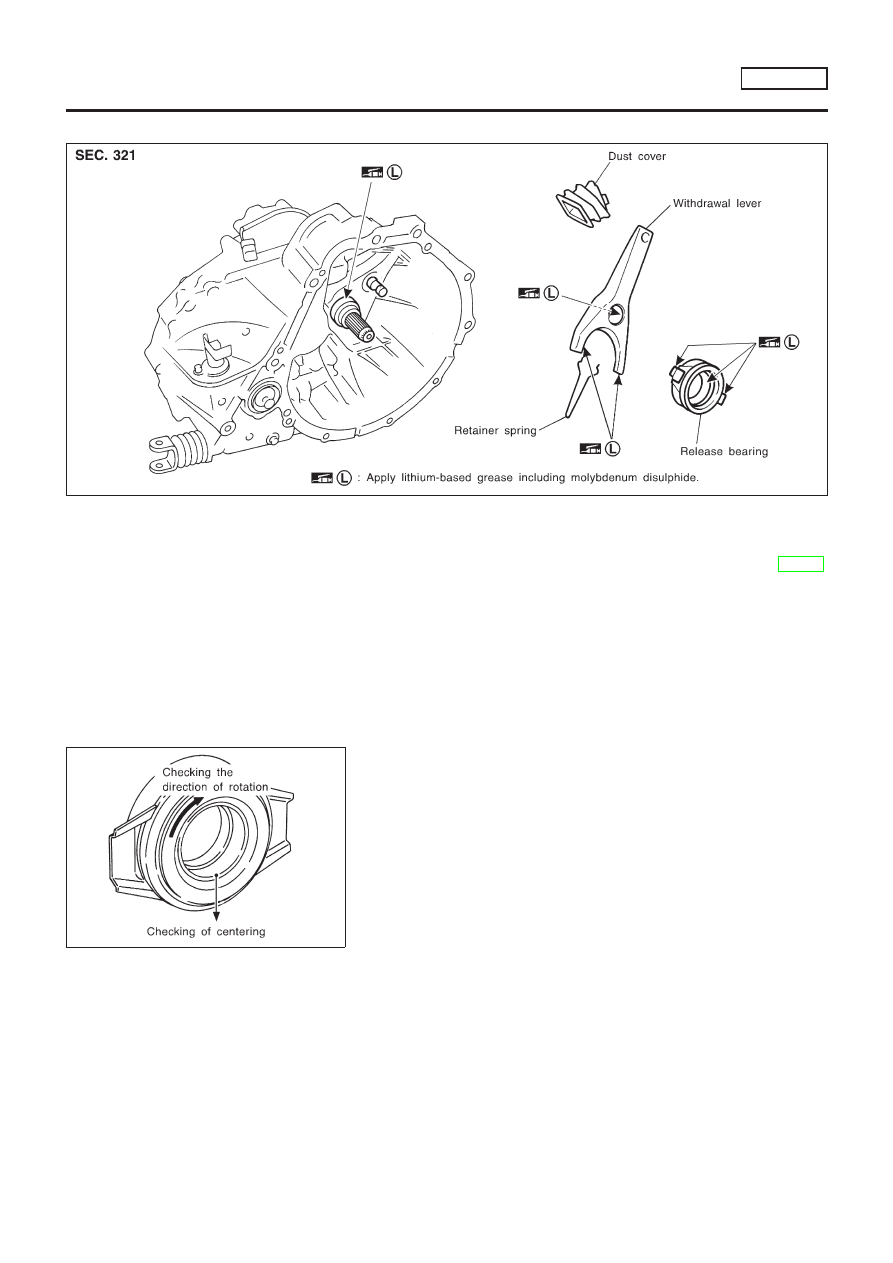
Components
NLCL0044
SCL819
SCL820
Removal
NLCL0045
1.
Remove manual transaxle from vehicle. Refer to MT-18,
“Removal”.
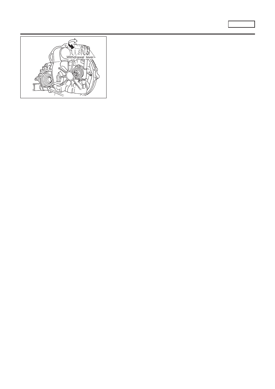
2.
Move withdrawal lever enough to remove release bearing, and
remove release bearing from clutch lever.
3.
Support clutch lever claws with an appropriate wood block,
align retaining pin with A in the figure, and drive out spring pin
using a pin punch.
4.
Pull out withdrawal lever and remove clutch lever.
SCL733
Inspection
NLCL0046
+
Replace the release bearing if it is seized, damaged, faulty in
rotation direction, or has poor aligning function.
+
Replace the withdrawal lever if its contact surface is worn
abnormally.
+
Replace the clutch lever if its contact surface is worn abnor-
mally.
+
Replace the dust seal if it is deformed or cracked.
Installation
NLCL0047
CAUTION:
+
Be sure to apply grease to the clutch components.
Otherwise, abnormal noise, poor clutch disengagement,
or clutch damage may occur. Wipe the excess grease off
completely, because it may cause the clutch components
to slip and shudder.
+
Keep the clutch disc facing, pressure plate, and flywheel
free of oil and grease.
CLUTCH RELEASE MECHANISM
RS5F70A
Components
CL-17
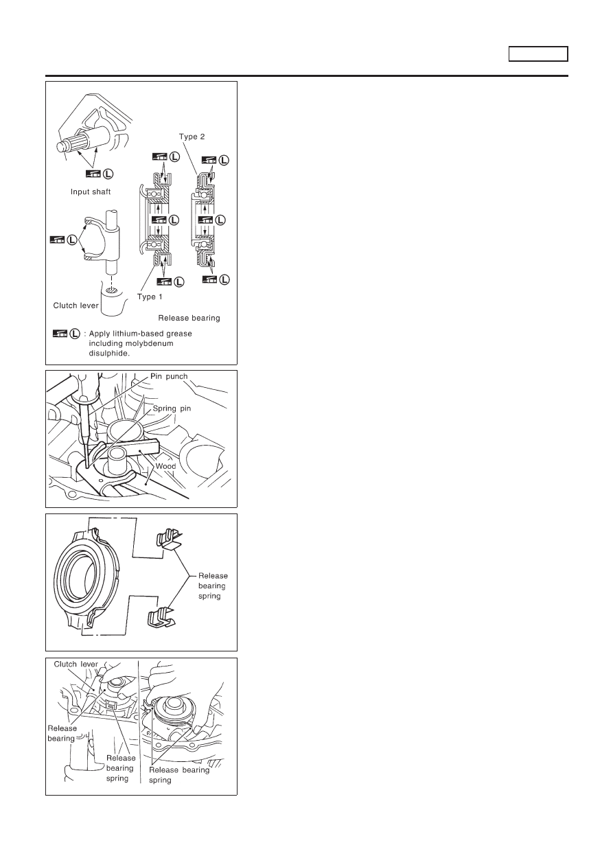
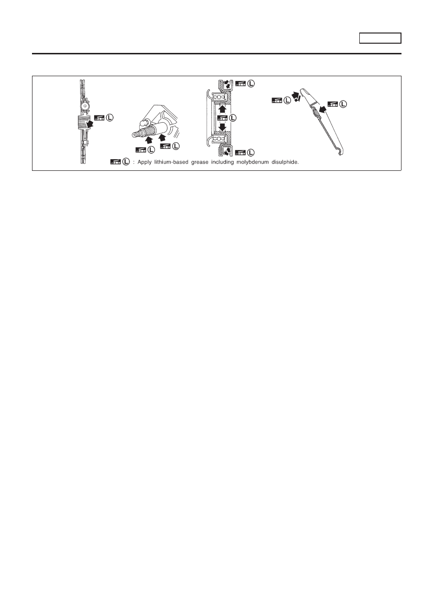
YCL002
+
Clean old grease and abrasive materials off the grease
application area.
+
Apply approximately 1 mm (0.04 in)-thick clutch sleeve
grease evenly on the sliding part of the clutch lever and
the release bearing spring.
+
Apply just enough clutch sleeve grease to fill up the
release bearing inner groove.
+
Apply the clutch grease to the clutch disc and the input
shaft spline. Install the clutch disc to the input shaft,
remove the excess grease around the shaft, and remove
the clutch disc.
+
Lightly and evenly apply the clutch sleeve grease on the
sliding part of the release bearing, install the release
bearing, remove the excess grease around the bearing,
and remove the release bearing.
SCL822
1.
Assemble clutch lever to clutch housing, and insert withdrawal
lever.
2.
Support clutch lever claws with an appropriate wood block, and
install a new spring pin using a pin punch.
CAUTION:
Spring pin cannot be reused.
SCL736
3.
Install release bearing spring to release bearing as shown in
the figure.
SCL823
4.
Operate withdrawal lever manually, press clutch spring from
both sides, and install release bearing to clutch lever securely.
5.
Make sure a click is heard when release bearing spring is
pressed from both sides.
CLUTCH RELEASE MECHANISM
RS5F70A
Installation (Cont’d)
CL-18
SCL738
6.
Make sure each sliding part operates smoothly when with-
drawal lever is moved.
CAUTION:
Remove any excess grease with a shop towel.
CLUTCH RELEASE MECHANISM
RS5F70A
Installation (Cont’d)
CL-19
Components
NLCL0027
SCL842
Removal
NLCL0028
1.
Remove manual transaxle from vehicle. Refer to MT-20,
“Removal”.
2.
Move withdrawal lever enough to remove release bearing, and
remove release bearing from clutch withdrawal lever.
3.
Remove dust cover.
4.
Remove retainer spring from withdrawal lever.
SCL733
Inspection
NLCL0029
+
Replace the release bearing if it is seized, damaged, faulty in
rotation direction, or has poor aligning function.
+
Replace the withdrawal lever if its contact surface is worn
abnormally.
+
Replace the dust cover if it is deformed or cracked.
Installation
NLCL0030
1.
Apply a coat of grease to parts as instructed in the following
cautions and notes before installation.
CAUTION:
+
Be sure to apply grease to the clutch components.
Otherwise, abnormal noise, poor clutch disengagement,
or clutch damage may occur. Wipe the excess grease off
completely, because it may cause the clutch components
to slip and shudder.
+
Keep the clutch disc facing, pressure plate, and flywheel
free of oil and grease.
CLUTCH RELEASE MECHANISM
RS5F50A
Components
CL-20
+
Clean old grease and abrasive materials off the grease
application area.
SCL815
NOTE:
+
Equally apply a coat [approximately 1 mm (0.04 in) thick] of
clutch sleeve grease to withdrawal lever and holder spring
frictional surfaces.
+
Apply a coat of clutch sleeve grease to the grooves on contact
surfaces of the withdrawal lever ball pin and inner surface of
release bearing so that grease application, make sure that
grease is flush with grooves.
+
Equally apply a thin coat of clutch sleeve grease to release
bearing frictional surface. After grease application, install
release bearing. Wipe off excess grease forced out during
bearing installation. Remove release bearing.
2.
Installation is in the reverse order of removal.
CLUTCH RELEASE MECHANISM
RS5F50A
Installation (Cont’d)
CL-21
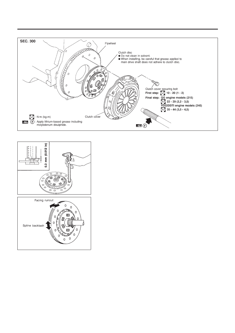
Components
NLCL0031
NCL054
SCL229
Inspection and Adjustment
NLCL0032
CLUTCH DISC
NLCL0032S01
+
Check clutch disc for wear of facing.
Wear limit of facing surface to rivet head:
MODEL 240, MODEL 215
(Part number 30100-
2F205)
0.3 mm (0.012 in)
Wearing thickness of facing:
MODEL 215
(Part number 30100-2F215)
1.3 mm (0.051 in)
SCL221
+
Check clutch disc for backlash of spline and runout of facing.
Maximum spline backlash (at outer edge of disc):
MODEL 215
0.9 mm (0.035 in)
MODEL 240
1.0 mm (0.039 in)
Runout limit:
1.0 mm (0.039 in)
Distance of runout check point (from hub center):
MODEL 215
102.5 mm (4.04 in)
MODEL 240
115 mm (4.53 in)
+
Check clutch disc for burns, discoloration or oil or grease leak-
age. Replace if necessary.
CLUTCH DISC, CLUTCH COVER AND FLYWHEEL
Components
CL-22
SCL466-C
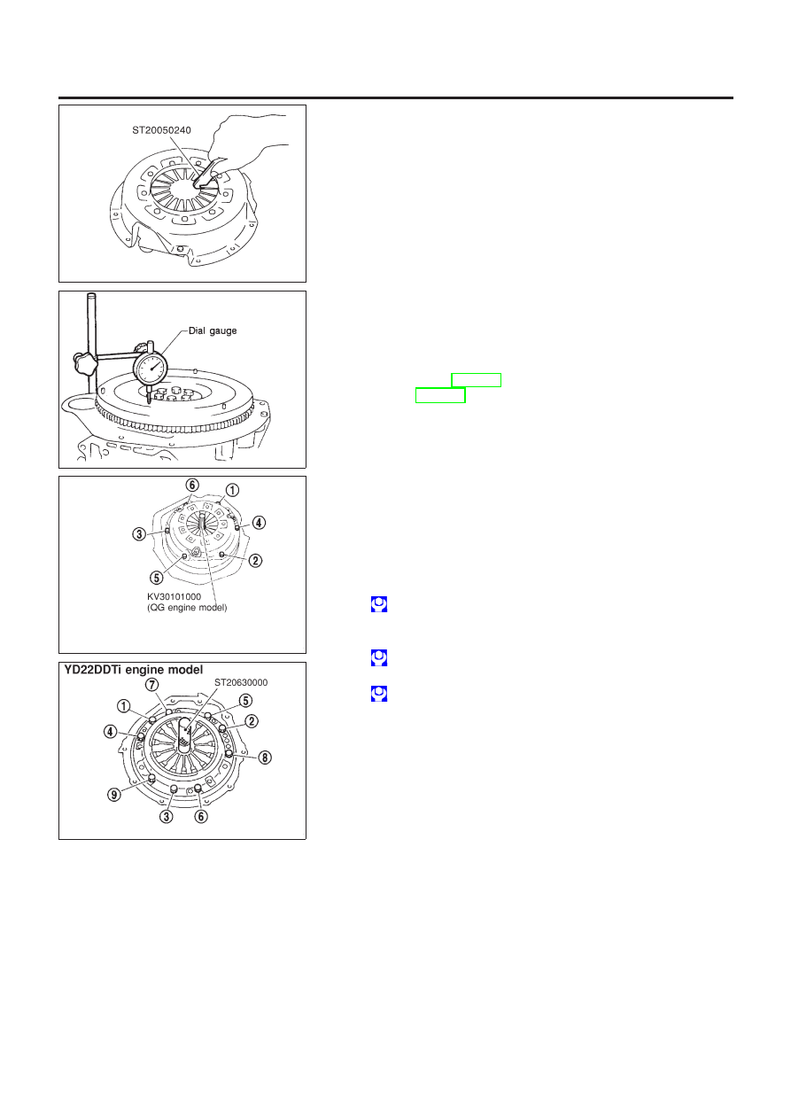
CLUTCH COVER
NLCL0032S02
+
Check clutch cover installed on vehicle for unevenness of dia-
phragm spring toe height.
Uneven limit:
MODEL 240 0.7 mm (0.028 in)
MODEL 215 (Part number 30210-BU000)
0.7 mm (0.028 in)
MODEL 215 (Part number 30210-BU010)
0.8 mm (0.031 in)
+
If out of limit, adjust the height with Tool.
AEM100
FLYWHEEL
NLCL0032S03
+
Check contact surface of flywheel for slight burns or discolora-
tion. Repair flywheel with emery paper.
+
Check flywheel runout.
Maximum allowable runout:
Refer to EM-60, “Flywheel” (QG engine models),
and EM-251, “Flywheel Runout (YD engine models)”.
NCL055
NCL056
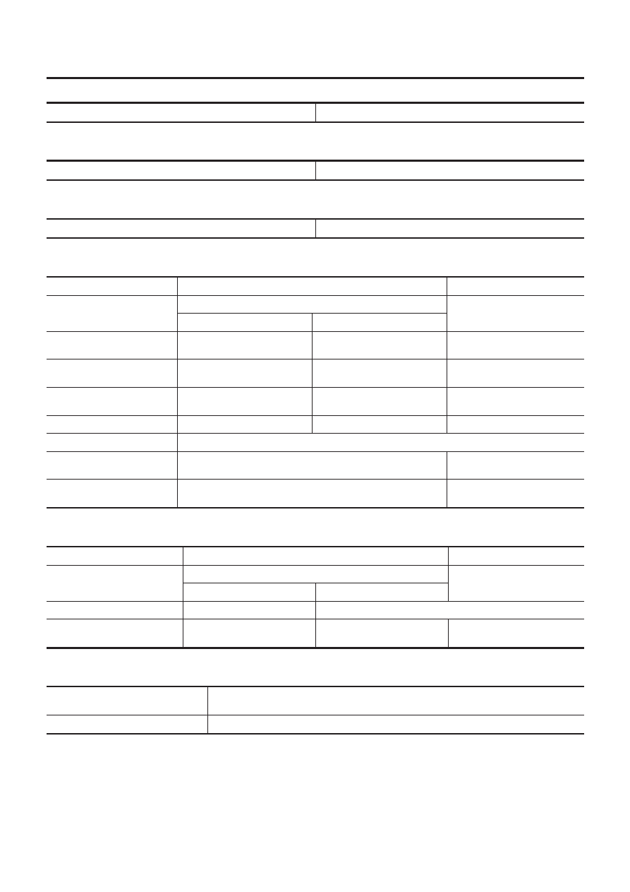
Installation
NLCL0033
+
Insert Tool into clutch disc hub when installing clutch cover and
disc.
+
Be careful not to allow grease to contaminate clutch fac-
ing.
+
Tighten bolts in numerical order.
First step:
: 10 - 20 N·m (1 - 2 kg-m, 7 - 14 ft-lb)
Final step:
QG engine models (215)
: 22 - 29 N·m (2.2 - 3.0 kg-m, 15 - 21 ft-lb)
YD22DDTi engine model (240)
: 35 - 44 N·m (3.5 - 4.5 kg-m, 26 - 32 ft-lb)
CLUTCH DISC, CLUTCH COVER AND FLYWHEEL
Inspection and Adjustment (Cont’d)
CL-23
Clutch Control System
NLCL0034
Type of clutch control
Hydraulic
Clutch Master Cylinder
NLCL0035
Unit: mm (in)
Inner diameter
15.87 (5/8)
Clutch Operating Cylinder
NLCL0036
Unit: mm (in)
Inner diameter
19.05 (3/4)
Clutch Disc
NLCL0038
Unit: mm (in)
Engine
QG18DE
YD22DDTi
Model
215
240
Part number 30100-2F205
Part number 30100-2F215
Facing size (Outer dia.
×
inner
dia.
×
thickness)
215
×
140
×
3.5 (8.46
×
5.51
×
0.138)
216
×
153
×
3.45 (8.50
×
6.02
×
0.1358)
240
×
160
×
3.5 (9.45
×
6.30
×
0.138)
Thickness of disc assembly with
load
7.6 - 8.0 (0.299 - 0.315) with 4,904
N (500 kg, 1,103 lb)
7.3 - 7.9 (0.2874 - 0.3110) with
4,900 N (499.8 kg, 1102 lb)
7.3 - 7.9 (0.2874 - 0.3110) with
4,400 N (448.8 kg, 989.1 lb)
Wear limit of facing surface to
rivet head
0.3 (0.012)
—
0.3 (0.012)
Wearing thickness of facing
—
1.3 (0.051)
—
Runout limit of facing
1.0 (0.039)
Distance of runout check point
(from the hub center)
102.5 (4.04)
115 (4.53)
Maximum backlash of spline (at
outer edge disc)
0.9 (0.035)
1.0 (0.039)
Clutch Cover
NLCL0039
Unit: mm (in)
Engine
QG18DE
YD22DDTi
Model
215
240
Part number 30210-BU000
Part number 30210-BU010
Full-load
4,413 N (450 kg, 992 lb)
4,400 N (448.8 kg, 989.1 lb)
Uneven limit of diaphragm spring
toe height
0.7 (0.028)
0.8 (0.031)
0.7 (0.028)
Clutch Pedal
NLCL0040
Unit: mm (in)
Clutch pedal stroke “S”
140 - 150
(5.512 - 5.709)
Pedal free play “A”
1 - 3 (0.04 - 0.12)
SERVICE DATA AND SPECIFICATIONS (SDS)
Clutch Control System
CL-24
Document Outline
- Quick Reference Index
- Table of Contents
- PRECAUTIONS
- PREPARATION
- NOISE, VIBRATION AND HARSHNESS (NVH) TROUBLESHOOTING
- CLUTCH SYSTEM
- CLUTCH MASTER CYLINDER
- OPERATING CYLINDER
- PIPING
- RS5F70A - CLUTCH RELEASE MECHANISM
- RS5F50A - CLUTCH RELEASE MECHANISM
- CLUTCH DISC, CLUTCH COVER AND FLYWHEEL
- SERVICE DATA AND SPECIFICATIONS (SDS)
Wyszukiwarka
Podobne podstrony:
LAB EL EN PC schematy
schemat sprzęgło hydrauliczne
en schemaAdapter
Citroen C5 Siłownik sprzęgła schemat
Citroen C5 Siłownik sprzęgła schemat
Thermo Top Z C opis i schematy [EN]
06 pamięć proceduralna schematy, skrypty, ramyid 6150 ppt
7 aglebra schematow bloczkowych
wZ 2 Budowa wiedzy społecznej teoria schematów
3 ogolny schemat replikacji i onkogeza DNA wirusowa
Schematy animacji
wykład 5 schematy, przywileje, role
schemat mechanika
Przekladnie i sprzegla
schemacik prezentacji
5 Algorytmy i schematy blokowe
Sprzęgła
więcej podobnych podstron